

Page 1

Kramer Electronics, Ltd.
Preliminary
USER MANUAL
Model:
TP-305A
UXGA – Audio – RS-232 Line Receiver/DA
Page 2

Contents
Contents
1 Introduction 1
2 Getting Started 1
2.1 Quick Start 2
3 Overview 3
3.1 About the Power Connect Feature 4
3.2 Shielded Twisted Pair (STP)/Unshielded Twisted Pair (UTP) 4
4 Your TP-305A UXGA - Audio - RS-232 Line Receiver/DA 5
4.1 The TP-305A UXGA - Audio - RS-232 Line Receiver/DA Underside 6
5 Connecting the TP-305A UXGA-Audio-RS-232 Line Receiver/DA 6
5.1 Connecting a Single TP-305A 6
5.2 Connecting Several TP-305A Units 8
5.3 Wiring the CAT 5 LINE IN / LINE OUT RJ-45 Connectors 10
5.4 Wiring the RS-232 Connector 10
6 Technical Specifications 11
Figures
Figure 1: TP-305A UXGA - Audio - RS-232 Line Receiver/DA 5
Figure 2: TP-305A Underside 6
Figure 3: Connecting the TP-305A UXGA - Audio - RS-232 Line Receiver/DA 8
Figure 4: Distributing the Signal to 17 Receivers 9
Figure 5: CAT 5 PINOUT 10
Figure 6: RS-232 PINOUT Connection 10
Tables
Table 1: TP-305A UXGA - Audio - RS-232 Line Receiver/DA Features 5
Table 2: Features of the TP-305A Underside 6
Table 3: CAT 5 PINOUT 10
Table 4: RS-232 PINOUT Connection 10
Table 5: Technical Specifications of the TP-305A 11
i
Page 3

Introduction
1 Introduction
Welcome to Kramer Electronics! Since 1981, Kramer Electronics has been
providing a world of unique, creative, and affordable solution s to the vast
range of problems that confront the video, audio, presentation, and
broadcasting professional on a daily basis. In recent years, we have
redesigned and upgraded most of our line, making the best even better! Our
1,000-plus different models now appear in 11 groups
1
that are clearly
defined by function.
Thank you for purchasing the Kramer TP-305A UXGA - Audio - RS-232
Line Receiver/DA, which is ideal for:
• Presentation and multimedia applications
• Long range graphics distribution for schools, hospitals, security, and
stores
The package includes the following items:
• TP-305A UXGA - Audio - RS-232 Line Receiver/DA
• Power supply (12V DC)
• This user manual
2
2 Getting Started
We recommend that you:
• Unpack the equipment carefully and save the original box and
packaging materials for possible future shipment
• Review the contents of this user manual
• Use Kramer high performance high-resolution cables
3
1 GROUP 1: Distribution Amplifiers; GROUP 2: Switchers and Matrix Switchers; GROUP 3: Control Systems;
GROUP 4: Format/Standards Converters; GROUP 5: Range Extenders and Repeaters; GROUP 6: Specialt y AV Products;
GROUP 7: Scan Converters and Scalers; GROUP 8: Cables and Connectors; GROUP 9: Room Connectivity;
GROUP 10: Accessories and Rack Adapters; GROUP 11: Sierra Products
2 Download up-to-date Kramer user manuals from our Web site at http://www.kramerelectronics.com
3 The complete list of Kramer cables is on our Web site at http://www.kramerelectronics.com
1
Page 4
Getting Started
2.1 Quick Start
This quick start chart summarizes the basic setup and operation steps of the
TP-305A.
Step 1: Connect the input and the outputs - see section 5
TP-305A
2
LIN
INE
1
STP Cable
Range up to
300ft (100m)
XGAIN
Audio
Computer Graphics /
RS-232 Control
LOUT
INE
Audio /
UXGAOUT
TP-123
TP-123
12VDC
RS-232
Plasma
Display
XGA/ Audio /Data LineTransmitter
XGAOUT
LIN
INE
VGA
RS-232
GND
RXD
RS-232RS-232
AIN
UDIO
VGA
STP Cable
Range up to
300ft (100m)
TP-124
GND
TXD
A
NALOG
RS-232
AOUT
Audio
Audio
3
12345
LO
INE UTPUTS
TP-124
S/PDIF
UDIO
12VDC
Plasma
Display
1
AOUT
UDIO
A
NALOG
S/PDIF
RS-232
12V DC
GTx
TP-124
VGA
XGAOUT
Plasma
Display
LIN
INE
RS-232
TP-124
GND
TXD
A
NALOG
RS-232
S/PDIF
AOUT
UDIO
STP Cable
Range up to
300ft (100m)
XGA/ Audio /Data LineReceiver
VGA
Audio
RS-232
XGA/ Audio /Data LineReceiver
12VDC
Audio
AV-Receiver
Connect the UXGA video and audio outputs, and the RS-232 port (if required)
Connect the UXGA video and audio outputs, and the RS-232 port (if required)
1
to the TP-123 transmitter
to the TP-123 transmitter
Connect the TP-123 transmitter to the TP-305A via CAT 5
Connect the TP-123 transmitter to the TP-305A via CAT 5
2
Connect the TP-305A to up to five TP-124 receivers via CAT 5
Connect the TP-305A to up to five TP-124 receivers via CAT 5
3
Step 2: Set the underside switches - see section 5Step 2: Set the underside switches - see section 5
Set the Hs and Vs
Set the Hs and Vs
polarity switches
polarity switches
Step 3: Connect the power
2
KRAMER: SIMPLE CREATIVE TECHNOLOGY
Page 5
3 Overview
Overview
The TP-305A UXGA - Audio - RS-232 Line Receiver/DA receives a CAT 5
signal from a transmitter
1
and distributes it to up to five other receivers (via
CAT 5 cables). The TP-305A also decodes the CAT 5 signal and distributes
it to a UXGA output, an analog audio output, a digital audio output and an
RS-232 output.
The TP-305A serves as a power center that can distribute power to both the
transmitter and the connected receivers (see section 3.1
).
In particular, the TP-305A features:
• Resolution of up to UXGA
• UXGA output on a 15-pin HD computer graphi cs video connector
• Digital audio output (S/PDIF) on an RCA connector and an analog
audio output on a 3.5mm mini jack
• A transmission range of up to 300ft (up to 100 meters) over STP
cabling
• Changeable polarity of the encoded H and V Sync for video (UXGA)
• EQ. and LEVEL controls for the video (UXGA) output
To achieve the best performance:
• Use only good quality connection cables
2
to avoid interference,
deterioration in signal quality due to poor matching, and elevated noise
levels (often associated with low quality cables).
• Avoid interference from neighboring electrical appliances that may
adversely influence signal quality and position your Kramer TP-305A
away from moisture, excessive sunlight and dust
1 For example, the Kramer TP-121, TP-123 or TP-45
2 Available from Kramer Electronics on our Web site at http://www.kramerelectronics.com
3
Page 6

Overview
3.1 About the Power Connect Feature
The Power Connect feature applies as long as the cable can carry power.
This feature is available when using STP cable and the distance does not
exceed 50m on standard CAT 5 cable. For longer distances, heavy gauge
cable should be used
1
. For units which are connected via RJ-45 connectors,
make sure that the shield of the STP cable is connected to the metal casing
of the connectors on both ends of the cable. For units which are connected
via terminal block connectors, the shield of the STP cable must be
connected to a ground terminal on the units at both ends (use the ground
terminal of the power supply connection if necessary).
For a CAT 5 cable exceeding a distance of 50m, separate power suppli es
should be connected to the transmitter and to the receiver simultaneously.
3.2 Shielded Twisted Pair (STP)/Unshielded Twisted Pair (UTP)
recommend that you use Shielded Twisted Pair (STP) cable. There are
We
different levels of STP cable available, and we advise you to use the best
quality STP cable that you can afford. Our non-skew-free cable, Kramer
BC-STP is intended for analog signals where skewing is not an issue. For
cases where there is skewing, our UTP skew-free cable, Kramer BC-XTP,
may be used. Bear in mind, though, that we advise using STP cables where
possible, since the compliance to electromagnetic interference was tested
using those cables.
Although Unshielded Twisted Pair (UTP) cable might be preferred for long
range applications, the UTP cable should be installed far away from electric
cables, motors and so on, which are prone to cre ate electrical interference.
However, since the use of UTP cable might cause inconform ity to
electromagnetic standards, Kramer does not commit to meeting the standard
with UTP cable.
1 CAT 5 cable is still suitable for the video/audio transmission, but not for feeding the power at these distances
4
KRAMER: SIMPLE CREATIVE TECHNOLOGY
Page 7

Your TP-305A UXGA - Audio - RS-232 Line Receiver/DA
4 Your TP-305A UXGA - Audio - RS-232 Line Receiver/DA
Figure 1 and Table 1 define the TP-305A:
Figure 1: TP-305A UXGA - Audio - RS-232 Line Receiver/DA
Table 1: TP-305A
# Feature Function
1 POWER Switch Illuminated switch for turning the unit ON or OFF
2 LINK LED Lights when receiving a valid input signal
3 EQ.1 Trimmer Adjusts2 the cable compensation (equalization) level for the
4 LEVEL Trimmer Adjusts2 the output signal level for the UXGA output
5 LINE IN RJ-45 Connector Connect to the LINE OUT connector of a t r ansm itter3
6 UXGA OUT 15-pin HD Connector Connect to the video acceptor
7 LINE OUTPUT RJ-45 Connectors Connect to4 the LINE IN RJ-45 connector o n a r e c e i v e r5 (from 1
8
AUDIO OUT
9 S/PDIF RCA
10 RS-232 G, Tx Terminal Block Connect the connector (G and Tx) to control a device (see
11 Power Connector with Fuse AC connector enabling power supply to the unit
1 Degradation and VGA/XGA signal loss can result from using long cables (due to the effects of stray capacitance, for
example), sometimes leading to a loss of sharpness in high-resolution signals
2 Use a screwdriver to carefully rotate the trimmer, adjusting the appropriate level
3 The PINOUT is defined in Table 3
4 Using UTP or STP cable with RJ-45 connectors at both ends (the PINOUT is defined in Table 3
5 For example, the Kramer TP-124 or TP-46
UXGA - Audio - RS-232 Line Receiver/DA Features
UXGA output
to 5)
ANALOG 3.5mm
Mini Jack
Connector
and Figure 5
Connect to the stereo analog audio acceptor 1
Connect to the digital audio acceptor 1
section 5.3
)
and Figure 5)
5
Page 8

Connecting the TP-305A UXGA-Audio-RS-232 Line Receiver/DA
4.1 The TP-305A UXGA - Audio - RS-232 Line Receiver/DA Underside
Figure 2
and Table 2 define the underside of the TP-305A
Figure 2: TP-305A Underside
Table 2: Features of the TP-305A Underside
Feature Function
VS Switch1 Slide the switch down, to set the V SYNC to its input polarity (NORMAL)
HS Switch1 Slide the switch down, to set the HS to its input polarity (NORMAL)
Slide the switch up, to set the VS to negative polarity (INVERT)
Slide the switch up, to set the HS to negative polarity (INVERT)
5 Connecting the TP-305A UXGA-Audio-RS-232 Line
Receiver/DA
You can use the TP-305A with a UXGA - Audio - RS-232 Line Receiver/DA
such as the Kramer TP-123
receivers, and up to five TP-305A units can be connected to increase the
number of outputs to 25.
5.1 Connecting a Single TP-305A
nect a TP-123/TP-305A UXGA – Audio - RS-232/Line
To con
Receiver/DA system
following
4
:
1. On the TP-305A, connect the:
UXGA OUT 15-pin HD computer graphics video connector to the
UXGA acceptor (for example, a plasma display), and the AUDIO
OUT ANALOG 3.5mm mini jack connector to the analog audio
connector on the acceptor. If required, connect the RS-232 G and
TX terminal block connector to the RS-232 port on the acceptor
LINE OUTPUT RJ-45 connector on the TP-123 to the LINE IN
1 By default, both switches are set to NORM.
2 Refer to the separate user manual, which can be downloaded at: http://www.kramerelectronics.com
3 Using up to 300ft (100m) of UTP cabling
4 Switch OFF the power on each device before connecting it to your TP-305A. After connecti ng your TP-305A, switch on i ts
power and then switch on the power on each device
2
. You can connect a single TP-305A to up to five
3
as illustrated in the example in Figure 3, do the
6
KRAMER: SIMPLE CREATIVE TECHNOLOGY
Page 9

Connecting the TP-305A UXGA-Audio-RS-232 Line Receiver/DA
RJ-45 connector on the TP-305A, via STP cabling (with a range of
up to 300ft (up to100m)), see section 3.2
2. On the TP-123, connect:
A UXGA source (for example, the graphics card of a laptop) to the
XGA IN 15-pin HD computer graphics video connector and an
audio source to the Audio IN 3.5mm mini jack, for example, using
a Kramer C-GMA/GMA cable (VGA HD15M +Audio jack to
VGA HD15M +Audio jack)
1
An RS-232 cable with a 9-pin D-sub connector at one end to the
laptop, and a 2-PIN terminal block connector at the other end to
the TP-123 RS-232 port
2
3. Connect the LINE OUTPUT CAT 5 connect ors as follows
The LINE OUTPUT 1 RJ-45 connector on the TP-305A to the
LINE IN RJ-45 connector on a TP-124
(with a range of up to 300ft (up to 100m))
3
unit via STP cabling4
5
The LINE OUTPUT 5 RJ-45 connector on the TP-305A to the
LINE IN RJ-45 connector on another TP-124
4
cabling
(with a range of up to 300ft (up to 100m))
:
3
unit, via STP
4. Connect the 12V DC power adapter to the power socket and connect the
adapter to the mains electricity.
6
5. If necessary, set the HS and VS switches
on the underside.
1 Not supplied. The full list of Kramer cables is on our Web site at http://www.kramerelectronics.com. Alternativel y, you can
connect an XGA source to the XGA IN 15-pin HD connector, and a separate audio source to the AUDIO IN 3.5mm mini jack
2 You do not have to connect all the outputs
3 Refer to the separate user manual, which can be downloaded at http://www.kramerelectronics.com
4 For details of how to wire a CAT 5 LINE IN/LINE OUT RJ-45 connector, see section 5.3
5 The TP-46 is connected to an additional TP-46 unit for transmitting the signal further
6 By default, both switches are set down (for normal V SYNC and H SYNC polarity)
7
Page 10

Connecting the TP-305A UXGA-Audio-RS-232 Line Receiver/DA
TP-305A
LIN
INE
UXGAOUT
12345
LO
INE UTPUTS
AOUT
UDIO
A
NALOG
S/PDIF
STP Cable
Range up to
300ft (100m)
XGAIN
Audio
Computer Graphics /
Audio /
RS-232 Control
LOUT
INE
TP-123
TP-123
XGA/ Audio / Data LineTransmitter
VGA
STP Cable
Range up to
300ft (100m)
TP-124
TP-124
XGAOUT
LIN
GND
INE
TXD
A
NALOG
RS-232
S/PDIF
AOUT
UDIO
12VDC
RS-232
Audio
Audio
Plasma
Display
GND
RXD
RS-232RS-232
AIN
UDIO
12VDC
VGA
RS-232
Plasma
Display
RS-232
12V DC
GTx
LIN
INE
RS-232
Plasma
Display
TP-124
GND
TXD
A
NALOG
RS-232
S/PDIF
AOUT
UDIO
STP Cable
Range up to
300ft (100m)
XGAOUT
XGA/ Audio / Data LineReceiver
VGA
Audio
VGA
RS-232
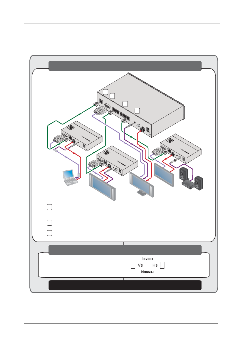
Figure 3: Connecting the TP-305A UXGA - Audio - RS-232 Line Receiver/DA
TP-124
XGA/ Audio / Data LineReceiver
12VDC
Audio
AV-Receiver
5.2 Connecting Several TP-305A Units
You can connect up to five additional TP-305A units via the LINE
OUTPUT RJ-45 connectors on the first unit. The number of TP-305A units
that can be connected depends upon the quality of the input signal that you
require and the distance between the machines.
In the example illustrated in Figure 4
, a TP-305A unit is connected to three
additional TP-305A units via the LINE OUTPUT RJ-45 connectors. Each
of the three connected TP-305A units can distribute the signal to five
receivers. The system, in total, distributes the signal to 17 receivers.
To connect an expanded UXGA – Audio Line Receiver/DA system, do the
following:
1. Connect a transmitter to the LINE IN RJ-45 connector of the first TP-305A.
2. Connect the LINE OUTPUT 1 RJ-45 connector of the first TP-305A to the
LINE IN RJ-45 connector of the second TP-305A.
8
KRAMER: SIMPLE CREATIVE TECHNOLOGY
Page 11

Connecting the TP-305A UXGA-Audio-RS-232 Line Receiver/DA
3. Connect the LINE OUTPUT 2 RJ-45 connector of the first TP-305A to the
LINE IN RJ-45 connector of the third TP-305A.
4. Connect the LINE OUTPUT 3 RJ-45 connector of the first TP-305A to the
LINE IN RJ-45 connector of the fourth TP-305A.
5. Connect the LINE OUTPUT RJ-45 connectors of each TP-305A unit, to
the LINE IN RJ-45 connectors of the appropria te receivers, as i llustrated in
Figure 4
.
6. On each TP-305A unit, connect the 12V DC power adapter to the power
socket and connect the adapter to the mains electricity.
Transmitter
TP-46
...
TP-124TP-122
...
TP-124TP-122
TP-122
...
TP-124
Figure 4: Distributing the Signal to 17 Receivers
TP-305A
TP-46
TP-305A
TP-305A
TP-305A
9
Page 12

Connecting the TP-305A UXGA-Audio-RS-232 Line Receiver/DA
5.3 Wiring the CAT 5 LINE IN / LINE OUT RJ-45 Connectors
Table 3
and Figure 5 define the UTP CAT 5 PINOUT, using a straight pin
to pin cable with RJ-45 connectors:
Table 3: CAT 5 PINOUT
EIA /TIA 568A EIA /TIA 568B
PIN Wire Color PIN Wire Color
1 Green / White 1 Orange / White
2 Green 2 Orange
3 Orange / White 3 Green / White
4 Blue 4 Blue
5 Blue / White 5 Blue / White
6 Orange 6 Green
7 Brown / White 7 Brown / White
8 Brown 8 Brown
Pair 1 4 and 5 Pair 1 4 and 5
Pair 2 3 and 6 Pair 2 1 and 2
Pair 3 1 and 2 Pair 3 3 and 6
Pair 4 7 and 8 Pair 4 7 and 8
Figure 5: CAT 5 PINOUT
5.4 Wiring the RS-232 Connector
Prepare an RS-232 cable with a 9-pin D-sub connector at one end, and a 2-pin
terminal block connector at the other end, as defined in Figure 6
Table 4: RS-232 PINOUT Connection
Attach the 9-pin
D-sub Connector
PIN 3 TX (1 and 2)
PIN 5 G
To the Terminal Block
Connector PIN:
RS-232 to TP-305A
5
9
4
8
3
7
2
6
1
PIN 5 Connected to GND
PIN 3 Connected to RxD
and Table 4:
G
TX
10
To PC (9-pin D-sub)
Figure 6: RS-232 PINOUT
Connection
KRAMER: SIMPLE CREATIVE TECHNOLOGY
Page 13

Technical Specifications
6 Technical Specifications
Table 5 includes the technical specifications1 of the TP-305A:
Table 5: Technical Specifications of the TP-305A
INPUT: 1 LINE IN on an RJ-45 connector
OUTPUTS: 5 LINE OUT on RJ-45 connectors
MAX. OUTPUT LEVEL: Video: 1.6V ; Audio: 2.3V
POWER OUTPUTS: 12V DC 0.5A max via each RJ-45 output (pins 4, 5)
RESOLUTION: WUXGA & 1080p
BANDWIDTH: 20Hz to 20kHz @1dB (audio)
SAMPLING RATE FOR S /PD IF: 48kHz
S/N RATIO: Audio: >75dB
TOTAL GAIN: Audio:
TND+N: Audio: <0.02%
POWER SOURCE: 12V DC, 2.3A
DIMENSIONS: 21.46cm x 16.25cm x 4.36cm (8.45" x 6.4" x 1.72") W, D, H
WEIGHT: 1.3kg (2.9lbs) approx.
ACCESSORIES: Power cord2
OPTIONS: RK-1 19" rack adapter
1 UXGA video output on a 15-pin HD connector
1 audio output on a 3.5mm mini jack connector
1 S/PDIF output on an RCA connector
1 2-pin terminal block fo r 1 R S-232 Tx D ou t line
Analog/analog: 0dB
Analog/SPDIF: –12dBFS
1 Specifications are subject to change without notice
2 We recommend that you use only the power cord that is supplied with this machine
11
Page 14

LIMITED WARRANTY
Kramer Electronics (here a fter ) warrants this product free fr om defects in material and work manship under the
following terms.
HOW LONG IS THE WARRANTY
Labor and parts are warranted for seven years from the date of the first customer purchase.
WHO IS PROTECTED?
Only the first purchase customer may enforce this warranty.
WHAT IS COVERED AND WHAT IS NOT COVERED
Except as below, th is war ranty covers all de fects in mat erial or wor kmanship in t his product . The f ollo wing are not c overed
by the warranty:
1. Any product which is not distrib uted by K ramer, or which is not p urchased from an authorized K ramer dealer. If you are
uncertain as to whether a dealer is authorized, please contact Kramer at one of the agents listed in the Web site
www.kramerelectronics.com.
2. Any product, on which the serial number has been defaced, modi fied or removed, or on which the WARRANTY VOID
IF reattached, removed or otherwise interfered with.
TAMPERE D sticker has been torn,
3. Damage, deterioration or malfunction resulting from:
i) Accident, misuse, abuse, neglect, fire, water, lightning or other acts of nature
ii) Product modifi cation, or fa ilure to foll ow instruc tions suppli ed with the pr oduct
iii) Repair or attempted repair by an yone not au thorized by Kramer
iv) A ny ship ment o f the product (clai ms mus t be pr esent ed to the carr ier)
v) Removal or insta llation of the prod uct
vi) A ny othe r caus e, whi ch do es not re late to a pro duct de fect
vii) Cartons, equipment enclosures, cables or accessories used in conjunction with the product
WHAT WE WILL PA Y FOR AND WHAT WE WILL NOT PA Y FOR
We will pay labor and material expenses for covered items. W e will not pay for the following:
1. Remo val or insta llatio ns cha rges.
2. Co sts of ini tial technical adjustments (set-up), including adjustment of u ser controls or programming. These costs are t he
responsibility of the Kramer dealer from whom the product was purchased.
3. Shipping c harge s.
HOW YOU CAN GET WARRANTY SERVICE
1. To obtain service on you product, you must take or ship it prepaid to any authorized Kramer service center.
2. Whenever warranty service is required, the original dated invoice (or a copy) must be presented as proof of warranty
coverage, and should be included in any shipment of the product. Please also include in any mailing a contact name,
company, address, and a description of the problem(s).
3. For the name of the nearest Kramer authorized service center, consult your authorized dealer.
LIMITA TION OF IMPLIED W ARRANT IES
All implied warranties, including warranties of merchantability and fitness for a particular purpose, are limited in duration to
the leng th of this warranty.
EXCLUSION OF DAMAGES
The liability of Kramer for any effective products is limited to the repair or replacement of the product at our option. Kramer shall
not be liable f or:
1. Damage to other property caused by defects in this product, damages based upon inconvenience, loss of use of the product, loss
of time, commercial loss; or:
2. Any other damage s, whe ther i ncide ntal, conseq uential or o therw ise. So me cou ntries may not al low limitat ions on how long an
implied warranty lasts and/or do not allow the exclusion or limitation of incidental or consequential damages, so the above
limitations and exclusions may not apply to you.
This warranty gives you specific legal rights, and you may also have other rights, which vary from place to place.
NOTE:
All products returned to Kramer for service must have prior approval. This may be obtained from your dealer.
This equipment has been tested to determine compliance with the requirements of:
EN-50081: "Electromagnetic compatibility (EMC);
Residential, commercial and light industry"
EN-50082: "Electromagnetic compatibility (EMC) generic immunity standard.
CFR-47: FCC Rules and Regulations:
CAUTION!
generic emi ssion st anda rd.
Part 1:
Part 1: Residential, commercial and light industry environment".
Part 15: “Radio frequency devices
Subpart B Unintentional radiators”
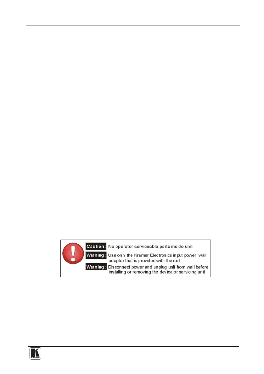
Servicing the machines can only be done by an authorized Kramer technician. Any user who makes changes or
modifications to the unit without the expressed ap proval of the manufacturer will void user authority to operate the
equipment.
Use the supplied DC power supply to feed power to the machine.
Please use recommended interconnection cables to connect the machine to other components.
12
Kramer
KRAMER: SIMPLE CREATIVE TECHNOLOGY
Page 15

For the latest information on our products and a list of Kramer
distributors, visit our Web site: www.kramerelectronics.com,
where updates to this user manual may be found.
We welcome your questions, comments and feedback.
Safety Warning:
Disconnect the unit from the power supply before
opening/servicing.
Caution
P/N:
2900- 000365
Rev:
3
Kramer Electronics, Ltd.
Web site: www.kramerelectronics.com
E-mail: info@kramerel.com
P/N: 2900-000365 REV 3
 Loading...