

Page 1

Kramer Electronics, Ltd.
Preliminary
USER MANUAL
Model:
TP-210A
UXGA – Audio – RS-232 Line Transmitter/DA
Page 2

Contents
Contents
1 Introduction 1
2 Getting Started 1
2.1 Quick Start 2
3 Overview 3
3.1 About the Power Connect Feature 3
3.2 Shielded Twisted Pair (STP)/Unshielded Twisted Pair (UTP) 4
3.3 Recommendations for Achieving the Best Performance 4
4 Your TP-210A UXGA – Audio – RS-232 Line Transmitter/DA 4
4.1 The TP-210A UXGA – Audio – RS-232 Line Transmitter/DA Underside 6
5 Installing on a Rack 7
6 Connecting the TP-210A 8
6.1 Wiring the CAT 5 LINE IN/LINE OUT RJ-45 Connectors 10
6.2 Wiring the RS-232 Connector 10
7 Technical Specifications 11
Figures
Figure 1: TP-210A UXGA – Audio – RS-232 Line Transmitter/DA 5
Figure 2: TP-210A Underside 6
Figure 3: Connecting the TP-210A UXGA – Audio – RS-232 Line Transmitter/DA 9
Figure 4: CAT 5 PINOUT 10
Figure 5: RS-232 PINOUT Connection 10
Tables
Table 1: TP-210A UXGA – Audio – RS-232 Line Transmitter/DA Features 6
Table 2: Features of the TP-210A Underside 6
Table 3: CAT 5 PINOUT 10
Table 4: Technical Specifications of the TP-210A 11
i
Page 3

Introduction
1 Introduction
Welcome to Kramer Electronics! Since 1981, Kramer Electronics has been
providing a world of unique, creative, and affordable solution s to the vast
range of problems that confront the video, audio, presentation, and
broadcasting professional on a daily basis. In recent years, we have
redesigned and upgraded most of our line, making the best even better! Our
1,000-plus different models now appear in 11 groups
1
that are clearly
defined by function.
Thank you for purchasing the Kramer TP-210A UXGA – Audio – RS-232
Line Transmitter/DA, which is ideal for:
• Presentation and multimedia applications
• Long range graphics distribution for schools, hospitals, security, and
stores
The package includes the following items:
• TP-210A UXGA – Audio – RS-232 Line Transmitter/DA
• Power cord
• This user manual
2
3
2 Getting Started
We recommend that you:
• Unpack the equipment carefully and save the original box and
packaging materials for possible future shipment
• Review the contents of this user manual
• Use Kramer high performance high-resolution cables
4
1 GROUP 1: Distribution Amplifiers; GROUP 2: Switchers and Matrix Switchers; GROUP 3: Control Systems;
GROUP 4: Format/Standards Converters; GROUP 5: Range Extenders and Repeaters; GROUP 6: Specialt y AV Products;
GROUP 7: Scan Converters and Scalers; GROUP 8: Cables and Connectors; GROUP 9: Room Connectivity;
GROUP 10: Accessories and Rack Adapters; GROUP 11: Sierra Products
2 We recommend that you use only the power cord supplied with this device
3 Download up-to-date Kramer user manuals from our Web site at http://www.kramerelectronics.com
4 The complete list of Kramer cables is on our Web site at http://www.kramerelectronics.com
1
Page 4
Getting Started
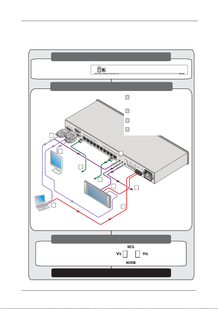
2.1 Quick Start
The quick start chart summarizes the basic setup and operation steps of the
TP-210A.
Step 1: Mount the machine - see section 5
Mount the machine in a rack or
Mount the machine in a rack or
stick the 4 rubber feet to the
stick the 4 rubber feet to the
underside
underside
Step 2: Connect the inputs and outputs - see section 6
Connect a computer graphics source to
Connect a computer graphics source to
1
the UXGA input, an audio source to the
the UXGA input, an audio source to the
audio input and RS-232 to the Rx, G port
TP-210A
UXGAINPUT
1
VGA
2
Display
VGA
1
Computer Graphics /
Audio / RS-232
Control
UXGAOUT 1
UXGAOUT2
CAT 5
4
To TP-124
OUT1
OUT2
Range up
100 meters)
STP Cable
To TP-124
Plasma
Display
OUT3
Audio
to 300ft
(up to
1
2
3
4
OUT4
LINE OUTPUTS
OUT5
OUT6
OUT7
OUT8
OUT9
OUT10
CAT 5
4
3
VGA
audio input and RS-232 to the Rx, G port
Connect the UXGA 1 video and audio
Connect the UXGA 1 video and audio
2
outputs, and the RS-232 port (if required)
outputs, and the RS-232 port (if required)
Connect the UXGA 2 video and audio
Connect the UXGA 2 video and audio
3
outputs, and the RS-232 port (if required)
outputs, and the RS-232 port (if required)
Connect to up to 10 TP-124 receivers via
Connect to up to 10 TP-124 receivers via
4
CAT 5
CAT 5
1
AA
NALOG UDIO
I
NPUT
O1
UT
O2
UT
S/PDIF
A
NALOG
S/PDIF
I
NPUT
O1
UT
O2
UT
RS-232
I
N
G R
O1
UT
X
GT
O
UT
X
2
GT
X
Audio
RS-232
2
To AV
Receiver
1
RS-232
Step 3: Set the underside switches - see section 6
Set the Hs and Vs
Set the Hs and Vs
polarity switches
polarity switches
Step 4: Connect the power
2
KRAMER: SIMPLE CREATIVE TECHNOLOGY
Page 5

3 Overview
Overview
The TP-210A UXGA – Audio – RS-232 Line Transmitter/DA receives a
computer graphics signal, an audio signal
1
and an RS-232 signal, and
distributes them to up to 10 receivers (via CAT 5 cables). The TP-210A
also simultaneously distributes the signal to two UXGA outputs, two analog
audio outputs or two digital audio outputs, and two RS-232 outputs.
The TP-210A serves as a power center that can distribute power to the
connected receivers (see section 3.1
).
In particular, the TP-210A features:
• A resolution of up to UXGA
• One UXGA input and two outputs on 15-pin HD computer graphics
video connectors
• One digital audio input and two outputs (S/PDIF) on RCA connectors
as well as one analog audio input and two outputs on 3.5mm mini jacks
• A transmission range of up to 300ft (up to 100 meters) over STP
cabling
• Changeable polarity for decoding H and V Sync for video (UXGA)
The TP-210A
is housed in a 19” 1U rack mountable enclosure, with rack “ears”
included, and is fed from a 100-240V AC universal switching power supply.
3.1 About the Power Connect Feature
The Power Connect feature applies as long as the cable can carry power.
This feature is available when using STP cable and the distance does not
exceed 50m on standard CAT 5 cable. For longer distances, heavy gauge
cable should be used
2
. For units which are connected via RJ-45 connectors,
make sure that the shield of the STP cable is connected to the metal casing
of the connectors on both ends of the cable. For units which are connected
via terminal block connectors, the shield of the STP cable must be
connected to a ground terminal on the units at both ends (use the ground
terminal of the power supply connection if necessary).
For a CAT 5 cable exceeding a distance of 50m, separate power suppli es
should be connected to the transmitter and to the receiver simultaneously.
1 Selectable analog or digital (S/PDIF) audio signal
2 CAT 5 cable is still suitable for the video/audio transmission, but not for feeding the power at these distances
3
Page 6

Your TP-210A UXGA – Audio – RS-232 Line Transmitter/DA
3.2 Shielded Twisted Pair (STP)/Unshielded Twisted Pair (UTP)
We recommend that you use Shielded Twisted Pair (STP) cable. There are
different levels of STP cable available, and we advise you to use the best
quality STP cable that you can afford. Our non-skew-free cable, Kramer
BC-STP is intended for analog signals where skewing is not an issue. For
cases where there is skewing, our UTP skew-free cable, Kramer BC-XTP,
may be used. Bear in mind, though, that we advise using STP cables where
possible, since the compliance to electromagnetic interference was tested
using those cables.
Although Unshielded Twisted Pair (UTP) cable might be preferred for long
range applications, the UTP cable should be installed far away from electric
cables, motors and so on, which are prone to cre ate electrical interference.
However, since the use of UTP cable might cause inconform ity to
electromagnetic standards, Kramer does not commit to meeting the standard
with UTP cable.
3.3 Recommendations for Achieving the Best Performance
hieve the best performance:
To ac
• Use only good quality connection cables
1
to avoid interference,
deterioration in signal quality due to poor matching, and elevated noise
levels (often associated with low quality cables).
• Avoid interference from neighboring electrical appliances that may
adversely influence signal quality and position your Kramer TP-210A
away from moisture, excessive sunlight and dust
4 Your TP-210A UXGA – Audio – RS-232 Line
Transmitter/DA
Figure 1 and Table 1 define the TP-210A:
1 Available from Kramer Electronics on our Web site at http://www.kramerelectronics.com
4
KRAMER: SIMPLE CREATIVE TECHNOLOGY
Page 7

Your TP-210A UXGA – Audio – RS-232 Line Transmitter/DA
Figure 1: TP-210A UXGA – Audio – RS-232 Line Transmitter/DA
5
Page 8

Your TP-210A UXGA – Audio – RS-232 Line Transmitter/DA
Table 1: TP-210A
# Feature Function
1 POWER Switch Illuminated switch for turning the unit ON or OFF
2 UXGA INPUT 15-pin HD Connector Connect to the video source
3 UXGA OUT 15-pin HD Connectors Connect to the video acceptor1
4 LINE OUTPUT RJ-45 Connectors1 Connect to2 the LINE IN RJ-45 connector o n a r e c e i v e r3
5
ANALOG AUDIO
3.5mm Mini Jacks
6
7 S/PDIF ANALOG Selector Button4 Press to select the analog audio source
8 S/PDIF RCA
Connectors
9
10 RS-232 Terminal
Block Connector
11 OUT (G, Tx1) Connect the two connectors (G and Tx) to control a device
12 Power Connector with Fuse AC connector enabling power supply to the unit
UXGA – Audio – RS-232 Line Transmitter/DA Features
INPUT
OUT
INPUT
OUT
IN (G, Rx)
Connect to the stereo analog audio source
Connect to the stereo analog audio acceptor1
Release to select the S/PDIF source
Connect to the digital audio source
Connect to the digital audio acceptor1
Connect the two connectors (G and Rx) to transmit a
command (see section 6.1
(see section 6.1
)
)
4.1 The TP-210A UXGA – Audio – RS-232 Line Transmitter/DA Underside
Figure 2
and Table 2 define the underside of the TP-210A
Figure 2: TP-210A Underside
Table 2: Features of the TP-210A Underside
Feature Function
VS Switch5 Slide the switch up, to set the VS to negative polarity (NEG.)
HS Switch5 Slide the switch up, to set the HS to negative polarity (NEG.)
Slide the switch down, to set the VS to its input polarity (NORM.)
Slide the switch down, to set the HS to its input polarity (NORM.)
1 From 1 to 2
2 Using a UTP CAT 5 cable with RJ-45 connectors at both ends (the PINOUT is defined in Table 3
3 For example, the Kramer TP-124 or TP-46
4 RS-232 can be embedded only when the S/PDIF ANALOG Selector Button is set to the analog state
5 By default, both switches are set to NORM.
6
and Figure 4)
KRAMER: SIMPLE CREATIVE TECHNOLOGY
Page 9

Installing on a Rack
5 Installing on a Rack
This section provides instructions for rack mounting the unit.
7
Page 10

Connecting the TP-210A
6 Connecting the TP-210A
This section describes how to connect the TP-210A (see section 6 ), wire the
CAT 5 LINE OUT RJ-45 Connectors (see section 6.1
connectors (see section 6.1
).
), and wire the RS-232
To connect the TP-210A, as illustrated in Figure 3
, do the following1:
1. Connect a UXGA source (for example, a laptop’s graphics card) to the
UXGA IN PUT 15-pin HD connector.
2. Connect an analog
example, using a Kramer C-GMA/GMA cable (VGA 15-pin HD +Audio
jack to VGA 15-pin HD +Audio jack)
2
audio source to the Audio I N 3.5mm mini jac k, for
3
, and press the S/PDIF – ANALOG
selector button.
3. Connect an RS-232 cable with a 9-pin D-sub connector at one end to the
laptop, and a 2-pin term inal block connect or at the othe r end to t he RS-232
IN port (G, Rx).
4. Connect the UXGA OUT 1 15-pin HD connector to the UXGA acceptor
(for example, a plasma display), and the ANALOG AUDIO
2
OUT 1
3.5mm mini jack connector to the analog audio connector on the acceptor. If
required, connect the RS-232 G and TX1 terminal block connector to the
RS-232 port on the acceptor.
5. Connect the UXGA OUT 2 15-pin HD connector to a UXGA acceptor (for
example, a display), and the ANALOG AUDIO
2
OUT 2 3.5mm mi ni jack
connector to the analog audio acceptor (for example, an AV Receiver).
4
6. Connect the LINE OUTPUT CAT 5 co nnectors as follo ws
The LINE OUT 1 RJ-45 connector on the TP-210A to the LINE IN
RJ-45 connector on a TP-124
of up to 300ft (up to 100m))
5
unit via UTP cabling6 (with a range
7
:
The LINE OUT 10 RJ-45 connector on the TP-210A to the LINE
IN RJ-45 connector on another TP-124, via UTP cabling (with a
range of up to 300ft (up to 100m))
1 Switch OFF the power on each device before connecting it to your TP-210A. After connecti ng your TP-210A, switch on i ts
power and then switch on the power on each device
2 Alternatively, you can connect a digital audio source and acceptors and release the S/PDIF – ANALOG selector button
3 Not supplied. The full list of Kramer cables is on our Web site at http://www.kramerelectronics.com
a UXGA source to the UXGA IN 15-pin HD connector, and a separate audio source to the AUDIO IN 3.5mm mini jack
4 You do not have to connect all the outputs
5 Refer to the separate user manual, which can be downloaded at http://www.kramerelectronics.com
6 For details of how to wire a CAT 5 LINE IN/LINE OUT RJ-45 connector, see section 6.1
7 Alternatively, you can connect the Kramer TP-46, which can be connected to an additional TP-46 unit for transmitting the
signal further
8
KRAMER: SIMPLE CREATIVE TECHNOLOGY
. You can also connect
Page 11

Connecting the TP-210A
7. Connect the power cord1.
8. If necessary, set the HS and VS switches
TP-210A
UXGA
INPUT
UXGA
OUT1
UXGAOUT 2
OUT1
OUT2
OUT3
OUT4
LINE OUTPUTS
OUT5
OUT6
OUT7
OUT8
OUT9
OUT10
XGA/ Audio / Data Line Receiver
Audio
RS-232
Display
VGA
Plasma
Display
VGA
RS-232
Range up
to 300ft
(up to
100 meters)
STP Cable
XGAOUT
VGA
LIN
INE
RS-232
GND
RS-232
Audio
Audio
TXD
Audio
TP-124
A
NALOG
AOUT
UDIO
S/PDIF
12VDC
TP-124
VGA
2
on the underside.
AA
NALOG UDIO
I
NPUT
O1
UT
O2
UT
S/PDIF
A
NALOG
S/PDIF
I
NPUT
O1
UT
O2
UT
Range up to 300ft
(up to 100 meters)
Audio
RS-232
I
N
G R
O1
UT
X
GT
O
UT
X
2
GT
X
STP Cable
VGA
TP-124
TP-124
XGAOUT
LIN
GND
INE
TXD
A
NALOG
RS-232
S/PDIF
AOUT
UDIO
12VDC
XGA/ Audio / Data Line Receiver
RS-232
Audio
Computer Graphics /
Audio / RS-232
Control
Plasma
Display
AV-Receiver
Plasma
Display
Figure 3: Connecting the TP-210A UXGA – Audio – RS-232 Line Transmitter/DA
1 We recommend that you use only the power cord that is supplied with this machine
2 By default, both switches are set down (for normal V SYNC and H SYNC polarity)
AV-Receiver
9
Page 12

Connecting the TP-210A
6.1 Wiring the CAT 5 LINE IN/LINE OUT RJ-45 Connectors
Table 3
and Figure 4 define the UTP CAT 5 PINOUT, using a straight pin
to pin cable with RJ-45 connectors:
Table 3: CAT 5 PINOUT
EIA /TIA 568A EIA /TIA 568B
PIN Wire Color PIN Wire Color
1 Green/White 1 Orange/White
2 Green 2 Orange
3 Orange/White 3 Green/White
4 Blue 4 Blue
5 Blue/White 5 Blue/White
6 Orange 6 Green
7 Brown/White 7 Brown/White
8 Brown 8 Brown
Pair 1 4 and 5 Pair 1 4 and 5
Pair 2 3 and 6 Pair 2 1 and 2
Pair 3 1 and 2 Pair 3 3 and 6
Pair 4 7 and 8 Pair 4 7 and 8
Figure 4: CAT 5 PINOUT
6.2 Wiring the RS-232 Connector
Prepare an RS-232 cable with a 9-pin D-sub connector at one end, and a 2-pin
terminal block connector at the other end, as defined in Figure 5
RS-232 to TP-210A
PIN 5 Connected to G
PIN 3 Connected to Rx
TP-210A to Controlled Unit
G PIN 5 Connected to
Tx Connected to PIN 2
:
10
5
9
4
8
3
7
2
6
1
PC (9-pin D-sub)
G
Rx
G
Tx
Figure 5: RS-232 PINOUT Connection
KRAMER: SIMPLE CREATIVE TECHNOLOGY
5
9
4
8
3
7
2
6
1
9-pin D-sub
Page 13

Technical Specifications
7 Technical Specifications
Table 4 includes the technical specifications1 of the TP-210A:
Table 4: Technical Specifications of the TP-210A
INPUTS: 1 UXGA video on a 15-pi n HD co nnector, 1 un balanced stere o audi o on a
OUTPUTS: 10 twisted pairs on RJ-45 connectors, 2 UXGA on 15-pin HD connectors, 2
MAX. OUTPUT LEVEL: Video: 1.6V; Audio: 2.3V.
POWER OUTPUTS: 12V DC 0.5A max via each RJ-45 output (PINs 4, 5)
RESOLUTION: UXGA & 1080p
BANDWIDTH: 20Hz to 20 kHz @1d B (audio)
SAMPLING RATE FOR S/PD IF : 48kHz
S/N RATIO: AUDIO: >75dB
TOTAL GAIN: AUDIO:
TND+N: AUDIO: <0.02%
POWER SOURCE: 100-240V AC, 50/60 Hz, 46VA
DIMENSIONS: 19" x 9.3" x 1U (W, D, H) rack mountable
WEIGHT: 3kg (6.6lbs) approx.
ACCESSORIES: Power cord2, rack “ears”
3.5mm mini jack, 1 S/PDIF on an RCA connector, 1 RS-232 with 1 RxD line
on a terminal block connector.
unbalanced stereo audio on 3.5mm mini jacks, 2 S/PDIF on RCA connectors,
2 RS-232 with 2 TxD lines on terminal block connectors.
Analog/analog: 0dB
Analog/SPDIF: -12dBFS
1 Specifications are subject to change without notice
2 We recommend that you use only the power cord that is supplied with this machine
11
Page 14

LIMITED WARRANTY
Kramer El ec t ro ni c s (hereafter ) warrants this product free from defects i n ma te rial and workmanship under the
following terms.
HOW LONG IS THE WARRANTY
Labor and parts are warranted for seven years from the date of the first customer purchase.
WHO IS PROTECTED?
Only the first purchase customer may enforce this warranty.
WHAT IS COVERED AND WHA T IS NO T COVERED
Except as below, this warranty covers all defects in material or workmanship in this product. The following are not covered
by the warranty:
1. Any product which is not distributed by Kramer, or which is not purchased from an authorized Kramer dealer. If you are
uncertain as to whether a dealer is authorized, please contact Kramer at one of the agents listed in the Web site
www.kramerelectronic s. com.
2. Any product, on which the serial number has been defaced, modified or removed, or on which the WARRANTY VOID
TAMPERED sticker has been torn,
IF reattached, removed or otherwise interfered with.
3. Damage, det erioratio n or malf unction resulting from:
i) Accident , misuse , abuse, ne glect, fi re, water , lightnin g or othe r acts of nat ure
ii) Product modification, or failure to follow instructions supplied with the product
iii) Repair or attemp ted repa ir by anyo ne not au thorized by Krame r
iv) Any shipment of the product (claims must be presented to the carrier)
v) Remo val or i nstallati on of the product
vi) Any other ca use, whic h does n ot relate t o a produ ct defect
vii) Cartons, equipment enclosures, cables or accessories used in conjunction with the product
WHAT WE WILL PAY FOR AND WHAT WE WILL NOT PAY FOR
W e will pay l abor an d mater ial expense s for cov ered ite ms. W e wi ll not pa y for the followin g:
1. Removal or installations charges.
2. Co sts of initial technical adjustments (set-up), including adjustment of user controls or programming. These costs are the
responsi bility of the Kram er deal er from wh om the pr oduct w as purcha sed.
3. Shipping charges.
HOW YOU CAN GET WARRANTY SERVICE
1. To obtain service on you product, you must take or ship it prepaid to any authorized Kramer service center.
2. Whenever warranty service is required, the original dated invoice (or a copy) must be presented as proof of warranty
coverage, and should be included in any shipment of the product. Please also include in any mailing a contact name,
company, address, and a description of the problem(s).
3. For the name of the nearest Kramer authorized service center, consult your authorized dealer.
LIMITATION OF IMPLIED WARRANTIES
All implied warranties, including warranties of merchantability and fitness for a particular purpose, are limited in duration to
the length of this warranty.
EXCLUSION OF DAMAGES
The liability of Kramer for any effective products is limited to the repair or replacement of the product at our option. Kramer shall
not be liabl e for:
1. Damage to other pr operty cau sed by defe cts in th is product , damages based upo n inconven ience , loss of use o f the produ ct, loss
of time, commercial loss; or:
2. Any other dam ages , whe ther i nci den tal, co nseq uen tial o r o ther wise. Som e co untri es ma y n ot a llow limit ati ons o n ho w lon g an
implied warranty lasts and/or do not allow the exclusion or limitation of incidental or consequential damages, so the above
limita tions a nd exc lusio ns may not a pply to you.
This warranty gives you specific legal rights, and you may al so have other rights, which vary from place to pla ce.
NOTE:
All products returned to Kramer fo r service must have prior approval. This m ay be obtained from your dealer .
This equipment has been tested to determine compliance with the requ irements of:
EN-50081: "Electromagnetic compatibility (EMC);
Residential, commer cial and light industry"
EN-50082: "Electromagnetic compatibility (EMC) generic immunity standard.
CFR-47: FCC* Rules and Regulations:
CAUTION!
generic emission standard.
Part 1:
Part 1: Residential, commercial and light industry environment".
Part 15: “Radio frequency devices
Subpart B Unintentional radiators”
Servicing the machines can only be done by an authorized Kramer technician. Any user who makes changes or
modifications to the unit without the expressed approval of the manufacturer will v oid user authority to operate the
equipment.
Use the supplied DC power supply to feed power to the machine.
Please use recommended interconnection cables to connect the machine to other compo nents.
* FCC and CE approved u sing STP c able (for tw isted pai r products )
Kramer
12
KRAMER: SIMPLE CREATIVE TECHNOLOGY
Page 15

For the latest information on our products and a list of Kramer
distributors, visit our Web site: www.kramerelectronics.com,
where updates to this user manual may be found.
We welcome your questions, comments and feedback.
Safety Warning:
Disconnect the unit from the power supply before
opening/servicing.
Caution
P/N:
2900-000367
Rev:
3
Kramer Electronics, Ltd.
Web site: www.kramerelectronics.com
E-mail: info@kramerel.com
P/N: 2900-000367 REV 3
 Loading...