

Page 1

Kramer Electronics, Ltd.
Preliminary
USER MANUAL
Models:
PT-110-od and TP-120-od XGA Line Transmitter, Receiver
TP-121-od and TP-122-od XGA/Audio Line Transmitter, Receiver
TP-123-od and TP-124-od XGA/Audio/Data Line Transmitter, Receiver
TP-125-od and TP-126-od XGA/Audio/Data Line Transmitter, Receiver
Page 2

Contents
Contents
1 Introduction 1
2 Getting Started 1
2.1 Quick Start 2
3 Overview 3
3.1 Shielded Twisted Pair (STP) / Unshielded Twisted Pair (UTP) 3
3.2 About the Power Connect™ Feature 4
3.3 Defining EDID 4
3.4 Recommendations for Achieving the Best Performance 4
4 The PT-110-od / TP-120-od Transmitter / Receiver Set 5
4.1 Your PT-110-od XGA / Line Transmitter 6
4.2 Your TP-120-od XGA Line Receiver 7
4.3 Connecting the PT-110-od / TP-120-od Transmitter / Receiver 8
4.4 Technical Specifications of the PT-110-od and the TP-120-od 10
5 The TP-121-od / TP-122-od Transmitter / Receiver Set 11
5.1 Your TP-121-od XGA / Audio Line Transmitter 12
5.2 Your TP-122-od XGA / Audio Line Receiver 13
5.3 Connecting the TP-121-od / TP-122-od Transmitter / Receiver 14
5.4 Technical Specifications of the TP-121-od and the TP-122-od 16
6 The TP-123-od / TP-124-od Transmitter / Receiver Set 17
6.1 Your TP-123-od XGA / Audio / Data Line Transmitter 18
6.2 Your TP-124-od XGA / Audio Line Receiver 19
6.3 Connecting the XGA / Audio / Data Line Transmitter / Receiver 20
6.4 Controlling via RS-232 (for example, using a PC) 22
6.5 Technical Specifications of the TP-123-od and the TP-124-od 23
7 The TP-125-od / TP-126-od Transmitter / Receiver Set 24
7.1 Your TP-125-od XGA / Audio / Data Line Transmitter 25
7.2 Your TP-126-od XGA / Audio / Data Line Receiver 26
7.3 Connecting the TP-125-od and TP-126-od 27
7.4 Transmitting via RS-232 (for example, using a PC) 29
7.5 Technical Specifications 30
8 Wiring the CAT 5 LINE IN / LINE OUT RJ-45 Connectors 31
9 Acquiring the EDID 31
i
Page 3

Contents
Figures
Figure 1: PT-110-od XGA Line Transmitter 6
Figure 2: TP-120-od XGA Line Receiver 7
Figure 3: Connecting the PT-110-od to the TP-120-od 9
Figure 4: TP-121-od XGA / Audio Line Transmitter 12
Figure 5: TP-122-od XGA / Audio Line Receiver (Topside) 13
Figure 6: Connecting the TP-121-od and the TP-122-od 15
Figure 7: TP-123-od XGA / Audio / Data Line Transmitter 18
Figure 8: TP-124-od XGA / Audio / Data Line Receiver (Topside) 19
Figure 9: Connecting the TP-123-od and the TP-124-od 21
Figure 10: RS-232 PINOUT Connection 22
Figure 11: TP-125-od XGA / Audio / Data Line Transmitter 25
Figure 12: TP-126-od XGA / Audio / Data Line Receiver 26
Figure 13: Connecting the TP-125-od and the TP-126-od 28
Figure 14: RS-232 PINOUT Connection 29
Figure 15: CAT 5 PINOUT 31
Tables
Table 1: PT-110-od XGA Line Transmitter Features 6
Table 2: TP-120-od XGA Line Receiver Features 7
Table 3: Technical Specifications of the PT-110-od and the TP-120-od 10
Table 4: TP-121-od XGA / Audio Line Transmitter Features 12
Table 5: TP-122-od XGA / Audio Line Receiver (Topside) Features 13
Table 6: Technical Specifications of the TP-121-od and the TP-122-od 16
Table 7: TP-123-od XGA / Audio / Data Line Transmitter Features 18
Table 8: TP-124-od XGA / Audio / Data Line Receiver (Topside) Features 19
Table 9: RS-232 PINOUT Connection 22
Table 10: Technical Specifications of the TP-123-od and the TP-124-od 23
Table 11: TP-125-od XGA / Audio / Data Line Transmitter Features 25
Table 12: TP-126-od XGA / Audio / Data Line Receiver Features 26
Table 13: RS-232 PINOUT Connection 29
Table 14: Technical Specifications of the TP-125-od and the TP-126-od 30
Table 15: CAT 5 PINOUT 31
ii
KRAMER: SIMPLE CREATIVE TECHNOLOGY
Page 4

Introduction
1 Introduction
Welcome to Kramer Electronics! Since 1981, Kramer Electronics has been
providing a world of unique, creative, and affordable solutions to the vast range
of problems that confront the video, audio, presentation, and broadcasting
professional on a daily basis. In recent years, we have redesigned and upgraded
most of our line, making the best even better! Our 1,000-plus different m odels
now appear in 11 groups
1
that are clearly defined by function.
Thank you for purchasing your Kramer transmitter and receiver set that
includes special protection against EMP
2
. The “od3 series” sets that are
available include the:
• PT-110-od XGA Line Transmitter and TP-120-od XGA Line Receiver
• TP-121-od XGA / Audio Line Transmitter and TP-122-od XGA / Audio
Line Receiver
• TP-123-od XGA / Audio / Data Line Transmitter and TP-124-od XGA /
Audio / Data Line Receiver
• TP-125-od XGA / Audio / Data Line Transmitter and TP-126-od XGA /
Audio / Data Line Receiver
Each “od series” set is ideal for presentation and multimedia applications.
The package includes:
• One or more of the following: PT-110-od, TP-120-od, TP-121-od,
TP-122-od, TP-123-od, TP-124-od, TP-125-od or TP-126-od
4
• Power adapter (12V DC) and this user manual
2 Getting Started
We recommend that you:
• Unpack the equipment carefully and save the original box and packaging
materials for possible future shipment
• Review the contents of this user manual
• Use Kramer high-performance high-resolution cables
5
1 GROUP 1: Distribution Amplifiers; GROUP 2: Switchers and Matrix Switchers; GROUP 3: Control Systems; GROUP 4:
Format/Standards Converters; GROUP 5: Range Extenders and Repeaters; GROUP 6: Specialt y AV Products; GROUP 7:
Scan Converters and Scalers; GROUP 8: Cables and Connectors; GROUP 9: Room Conn ectivity; GROUP 10: Accessories
and Rack Adapters; GROUP 11: Sierra Products
2 Electromagnetic Pulse
3 Overvoltage Defense
4 Download up-to-date Kramer user manuals at http://www.kramerelectronics.com
5 The complete list of Kramer cables is on our Web site at http://www.kramerelectronics.com
1
Page 5
Getting Started
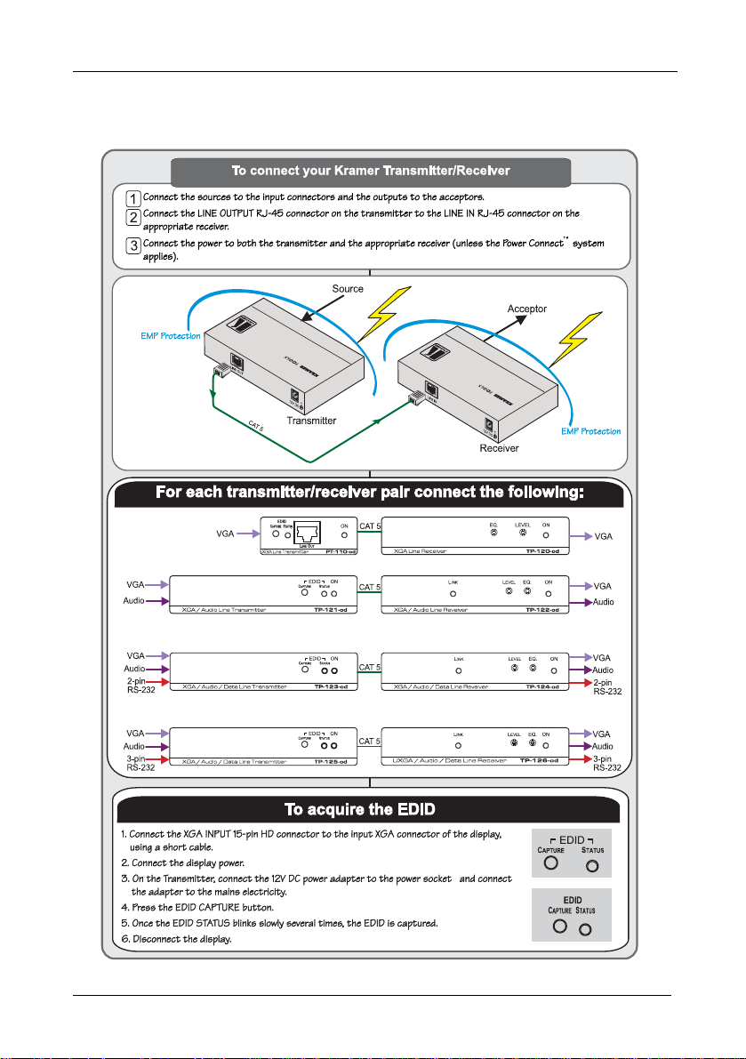
2.1 Quick Start
This quick start chart summarizes the basic setup and operation steps.
2
KRAMER: SIMPLE CREATIVE TECHNOLOGY
Page 6

Overview
3 Overview
Kramer’s new “od” (Overvoltage Defense) family of twisted pair transmitters
and receivers for computer graphics video now includes electromagnetic
pulse (EMP) protection. The electro-magnetic pulse of nearby lightning
strikes can damage sensitive electronic equipment by inducing high
momentary surge voltages. Systems with outdoor runs of signal cable are
very susceptible to EMP damage. Our “od” family was especially designed to
protect twisted pair transmitter/receiver systems installed in areas of high
electrical storm activity.
Note, that the “od” family is designed for indoor installation and should
be suitably protected against direct lightning strikes. The system does not
protect against direct lightning strikes and does not offer protection against
damage caused by lightning to peripheral devices that are connected to an “od
series” transmitter/receiver set.
This user manual describes the following lightning protected transmitter
receiver sets:
• PT-110-od / TP-120-od XGA Line Transmitter / Receiver (see section 4
• TP-121-od / TP-122-od XGA / Audio Line Transmitter / Receiver (see
section 5
• TP-123-od / TP-124-od XGA / Audio / Data Line Transmitter / Receiver
(see section 6
• TP-125-od / TP-126-od XGA / Audio / Data Line Transmitter / Receiver
(see section 7
)
)
)
)
This section describes:
• Using shielded twisted pair (STP) / unshielded twisted pair (UTP), see
section 3.1
• The power connect feature, see section 3.2
• Defining EDID, see section 3.3
• Recommendations for achieving the best performance, see section 3.4
3.1 Shielded Twisted Pair (STP) / Unshielded Twisted Pair (UTP)
We
recommend that you use Shielded Twisted Pair (STP) cable. There are
different levels of STP cable available, and we advise you to use the best
quality STP cable that you can afford. Our non-skew-free cable, Kramer
BC-STP is intended for analog signals where skewing is not an issue. For
cases where there is skewing, our UTP skew-free cable, Kramer BC-XTP,
may be used. Bear in mind, though, that we advise using STP cables where
possible, since the compliance to electromagnetic interference was tested
using those cables.
3
Page 7

Overview
Although Unshielded Twisted Pair (UTP) cable might be preferred for long range
applications, the UTP cable should be installed far away from electric cables, motors
and so on, which are prone to create electrical interference.
However, since the use of UTP cable might cause inconformity to electromagnetic
standards, Kramer does not commit to meeting the standard with UTP cable.
3.2 About the Power Connect™ Feature
The Power Connect feature applies as long as the cable can carry power. This
feature is available when using STP cable and the distance does not exceed 50m
on standard CAT 5 cable. For longer distances, heavy gauge cable should be
1
. For units which are connected via RJ-45 connectors, make sure that the
used
shield of the STP cable is connected to the metal casing of the connectors on both
ends of the cable. For units which are connected via terminal block connectors,
the shield of the STP cable must be connected to a ground terminal on the units at
both ends (use the ground terminal of the power supply connection if necessary).
For a CAT 5 cable exceeding a distance of 50m, separate power supplies should
be connected to the transmitter and to the receiver simultaneously.
3.3 Defining EDID
The PT-110-od, TP-121-od, TP-123-od, and TP-125-od include:
• EDID Capture - Copies and stores the EDID from a display device
The Extended Display Identification Data (EDID
2
) is a data-structure, provided
by a display, to describe its capabilities to a graphics card (that is connected to the
display’s source). The EDID enables the graphic source to “know” what kind of
monitor is connected to the output. The EDID includes the manufacturer’s name,
the product type, the timing data supported by the display, the display size,
luminance data and (for digital displays only) the pixel mapping data.
3.4 Recommendations for Achieving the Best Performance
To achieve the best performance:
• Use only good quality connection cables
3
to avoid interference, deterioration
in signal quality due to poor matching, and elevated noise levels (often
associated with low quality cables).
• Avoid interference from neighboring electrical appliances that may adversely
influence signal quality and position your Kramer transmitters away from
moisture, excessive sunlight and dust
1 CAT 5 cable is still suitable for the video/audio transmission, but not for feeding the power at these distances
2 Defined by a standard published by the Video Electronics Standards Association (VESA)
3 Available from Kramer Electronics on our Web site at http://www.kramerelectronics.com
4
KRAMER: SIMPLE CREATIVE TECHNOLOGY
Page 8

The PT-110-od / TP-120-od Transmitter / Receiver Set
4 The PT-110-od / TP-120-od Transmi tter / Re ceiver Set
The Kramer Pico TOOLS PT-110-od is an XGA line transmitter that receives
an XGA signal (up to UXGA), converts it to a twisted pair signal, and
transmits it over a CAT 5 cable to the Kramer TOOLS TP-120-od receiver
which converts it back to an XGA signal. Together the PT-110-od and
TP-120-od form a computer graphics transmitter/receiver system.
The transmitter receiver system has an operating range of more than 300ft
(more than 100m) using standard CAT 5 cable, has the Power Connect
1
feature
and is 12V DC fed.
The PT-110-od is pre-programmed with default EDID settings with EDID
information ready for the source even before capturing the EDID from the
display. When the PT-110-od is connected to a display device and the EDID
CAPTURE button is pressed, the PT-110-od reads and stores the EDID
(Extended Display Identification Dat a) from the display device. The display
can be disconnected and later reconnected without rebooting the operating
system.
The TP-120-od includes EQ. and LEVEL controls.
1 Powering via the CAT 5 cable from either the receiver or the transmitter is good for 50 meters. Above it, both sides should
be fed with power
5
Page 9
The PT-110-od / TP-120-od Transmitter / Receiver Set
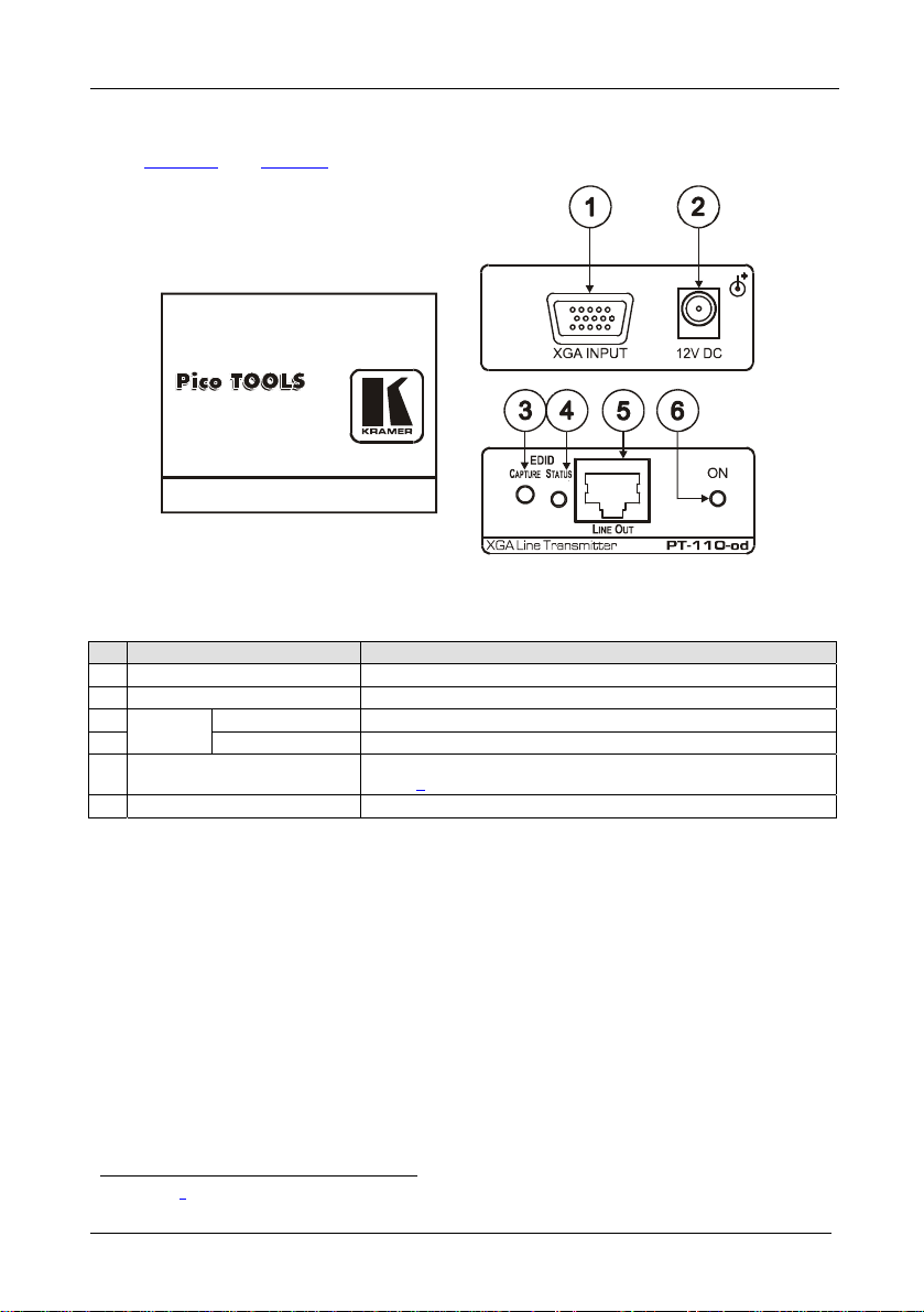
4.1 Your PT-110-od XGA / Line Transmitter
Figure 1
and Table 1 define the PT-110-od:
Figure 1: PT-110-od XGA Line Transmitter
Table 1: PT-110-od XGA Line Transmitter Features
# Feature Function
1 XGA IN 15-pi n H D (F) C o n n e c t o r Connect to the UXGA source
2
12V DC
1
3
EDID
4 STATUS LED Illuminates during normal operation; blinks when acquiring the EDID
5 LINE OUT RJ-45 Connector Connects to the LINE IN RJ-45 connector o n t h e TP-120 -od (see
6 ON LED Illuminates when receiving power
CAPTURE Button Press to acquire the EDID information from the display
+12V DC connector for powering the unit
)
section 8
1 See section 9
6
KRAMER: SIMPLE CREATIVE TECHNOLOGY
Page 10
The PT-110-od / TP-120-od Transmitter / Receiver Set
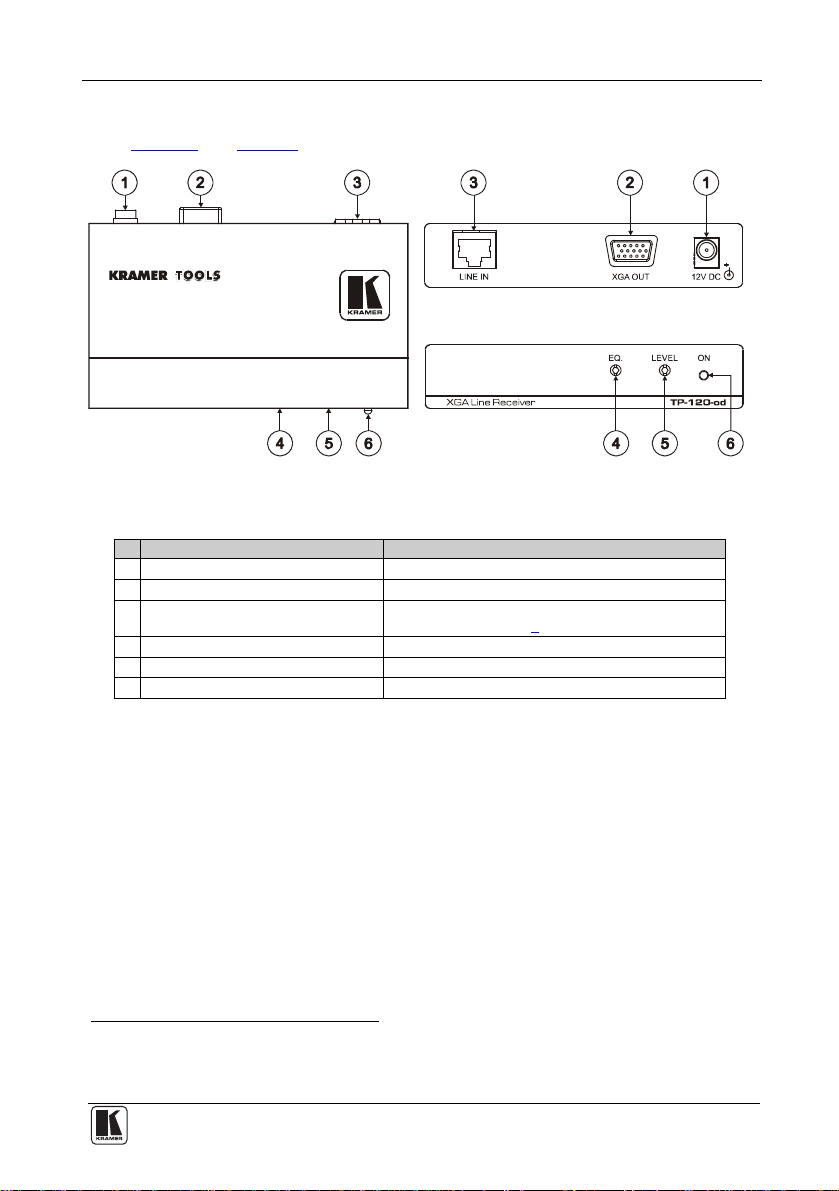
4.2 Your TP-120-od XGA Line Receiver
Figure 2
and Table 2 define the TP-120-od XGA Line Receiver:
Figure 2: TP-120-od XGA Line Receiver
Table 2: TP-120-od XGA Line Receiver Features
# Feature Function
1
12V DC
2 XGA OUT 15-pin HD (F) Connector Connect to the XGA acceptor
3 LINE IN RJ-45 Connector Connects to the LINE OUT RJ-45 connector on the
4 EQ.1 Trimmer Adjusts2 the cable compensation equalization level
5 LEVEL Trimmer Adjusts2 the output signal level
6 ON LED Illuminates when receiving power
+12V DC connector for powering the unit
PT-110-od (see section 8
)
1 Degradation and VGA/XGA signal loss can result from using long c ables (due to stray capacitance), sometimes leading to a
total loss of sharpness in high-resolution signals
2 Use a screwdriver to carefully rotate the trimmer, adjusting the appropriate level
7
Page 11

The PT-110-od / TP-120-od Transmitter / Receiver Set
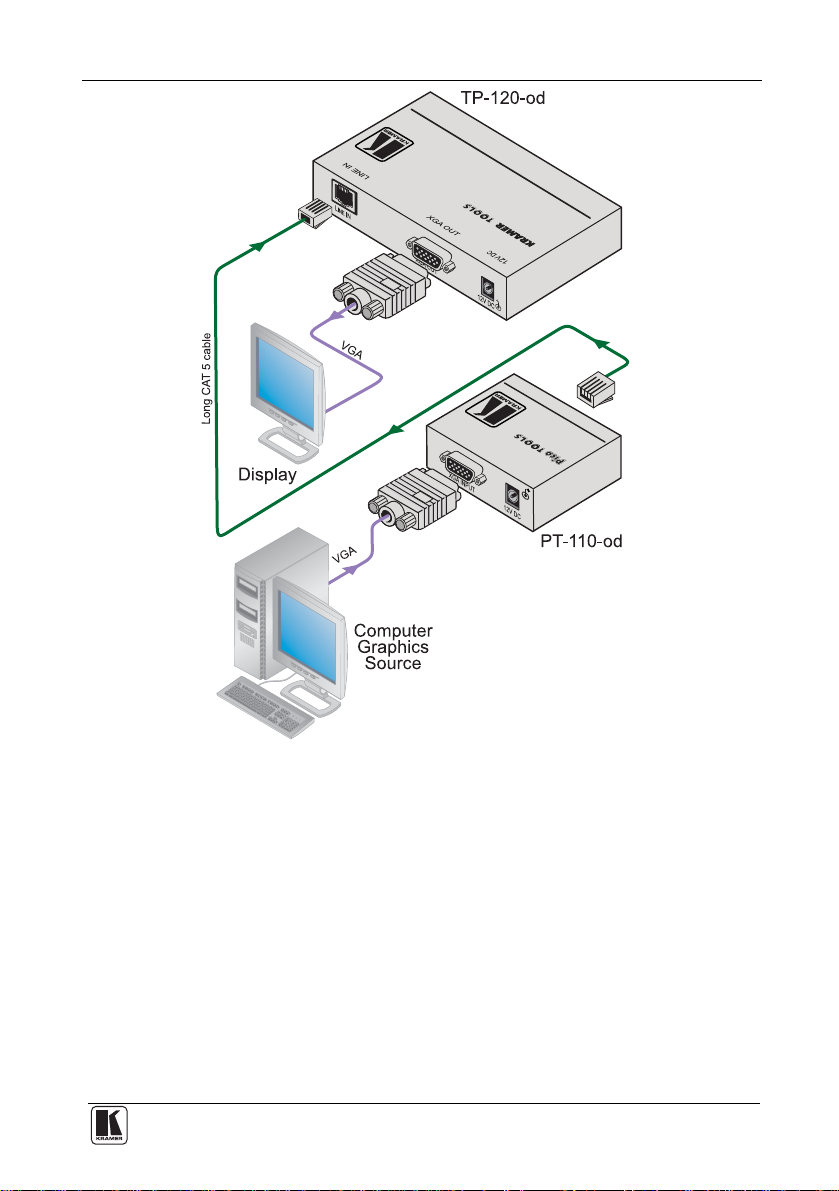
4.3 Connecting the PT-110-od / TP-120-od Transmitter / Receiver
You can use the PT-110-od XGA Line Transmitter
together with the
TP-120-od XGA Line Receiver to configure an XGA-to-Twisted Pair
Transmitter and Receiver system.
Before connecting the transmitter and receiver system you can acquire the
EDID (via PT-110-od) from the display or set the system to the default EDID,
see section 9
To connect the PT-110-od XGA Line Transmitter with the TP-120-od XGA
Line Receiver, as the example in Figure 3
illustrates, do the following:
1. On the PT-110-od, connect the XGA source (for example, the 15-pin HD
output from a computer’s graphics card) to the XGA INPUT 15-pin HD
(F) connector.
2. On the TP-120-od, connect the XGA OUT 15-pin HD (F) connector to
the XGA acceptor (for example, a display).
3. Connect the LINE OUTPUT RJ-45 connector on the PT-110-od to the
LINE IN RJ-45 connector on the TP-120-od, via CAT 5 cabling (with a
range of more than 300ft (>100m)), see section 8
4. On both
1
the PT-110-od and the TP-120-od, connect the 12V DC power
.
adapter to the power socket and connect the adapter to the mains
electricity.
The signal from the XGA source is transmitted via CAT 5 cable, decoded
and converted at the XGA OUT 15-pin HD (F) connector to the XGA
acceptor.
2
5. If required, on the TP-120-od, adjust
the output signal level and/or cable
compensation equalization level.
1 For distances of up to 100 meters you can connect a power adapter to either the PT-110-od or TP-120-od. Abo ve it, both
sides should be fed with power
2 Use a screwdriver to carefully rotate the trimmer, adjusting the appropriate level
8
KRAMER: SIMPLE CREATIVE TECHNOLOGY
Page 12
The PT-110-od / TP-120-od Transmitter / Receiver Set
Figure 3: Connecting the PT-110-od to the TP-120-od
9
Page 13

The PT-110-od / TP-120-od Transmitter / Receiver Set
4.4 Technical Specifications of the PT-110-od and the TP-120-od
Table 3
includes the technical specifications1 of the PT-110-od and the
TP-120-od:
Table 3: Technical Specifications2 of the PT-110-od and the TP-120-od
PT-110-od TP-120-od
INPUTS: VIDEO: 1 VGA / UXGA on a 15-pin HD
connector
OUTPUTS: 1 RJ-45 connector VIDEO: 1 VGA / UXGA on a 15-pin HD
MAX. OUTPUT LEVEL: 1.7Vpp
BANDWIDTH: 150MHz
RESOLUTION: Up to UXGA
DIFF. GAIN: 1.6%
DIFF PHASE: 0.2 Deg.
K-FACTOR: <0.05%
S/N RATIO: 70dB @5MHz
CONTROLS: LEVE L : -9 dB to +2. 5dB
COUPLING: AC
POWER SOURCE: 12V D C 300 m A 12V DC 240m A
DIMENSIONS: 12.1cm x 7.18cm x 2.42cm (4.76" x 2.83" x 0.9 5") W, D, H
WEIGHT: 0.3kg (0.67lbs) approx.
ACCESSORIES: Power supply
OPTIONS: RK-4PT rack adapter RK-3T rack adapter
1 RJ-45 connector
connector
EQ.: 0dB to +31dB
1 The measurements are presented for the transmitter/receiver pair
2 Specifications are subject to change without notice
10
KRAMER: SIMPLE CREATIVE TECHNOLOGY
Page 14

The TP-121-od / TP-122-od Transmitter / Receiver Set
5 The TP-121-od / TP-122-od Transmitter / Receiver Set
The Kramer TOOLS TP-121-od is an XGA / audio stereo line transmitter. It
receives an XGA signal and an unbalanced stereo analog audio signal
converts them to a twisted pair signal and transmits them over CAT 5 cable to
the Kramer TOOLS TP-122-od.
The TP-121-od, with the TP-122-od, provides an operation range of more
than 300ft (more than 100m) over standard CAT 5 cable, has the Power
Connect feature
2
and is 12V DC fed.
The TP-121-od:
• Has a 20kHz audio bandwidth with an S/N ratio that exceeds 80dB on the
same transmission range
• When connected to a display device and the EDID CAPTURE button is
pressed, reads and stores the EDID (Extended Display Identification Data)
from the display device. The display can be disconnected and later
reconnected without rebooting the operating system
In addition, the TP-122-od:
• Includes EQ. and level controls
This section defines the TP-121-od XGA / Audio Line Transmitter (see
section 5.1
), and the TP-122-od XGA / Audio Line Receiver (see section 5.2).
1
1 The unbalanced stereo analog audio signal is converted to digital audio (S/PDIF) stream before transmitting, thus preserving
the quality of the audio signal
2 Powering via the CAT 5 cable from either the receiver or the transmitter is good for 50 meters. Above it, both sides should
be fed with power
11
Page 15

The TP-121-od / TP-122-od Transmitter / Receiver Set
5.1 Your TP-121-od XGA / Audio Line Transmitter
Figure 4
and Table 4 define the TP-121-od:
Figure 4: TP-121-od XGA / Audio Line Transmitter
Table 4: TP-121-od XGA / Audio Line Transmitter Features
# Feature Function
1
12V DC
2 AUDIO IN 3.5mm Mini Jack Connects to the audio source
3 LINE OUT RJ-45 Connector Connects to the LINE IN RJ-45 connector o n a r e c e i v e r
4 XGA IN 15-pin HD (F) Connector Connect to the XGA source
5
6 STATUS LED Illuminates during normal operation; blinks when
7 ON LED Illuminates when receiving power
EDID
1
CAPTURE Button Press to acquire the EDID information from the display
+12V DC connector for powering the unit
(see section 8
acquiring the EDID
)
1 See section 9
12
KRAMER: SIMPLE CREATIVE TECHNOLOGY
Page 16

The TP-121-od / TP-122-od Transmitter / Receiver Set
5.2 Your TP-122-od XGA / Audio Line Receiver
Figure 5
and Table 5 define the TP-122-od XGA / Audio Line Receiver
topside:
Figure 5: TP-122-od XGA / Audio Line Receiver (Topside)
Table 5: TP-122-od XGA / Audio Line Receiver (Topside) Features
# Feature Function
1
12V DC
2
AUDIO
3 ANALOG 3.5mm Mini
OUT
4 LINE IN RJ-45 Connector Connects to the TP-121-od (see section 8)
5 XGA OU T 15-pin HD (F ) Co n n ecto r Connects to the XGA acceptor
6 LINK LED Illuminates when receiving the correct input signal
7 LEVEL Trimmer Adjusts2 the output signal level
8 EQ.1 Trimmer Adjusts2 the cable compensation equalization level
9 ON LED Illuminates when receiving power
S/PDIF RCA Connector Connects to the digital audio acceptor
Jack
+12V DC connector for powering the unit
Connects to the analog audio acceptor
1 Degradation and VGA/XGA signal loss can result from using long c ables (due to stray capacitance), sometimes leading to a
total loss of sharpness in high-resolution signals
2 Use a screwdriver to carefully rotate the trimmer, adjusting the appropriate level
13
Page 17

The TP-121-od / TP-122-od Transmitter / Receiver Set
5.3 Connecting the TP-121-od / TP-122-od Transmitter / Receiver
You can use the TP-121-od together with the TP-122-od to configure an
XGA/Audio Line-to-Twisted Pair Transmitter and Receiver system.
Before connecting the transmitter and receiver system you can acquire the
EDID (via TP-121-od) from the display or set the system to the default EDID,
see section 9
To connect the TP-121-od XGA / Audio Line Transmitter with the TP-122-od
XGA / Audio Line Receiver, as the example in Figure 6
illustrates, do the
following:
1. On the TP-121-od, connect the XGA source (for example, a laptop’s
graphics card) to the XGA INPUT 15-pin HD (F) connector and an audio
source to the AUDIO IN 3.5mm mini jack, for example, using a Kramer
C-GMA/GMA cable (VGA 15-pin HD (M) +Audio jack to VGA 15-pin HD
(M) +Audio jack)
1
. Alternatively, you can connect an XGA source to the
XGA INPUT 15-pin HD (F) connector, and a separate audio source to the
AUDIO IN 3.5mm mini jack.
2. On the TP-122-od, connect the XGA OUT 15-pin HD (F) connector to
the XGA acceptor (for example, a display), and connect the AUDIO OUT
S/PDIF RCA connector to the digital audio acceptor (for example, an AV
Receiver), and the ANALOG 3.5mm mini jack to the analog audio
acceptor (for example, a stereo audio recorder).
3. Connect the LINE OUTPUT RJ-45 connector on the TP-121-od to the
LINE IN RJ-45 connector on the TP-122-od, via CAT 5 cabling (with a
range of more than 300ft (>100m)), see section 8
4. Connect the 12V DC power adapter to the power socket and connect the
adapter to the mains electricity on both
2
the TP-121-od and the TP-122-od.
.
The signal from the XGA source is transmitted via CAT 5 cable, decoded and
converted at the XGA OUT 15-pin HD (F) connector to the XGA acceptor.
3
5. If required, on the TP-122-od adjust
the video output signal level and/or
cable compensation equalization level.
1 Not supplied. The complete list of Kramer cables is on our Web site at http://www.kramerelectronics.com
2 If you cannot connect the power to both the TP-121-od and TP-122-od, you can just connect the power to the TP-122-od
3 Use a screwdriver to carefully rotate the trimmer, adjusting the appropriate level
14
KRAMER: SIMPLE CREATIVE TECHNOLOGY
Page 18

The TP-121-od / TP-122-od Transmitter / Receiver Set
Figure 6: Connecting the TP-121-od and the TP-122-od
15
Page 19

The TP-121-od / TP-122-od Transmitter / Receiver Set
5.4 Technical Specifications of the TP-121-od and the TP-122-od
Table 6
includes the technical specifications1 of the TP-121-od and the
TP-122-od.
Table 6: Technical Specifications2 of the TP-121-od and the TP-122-od
TP-121-od TP-122-od
INPUTS: VIDEO: 1 VGA / UXGA on a 15-pin HD
OUTPUTS: 1 RJ-45 connector VIDEO: 1 VGA / UXGA on a 15-pin HD
MAX. O U T P U T LEVEL: VI D E O : 1 .8 V; AUDIO: 2.9Vpp
BANDWIDTH (-3dB): AUDIO: 21kHz; VIDEO: 150MHz
RESOLUTION: Up to UXGA
DIFF. GAIN: 1.8%
DIFF. PHASE: 0.3 DEG.
K-FACTOR: <0.05%
S/N RATIO: VIDEO: 62dB @5MHz
CROSSTALK (all
hostile):
CONTROLS (VIDEO): LEVEL, -8.5dB to 3.2dB
COUPLING: VIDEO: AC
AUDIO THD + NOISE: 0.2% @1kHz
AUDIO 2nd HARMONIC: 0.01% @1kHz
POWER SOURCE: 12V DC 380mA 12V DC 350mA
DIMENSIONS: 12.1cm x 7.18cm x 2.42cm (4.76" x 2.83" x 0.9 5") W, D, H
WEIGHT: 0.3kg (0.67lbs) approx.
ACCESSORIES: Power supply
OPTIONS: RK-3T rack adapter
connector
AUDIO: 1 analog unbalanced stereo
audio on a 3.5mm mini jack
AUDIO: 69dB @1kHz
VIDEO: -58dB, video into audio
AUDIO: AC
1 RJ-45 connector
connector
AUDIO:
1 audio S/PDIF on an RCA connector
1 analog unbalanced stereo audio on a
3.5mm mini jack
EQ.: 0dB to 31.5dB
VIDEO: AC
AUDIO: IN – AC, OUT – DC
1 The measurements are presented for the transmitter/receiver pair
2 Specifications are subject to change without notice
16
KRAMER: SIMPLE CREATIVE TECHNOLOGY
Page 20

The TP-123-od / TP-124-od Transmitter / Receiver Set
6 The TP-123-od / TP-124-od Transmitter / Receiver Set
The TP-123-od is a high-performance transmitter. It accepts a computer
graphics input signal, an unbalanced stereo analog audio signal
1
,
unidirectional (RxD) RS-232 control commands and 12V DC power, over
CAT 5 cable, and transmits to the TP-124-od. The TP-123-od can power or
be powered by the TP-124-od transmitter over the same CAT 5 cable and is
12V DC fed.
The TP-124-od outputs a computer graphics signal, an unbalanced stereo
analog audio signal, a converted digital audio (S/PDIF) signal and RS-232
control commands. The unidirectional (TxD) RS-232 interface makes it
possible to control virtually any devices over a transmission range of more
than 300ft (more than 100m) over UTP cabling.
When the TP-123-od is connected to a display device and the EDID
CAPTURE button is pressed, the TP-123-od reads and stores the EDID
(Extended Display Identification Dat a) from the display device. The display
can be disconnected and later reconnected without rebooting the operating
system.
In addition, the TP-124-od features:
• Level and EQ. control for the XGA signals
• 24 bit 48kHz S/PDIF digital audio that supplies the highest quality audio
1 The stereo analog audio signal is converted to the digital audio (S/PDIF) stream before transmitting, thus preserving the
quality of the audio source signals
17
Page 21

The TP-123-od / TP-124-od Transmitter / Receiver Set
6.1 Your TP-123-od XGA / Audio / Data Line Transmitter
Figure 7
and Table 7 define the TP-123-od:
Figure 7: TP-123-od XGA / Audio / Data Line Transmitter
Table 7: TP-123-od XGA / Audio / Data Line Transmitter Features
# Feature Function
1
12V DC
2 AUDIO IN 3.5mm Mini Jack Connects to the audio source
3 RS-232 Terminal Block
Connector
4 LINE OUT RJ-45 Connector Connects to1 the LINE IN RJ-45 connecto r o n t h e TP-124 -od
5 XGA IN 15-pin HD (F) Connector Connect to the XGA source
6
STATUS LED Illuminates during normal operation; blinks when acquiring the
ON LED Illuminates when receiving power
2
CAPTURE Button Press to acquire the EDID information from the display
EDID
+12V DC connector for powering the unit
Connects to the PC or the Remote Controller (see section 6.4)
XGA / Audio Line Rece iver
EDID
1 Using a CAT 5 cable with RJ-45 connectors at both ends (the PINOUT is defined in Table 15 and Figure 15)
2 See section 9
18
KRAMER: SIMPLE CREATIVE TECHNOLOGY
Page 22

The TP-123-od / TP-124-od Transmitter / Receiver Set
6.2 Your TP-124-od XGA / Audio Line Receiver
Figure 8
and Table 8 define the TP-124-od XGA / Audio / Data Line
Receiver:
Figure 8: TP-124-od XGA / Audio / Data Line Receiver (Topside)
Table 8: TP-124-od XGA / Audio / Data Line Receiver (Topside) Features
# Feature Function
1
12V DC
2 AUDIO
3 ANALOG 3.5mm Mini
4 RS-232 Terminal Block Connector Connects to the controlled unit
5 LINE IN RJ-45 Connector Connects to1 the LINE OUT RJ-45 connector on the TP-123-od
6 XGA OU T 15-pin HD (F ) Connector Connect to the XGA acceptor
7 LINK LED Illuminates when receiving the correct input signal
8 LEVEL Trimmer Adjusts2 the output signal level
9 EQ.2 Trimmer Adjusts3 the cable compensation equalization level
10 ON LED Illuminates when receiving power
S/PDIF RCA Connector Connects to the digital audio acceptor
OUT
Jack
+12V DC connector for powering the unit
Connects to the analog audio acceptor
1 Using a UTP cable with CAT 5 connectors at both ends (the PINOUT is defined in Table 15 and Figure 15)
2 Degradation and VGA/XGA signal loss can result from using long c ables (due to stray capacitance), sometimes leading to a
total loss of sharpness in high-resolution signals
3 Use a screwdriver to carefully rotate the trimmer, adjusting the appropriate level
19
Page 23

The TP-123-od / TP-124-od Transmitter / Receiver Set
6.3 Connecting the XGA / Audio / Data Line Transmitter / Receiver
You can use the TP-123-od XGA / Audio / Data Line Transmitter together
with the TP-124-od XGA / Audio / Data Line Receiver to configure a twisted
pair transmitter and receiver system, to transmit the video, audio and RS-232
control signals via CAT 5 cable.
Before connecting the transmitter and receiver system you can acquire the
EDID (via TP-123-od) from the display or set the system to the default EDID,
see section 9
To connect the TP-123-od and the TP-124-od to configure a twisted pair
transmitter and receiver system, as the example in Figure 9
illustrates, do the
following:
1. On the TP-123-od, connect:
An XGA source (for example, a laptop’s graphics card) to the XGA
IN 15-pin HD (F) connector and an audio source to the Audio IN
3.5mm mini jack, for example, using a Kramer C-GMA/GMA cable
(VGA 15-pin HD (M) +Audio jack to VGA 15-pin HD (M) +Audio
1
jack)
An RS-232 cable with a 9-pin D-sub connector at one end to the
laptop, and a 2-pin terminal block connector at the other end to the
TP-123-od RS-232 port
2
2. On the TP-124-od, connect:
The XGA OUT 15-pin HD (F) connector to a display
The S/PDIF Audio OUT RCA connector to a digital AV Receiver
(leave the ANALOG Audio OUT 3.5mm mini jack unconnected)
An RS-232 cable with a 2-pin terminal block connector at one end to
the TP-124-od RS-232 port
2
, and a 9-pin D-sub connector at the other
end to the RS-232 port on an RS-232 controllable device (for
example, a switcher)
3. Connect the Line OUT RJ-45 connector on the TP-123-od to the LINE
IN RJ-45 connector on the TP-124-od, via CAT 5 cabling (with a range
of more than 300ft (>100m)), see section 8
.
1 Not supplied. The full list of Kramer cables is on our Web site at http://www.kramerelectronics.com. Alternativel y, you can
connect an XGA source to the XGA IN 15-pin HD (F) connector, an d a separate audio s ource to the AU DIO IN 3.5mm mini
jack
2 As defined in section 6.4
20
KRAMER: SIMPLE CREATIVE TECHNOLOGY
Page 24

The TP-123-od / TP-124-od Transmitter / Receiver Set
4. Connect the 12V DC power adapter to the power socket and connect the
adapter to the mains electricity on both
1
the TP-123-od and the
TP-124-od.
2
5. If required, on the TP-124-od adjust
the video output signal level and/or
cable compensation equalization level.
Figure 9: Connecting the TP-123-od and the TP-124-od
1 If you cannot connect the power to both the TP-123-od and TP-124-od, you can just connect the power to any one unit
2 Use a screwdriver to carefully rotate the trimmer, adjusting the appropriate level
21
Page 25

The TP-123-od / TP-124-od Transmitter / Receiver Set
6.4 Controlling via RS-232 (for example, using a PC)
Prepare an RS-232 cable with a 9-pin D-sub connector at one end, and a 2-pin
terminal block connector at the other end, as defined in Figure 10
PC (Controller) to TP-123-od
PIN 5 Connected to GND
PIN 3 Connected to RxD
TP-124-od to Controll ed Unit
PIN 5 Connected to GND
PIN 2 Connected to TxD
and Table 9:
5
9
4
8
3
7
2
6
1
To P C ( )
9-pin D -sub
GND
RxD
GND
TxD
5
9
4
8
3
7
2
6
1
To PC ( )
9-pin D-sub
Figure 10: RS-232 PINOUT Connection
Table 9: RS-232 PINOUT Connection
Connect this PIN on the
Terminal Block
Connector:
TxD PIN 2
RxD PIN 3
GND PIN 5
To this PIN on the
9-pin D-sub
Connector
22
KRAMER: SIMPLE CREATIVE TECHNOLOGY
Page 26

The TP-123-od / TP-124-od Transmitter / Receiver Set
6.5 Technical Specifications of the TP-123-od and the TP-124-od
Table 10
includes the technical specifications1 of the TP-123-od and the
TP-124-od:
Table 10: Technical Specifications2 of the TP-123-od and the TP-124-od
TP-123-od TP-124-od
INPUTS: VIDEO: 1 VGA / UXGA on a 15-pin HD
OUTPUTS: 1 RJ-45 connector VIDEO: 1 VGA / UXGA on a 15-pin HD
MAX. O U T P U T LEVEL: VI D E O : 1 .8 V; AUDIO: 2.9Vpp
RS-232 BAUD RATE: Up to 19200kbps
BANDWIDTH (-3dB): VIDEO: 150MHz; AUDIO: 19kHz
RESOLUTION: Up to UXGA
DIFF. GAIN: 1.3%
DIFF. PHASE: 0.2Deg.
K-FACTOR <0.1%
S/N RATIO VIDEO: 63dB @5MHz; AUDIO: 68dB @1kHz
CROSSTALK (all hostile): VIDEO: -56dB@50MHz into audio
CONTROLS: RS-232 on a 2-pin terminal block
COUPLING: VIDEO: AC
AUDIO THD + NOISE: 0.2% @1kHz
AUDIO 2nd HARMONIC: 0.01% @1kHz
POWER SOURCE: 12V DC 420mA 12V DC 320mA
DIMENSIONS: 12.1cm x 7.18cm x 2.42cm (4.76" x 2.83" x 0.9 5") W, D, H
WEIGHT: 0.3kg (0.67lbs) approx.
ACCESSORIES: Power supply
OPTIONS: RK-3T rack adapter
connector
AUDIO: 1 analog unbalanced stereo
audio on a 3 . 5 m m m i n i j a c k
connector
AUDIO: AC
1 RJ-45 connector
connector
AUDIO:
1 audio S/PDIF on an RCA connector
1 analog unbalanced stereo audio on a
3.5mm mini jack
RS-232 0n a 2-pin terminal block
connector
LEVEL: –9.5dB to 2.4dB,
EQ.: 0dB to +32dBm
VIDEO: AC
AUDIO: IN – AC, OUT - DC
1 The measurements are presented for the transmitter/receiver pair
2 Specifications are subject to change without notice
23
Page 27

The TP-125-od / TP-126-od Transmitter / Receiver Set
7 The TP-125-od / TP-126-od Transmitter / Receiver Set
The Kramer TOOLS TP-125-od is a high-performance transmitter that
accepts a computer graphics input signal, an unbalanced stereo analog audio
signal and RS-232 control commands. The stereo analog audio signal is
converted to the digital audio (S/PDIF) stream before transmitting, thus
preserving the quality of the audio source signals.
The TP-125-od codes the signals and transmits them over CAT 5 cable to the
Kramer TOOLS TP-126-od. The TP-126-od outputs a computer graphics
signal, an unbalanced stereo analog audio signal, a converted digital audio
(S/PDIF) signal, and bidirectional RS-232 control commands and data, to and
from the TP-125-od. The RS-232 interface makes it possible to control
virtually any device over a transmission range of more than 300 feet (more than
100 meters) over UTP cabling. The commands and data can flow in both
directions via the RS-232 interface, allowing status requests and control of
the destination unit. The TP-125-od can power or be powered by the
TP-126-od transmitter over the same CAT 5 cable and is 12V DC fed.
When the TP-125-od
CAPTURE button is pressed, the TP-125-od reads and stores the EDID
(Extended Display Identification Data) from the display device. The display can
be disconnected and later reconnected without rebooting the operating system.
In addition, the TP-126-od features:
• Level and EQ. control for the UXGA signals
• 24 bit 48kHz S/PDIF digital audio that supplies the highest quality audio
is connected to a display device and the EDID
24
KRAMER: SIMPLE CREATIVE TECHNOLOGY
Page 28

The TP-125-od / TP-126-od Transmitter / Receiver Set
7.1 Your TP-125-od XGA / Audio / Data Line Transmitter
Figure 11
and Table 11 define the TP-125-od:
Figure 11: TP-125-od XGA / Audio / Data Line Transmitter
Table 11: TP-125-od XGA / Audio / Data Line Transmitter Features
# Feature Function
1
12V DC
2 AUDIO IN 3.5mm Mini Jack Connects to the audio source
3 RS-232 Terminal Block Connector Connects to the PC or the Remote Controller (see section 7.4)
4 LINE OUT RJ-45 Connector Connects to the LINE IN RJ-45 connector o n t h e TP-126 -od
5 UXGA IN 15-pin HD ( F) Connect or Connect to the UXGA source
6
7 STATUS LED Illuminates during normal operation; blinks when acquiring the
8 ON LED Illuminates when receiving power
EDID
1
CAPTURE Button Press to acquire the EDID information from the display
+12V DC connector for powering the unit
UXGA / Audio Line Receiver
EDID
1 See section 9
25
Page 29

The TP-125-od / TP-126-od Transmitter / Receiver Set
7.2 Your TP-126-od XGA / Audio / Data Line Receiver
Figure 12
and Table 12 define the TP-126-od:
Figure 12: TP-126-od XGA / Audio / Data Line Receiver
Table 12: TP-126-od XGA / Audio / Data Line Receiver Features
# Feature Function
1
12V DC
2 AUDIO
3 ANALOG 3.5mm M i n i J a c k Connects to the analog audio acceptor
4 RS-232 Terminal Block Connector Connects to the controlled unit (see section 7.4)
5 LINE IN RJ-45 Connector Connects to1 the LINE OUT RJ-45 connector on the TP-125-od
6 XGA OUT 1 5-pin HD (F) Con nec t o r Connects to the UXGA acceptor
7 LINK LED Illuminates when receiving the correct input signal
8 LEVEL Trimmer Adjusts the output signal level
9 EQ.2 Trimmer Adjusts the cable compensation equalization level
10 ON LED Illuminates when receiving power
S/PDIF RCA connector Connects to the digital audio acceptor
OUT
+12V DC connector for powering the unit
1 Using a UTP cable with CAT 5 connectors at both ends (the PINOUT is defined in Figure 15 and Table 15)
2 Degradation and UXGA signal loss can result from using long cables (due to stra y capacitance), sometimes leading to a
total loss of sharpness in high-resolution signals
26
KRAMER: SIMPLE CREATIVE TECHNOLOGY
Page 30

The TP-125-od / TP-126-od Transmitter / Receiver Set
7.3 Connecting the TP-125-od and TP-126-od
You can use the TP-125-od XGA / Audio / Data Line Transmitter together with
the TP-126-od XGA / Audio / Data Line Receiver
1
to configure a twisted pair
transmitter and receiver system, to transmit the video, audi o and RS-232 control
signals via CAT 5 cable.
Before connecting the transmitter and receiver system you can acquire the
EDID (via TP-125-od) from the display or set the system to the default EDID,
see section 9
To connect the TP-125-od and the TP-126-od to create a twisted pair transmitter
and receiver system, as t he exa mple i n Figure 13
illustrates, do the following:
1. On the TP-125-od, connect:
An UXGA source (for example, the graphics card on a laptop) to the
UXGA IN 15-pin HD (F) connector and an audio source to the Audio
IN 3.5mm mini jack, for exampl e, using a Kramer C-GMA/GMA
cable (VGA 15-pin HD (M) +Audio jack to VGA 15-pin HD (M)
+Audio jack)
2
An RS-232 cable with a 9-pin D-sub connector at one end to the
laptop, and a 3-pin terminal block connector at the other end to the
TP-125-od RS-232 port
3
2. On the TP-126-od, connect:
The UXGA OUT 15-pin HD (F) connector to the AV display system
The S/PDIF Audio OUT RCA connector to a digital AV Receiver
(leave the ANALOG Audio OUT 3.5mm mini jack unconnected)
An RS-232 cable with a 3-pin terminal block connector at one end to
the TP-126-od RS-232 port
2
, and a 9-PIN D-SUB connector at the
other end to the RS-232 port on the AV display system
3. Connect the Line OUT RJ-45 connector on the TP-125-od to the LINE
IN RJ-45 connector on the TP-126-od, via CAT 5 cabling
4
(with a range
of more than 300ft (>100m)).
1 Download up-to-date Kramer user manuals from our Web site at http://www.kramerelectronics.com
2 Not supplied. The full list of Kramer cables is on our Web site at http://www.kramerelectronics.com
connect an UXGA source to the UXGA IN 15-pin HD (F) connector, and a separate audio source to the AUDIO IN 3.5mm
mini jack
3 As defined in Figure 10
4 For details of how to wire a CAT 5 LINE IN / LINE OUT RJ-45 connector, see Section 8
and Table 9
. Alternatively, you can
27
Page 31

The TP-125-od / TP-126-od Transmitter / Receiver Set
4. Connect the 12V DC power supply to the power socket and connect the
adapter to the mains electricity on both the TP-125-od and the
TP-126-od.
5. If required, on the TP-126-od adjust the video output signal level and/or
cable compensation equalization level with a screwdriver.
28
Figure 13: Connecting the TP-125-od and the TP-126-od
KRAMER: SIMPLE CREATIVE TECHNOLOGY
Page 32

The TP-125-od / TP-126-od Transmitter / Receiver Set
7.4 Transmitting via RS-232 (for example, using a PC)
Prepare an RS-232 cable with a 9-pin D-sub connector at one end, and a 3-pin
terminal block connector at the other end, as defined in Table 9
Table 13: RS-232 PINOUT Connection
Connect this PIN on
the Terminal Block
Connector:
TxD PIN 2
RxD PIN 3
GND PIN 5
To this PIN on the
9-pin D-sub
Connector
To PC ( )
Figure 14: RS-232 PINOUT Connection
RS-232 Pinout
5
9
4
8
3
7
2
6
1
9-pin D-sub
and Figure 10:
PIN 5 Connected to GND
PIN 3 Connected to RxD
PIN 2 Connected to TxD
GND
RxD
TxD
29
Page 33

The TP-125-od / TP-126-od Transmitter / Receiver Set
7.5 Technical Specifications
Table 14
includes the technical specifications1 of the TP-125-od and the
TP-126-od.
Table 14: Technical Specifications2 of the TP-125-od3 and the TP-126-od
TP-125-od TP-126-od
INPUTS: VIDEO: 1 UXGA on a 15-pin HD
OUTPUTS: 1 RJ-45 connector VIDEO: 1 UXGA on a 15-pin HD connector
MAX. OUTPUT LEVEL4: VIDEO: 1.3Vpp; AUDIO: 3Vpp
RS-232 BAUD RATE: Up to 19200kbps
BANDWIDTH (-3dB): VIDEO: 150MHz; AUDIO: 22kHz
RESOLUTION: Up to UXGA
DIFF. GAIN: 3.5%
K-FACTOR 0.1%
S/N RATIO VIDEO: 60dB; AUDIO: 69dB
CROSSTALK (all hostile): VIDEO: -43dB @50MHz
CONTROLS: RS-232 on a 3-pin Terminal Block
COUPLING: VIDEO: AC
AUDIO THD + NOISE: 0.2% @1kHz 0.25% @1kHz
AUDIO 2nd HARMONIC: 0.01% @1kHz
POWER SOURCE: 12V DC 140mA 12V DC 210mA
DIMENSIONS: 12.1cm x 7.18cm x 2.42cm (4.76" x 2.83" x 0.95") W, D, H
WEIGHT: 0.3kg (0.67lbs) approx.
ACCESSORIES: Power supply
OPTIONS: RK-3T rack adapter
connector
AUDIO: 1 analog unbalanced stereo
audio on a 3.5mm mini jack
Connector
AUDIO: AC
1 RJ-45 connector
AUDIO:
1 digital audio S/PDIF on an RCA
connector
1 analog unbalanced stereo audio on a
3.5mm mini jack
RS-232 on a 3-pin Terminal Block
Connector
LEVEL: -9.5dB to 2dB,
EQ.: 0dB to +31dBm
VIDEO: AC
AUDIO: IN – AC, OUT - DC
1 The measurements are presented for the transmitter/receiver pair
2 Specifications are subject to change without notice
3 With 60m CAT 5 cable
4 At the receiver output
30
KRAMER: SIMPLE CREATIVE TECHNOLOGY
Page 34

Wiring the CAT 5 LINE IN / LINE OUT RJ-45 Connectors
8 Wiring the CAT 5 LINE IN / LINE OUT RJ-45 Connectors
Table 15 and Figure 15 define the UTP CAT 5 PINOUT, using a straight pin
to pin cable with RJ-45 connectors:
Table 15: CAT 5 PINOUT
EIA /TIA 568A EIA /TIA 568B
PIN Wire Color PIN Wire Color
1 Green / White 1 Orange / White
2 Green 2 Orange
3 Orange / White 3 Green / White
4 Blue 4 Blue
5 Blue / White 5 Blue / White
6 Orange 6 Green
7 Brown / White 7 Brown / White
8 Brown 8 Brown
Pair 1 4 and 5 Pair 1 4 and 5
Pair 2 3 and 6 Pair 2 1 and 2
Pair 3 1 and 2 Pair 3 3 and 6
Pair 4 7 and 8 Pair 4 7 and 8
Figure 15: CAT 5 PINOUT
9 Acquiring the EDID
The transmitter can acquire the EDID information from the display connected
to the transmitter or acquire the default EDID
1
.
To acquire the display EDID, do the following:
1. Connect the XGA INPUT 15-pin HD connector to the input XGA
connector of the display, using a short cable
2
.
2. Connect the display power.
3. On the Transmitter, connect the 12V DC power adapter to the power
socket and connect the adapter to the mains electricity.
4. Press the EDID CAPTURE button.
5. Once the EDID STATUS blinks slowly several times, the EDID is
captured.
6. Disconnect the display.
3
To acquire the default EDID
1 This section applies to the PT-110-od, TP-121-od, TP-123-od and TP-125-od)
2 The EDID is carried over pins 12 and 15 of the VGA connector. It is essential that the cable used for capturing the EDID
passes all 15 pins
3 Do not connect the display to the transmitter when acquiring the default EDID
:
31
Page 35

Acquiring the EDID
1. On the Transmitter, connect the 12V DC power adapter to the power
socket and connect the adapter to the mains electricity.
2. Press the EDID CAPTURE button.
3. Once the EDID STATUS blinks rapidly several times, the default EDID
is captured.
Alternatively, you can press the EDID CAPTURE button after connecting the
transmitter receiver system. When the EDID STATUS LED blinks rapidly
several times, the default EDID information is acquired.
32
KRAMER: SIMPLE CREATIVE TECHNOLOGY
Page 36

LIMITED WARRANTY
Kramer Electronics (hereafter ) warrants this product free from defects in material and workmanship under the
following terms.
HOW LONG IS THE WARRANTY
Labor and parts are warranted for seven years from the date of the first customer purchase.
WHO IS PROTECTED?
Only the first purchase customer may enforce this warranty.
WHAT IS COVERED AND WH AT IS NOT COVERED
Except as below, this warranty covers all defects in material or workmanship in this product. The following are not covered
by the warranty:
1. Any product which is not distributed by Kramer, or which is not purchased from an authorized Kramer dealer. If you are
uncertain as to whether a dealer is authorized, please contact Kramer at one of the agents listed in the Web site
www.kramerelectronics.com.
2. Any product, on which the serial number has been defaced, modified or removed, or on which the WARRANTY VOID
T AM PER ED sticker ha s be en torn,
IF reattached, removed or otherwise interfered with.
3. Damage, dete rioratio n or malfun ction resulting from:
i) Accident , misuse , abuse, n eglect, f ire, water , ligh tning o r other ac ts of nature
ii) Product modifica tion, or f ailure to follow instructi ons sup plied wit h the pro duct
iii) Repair or attemp ted repa ir by anyo ne not au thoriz ed by Kram er
iv) Any shipm ent of th e product (claim s must b e presente d to th e carrier )
v) Removal or insta llation of the pro duct
vi) Any other c ause, w hich does n ot rela te to a pro duct def ect
vii)Cartons, eq uipmen t enclosur es, cabl es or acce ssories used in c onjuncti on with the prod uct
WHAT WE WILL PAY FOR AND WHAT WE WILL NOT PAY FOR
W e will pay l abor an d material e xpense s for cov ered item s. W e wi ll not pay for the fol lowing:
1. Removal or insta llations charge s.
2. Costs of initial technical adjustments (set-up), including adjustment of user controls or programming. These costs are the
responsi bility of the Kram er deale r from wh om the pro duct wa s purchas ed.
3. Shipping charges.
HOW YOU CAN GET WARRANTY SERVICE
1. To obtain service on you product, you must take or ship it prepaid to any authorized Kramer service center.
2. Whenever warranty service is required, the original dated invoice (or a copy) must be presented as proof of warranty
coverage, and should be included in any shipment of the product. Please also include in any mailing a contact name,
company, address, and a description of the problem(s ).
3. For the name of the nearest Kramer authorized service center, consult your authorized dealer.
LIMITATION OF IMPLIED WARRANTIES
All implied warranties, including warranties of merchantability and fitness for a particular purpose, are limited in duration to
the length of this warranty.
EXCLUSION OF DAMAGES
The liabil ity of K rame r for an y eff ect ive pr oducts is lim ited t o the rep air or repla ceme nt of the produ ct at ou r op tion. Krame r shall
not be liable for:
1. Dama ge to other prope rty caused b y defects in this prod uct, dama ges based upon inco nvenien ce, loss of use of the pro duct, los s
of time, commercial loss; or:
2. Any othe r da mages , w hethe r inc iden tal, conse quen tial o r o ther wise. Som e co untri es may n ot all ow li mita tion s on how l ong an
implied warranty lasts and/or do not allow the exclusion or limitation of incidental or consequential damages, so the above
limitati ons and e xclusio ns may no t apply to you.
This warr anty giv es you spe cific le gal rights , and yo u may also have oth er right s, which var y from p lace to pl ace.
NOTE:
All products returned to Kramer for service must have prior approval. This may be obtained from your dealer .
This equipment has been tested to determine compliance with the requirements of:
EN-50081: "Electromagnetic compatibility (EMC);
Residential, commercial and light industry"
EN-50082: "Electromagnetic compatibility (EMC) generic immunity standard.
CFR-47: FCC* Rules and Regulations:
CAUTION!
generic emission standard.
Part 1:
Part 1: Res identi al, comm ercial and light industry enviro nment".
Part 15: “Radio frequency devices
Subpart B Unintentional radiators”
Servicing the machines can only be done by an authorized Kramer technician. Any user who makes changes or
modifications to the unit without the expressed approval of the manufacturer will void user authority to operate the
equipment.
Use the supplied DC power supply to feed power to the machine.
Please use recommended interconnection cables to connect the machine to other components.
* FCC and CE approved u sing STP cable ( for twiste d pair prod ucts)
Kramer
33
Page 37

For the latest information on our products and a list of Kramer
distributors, visit our Web site: www.kramerelectronics.com,
where updates to this user manual may be found.
We welcome your questions, comments and feedback.
Safety Warning:
Disconnect the unit from the power supply before
opening/servicing.
Caution
PN:
2900-000637
Rev:
4
Kramer Electronics, Ltd.
Web site: www.kramerelectronics.com
E-mail: info@kramerel.com
P/N: 2900-000637 REV 4
 Loading...