

Page 1

KRAMER
Electronics
MATRIX ROUTING SWITCHER
TABLE OF CONTENTS
1 HARDWARE ........................................................................................................................................................ 2
GENERALITIES ............................................................................................................................................................. 2
1.1
1.2
RACK DISPOSITION ..................................................................................................................................................... 2
1.3
CREATING A MATRIX ................................................................................................................................................. 3
1.4
VIDEO SECTION............................................................................................................................................................ 3
1.5
RGBHV SECTION .......................................................................................................................................................... 3
1.6
AUDIO SECTION ........................................................................................................................................................... 3
1.7
OTHERS SECTIONS ...................................................................................................................................................... 4
1.8
COMMUNICATION....................................................................................................................................................... 4
1.9
ON SCREEN DISPLAY .................................................................................................................................................. 4
1.10
INTERVAL SWITCHING............................................................................................................................................. 4
2 COMMUNICATION .............................................................................................................................................. 5
FORMAT......................................................................................................................................................................... 5
2.1
2.2
TRANSMISSION CYCLE .............................................................................................................................................. 5
2.3
SUB-D9 CONNECTOR FOR RS232, RS422, AND REMOTE CONTROL PANELS ................................................................. 6
2.4
COMMUNICATION PROTOCOL 2000 TM .................................................................................................................. 8
3 MATRIX HOOK-UP............................................................................................................................................ 13
MAINS AND GROUND ISOLATION.......................................................................................................................... 13
3.1
3.2
VIDEO........................................................................................................................................................................... 13
3.3
RGBHV........................................................................................................................................................................... 13
3.4
AUDIO........................................................................................................................................................................... 14
4 GENERAL FEATURES...................................................................................................................................... 15
VIDEO SECTION.......................................................................................................................................................... 15
4.1
4.2
ANALOG AUDIO SECTION........................................................................................................................................... 15
4.3
DIGITAL AUDIO AES/EBU......................................................................................................................................... 15
4.4
COMMUNICATION SECTION.................................................................................................................................... 15
4.5
MAINTENANCE .......................................................................................................................................................... 15
5 TOUCH KEYBOARD : LUMINOUS RE-LABELABLE....................................................................................... 16
PRESENTATION.......................................................................................................................................................... 16
5.1
5.2
HOOK-UP...................................................................................................................................................................... 16
5.3
EDITING PARAMETERS ............................................................................................................................................ 16
5.4
WORKING .................................................................................................................................................................... 16
5.5
SCHEMATIC................................................................................................................................................................. 16
6 INCREMENTAL TOUCH KEYBOARD AND LCD DISPLAY ............................................................................. 17
PRESENTATION.......................................................................................................................................................... 17
6.1
6.2
HOOKUP....................................................................................................................................................................... 17
6.3
EDITING PARAMETERS ............................................................................................................................................ 17
6.4
WORKING .................................................................................................................................................................... 17
6.5
SCHEMATIC................................................................................................................................................................. 17
7 MATRIXOP4 SOFTWARE ................................................................................................................................. 18
INTRODUCTION.......................................................................................................................................................... 18
7.1
7.2
GLOSSARY : .................................................................................................................................................................... 18
7.3
STARTING.................................................................................................................................................................... 19
7.4
ASSIGNMENTS EDITOR ............................................................................................................................................ 19
7.5
MATRIX CONTROLLER............................................................................................................................................. 20
7.6
COPY BACK-UP........................................................................................................................................................... 21
1
Page 2
KRAMER
Electronics
MATRIX ROUTING SWITCHER
1 HARDWARE
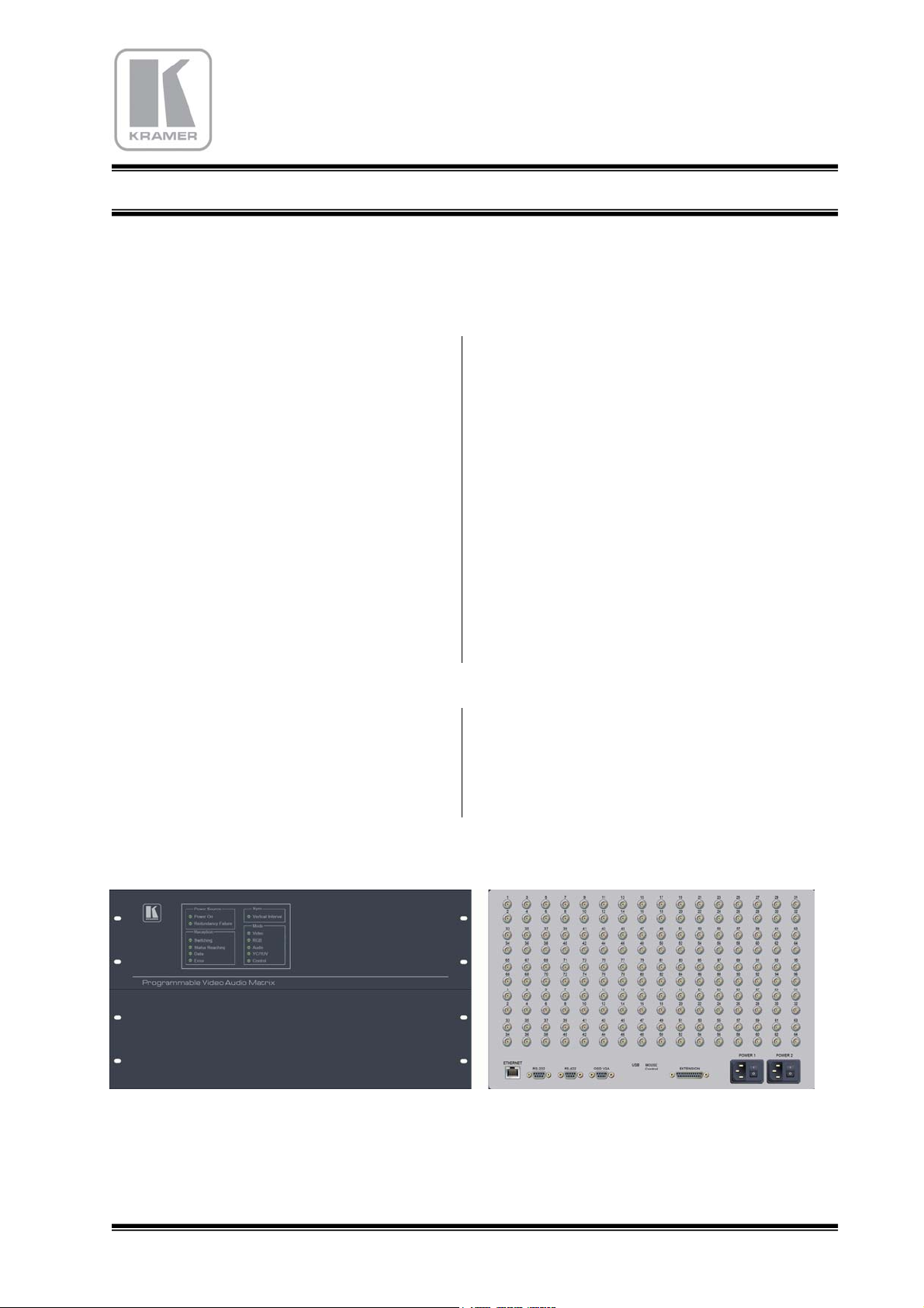
1.1 GENERALITIES
The Kramer matrix switchers are used to select and
dispatch electric signals, as audio, video and RGB,
to several destination simultaneously. The
impedances of each machine which is connected on
the matrix are well respected, even if a signal goes
to two outputs and more. As a matter of fact, a
signal under 75 Ohms can’t be delivered on several
loads without any amplification dispositive.
In fact, each output is able to select one, and only
one, input. We can consider the matrix routing
switcher as an assembly of several selectors which
are adjacent and connected on common inputs.
Each selector is fully independent, and individually
controlled. When two selectors, or more, request
the same source, this last is then distributed. So, it
have to be buffered to avoid losses of electric level
and reduce of bandwidth. The number of selectors
depends of the power and the quality of the buffers.
The control of the switching and the others
commands is provided by an interface RS232/422,
via an internal bus.
The routing switcher don’t make use of a keyboard
in front panel. The access of this keyboard should
not be easy, or impossible, when the matrix is at the
heart of the audio and video lines, to have the
shortest length.
A supervisor, a computer or a remote control panel
must necessarily control the matrix by the RS232
and RS422 connectors.
Several LED lights on the front panel shows the
receipt of the RS232/422 datas, the kind and the
result of the actions.
An electric power supply provides four various
tensions the cards of the machine.
1.2 RACK DISPOSITION
The cards are housed in a 19 inches rack, with 360
mm depth, and a height which is multiple of 3RU,
according to the number and the dimensions of
each section.
Many section, as audio, video, RGB, YC, or YUV,
can be inserted in the same rack.
The cards are introduced by the rear panel and
support the audio and video plugs.
These are BNC for composite video, components,
YC and RGB. For the audio, (balanced or
unbalanced), the plugs are terminal blocks 6 points
detachable.
2
Page 3
KRAMER
Electronics
MATRIX ROUTING SWITCHER
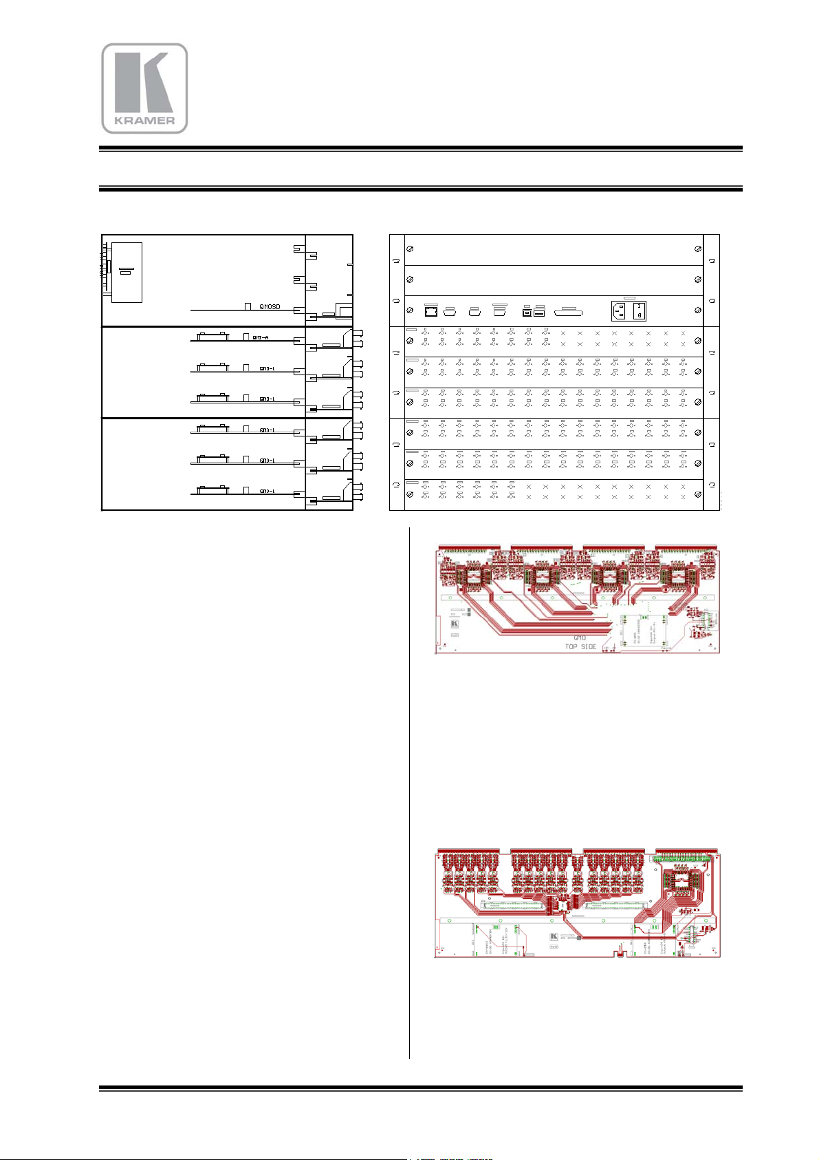
1.3 CREATING A MATRIX
The rear panel of the rack is 19” wide, on 3RU
high. The mains, RS232 and RS422 plugs 1RU,
and the useful area for the audio, video et RGB is
also 1RU. The BNC or audio connectors are shared
by 32, on horizontal bands which are 1RU wide.
We can house up to 3 bands in a 3RU area, i.e. 96
BNC or audio plugs. So, we can realize a 32x64
video matrix, or a 64x32…
When more, the rack has to be 6RU high. Then the
total number of plugs rise to 192, and permits
important dimensions. With a 9 RU rack, the
number is 288, etc.
The stereo audio plugs are also shared by 32, on
1RU band. We can house 3 bands, i.e. 96 stereo
audio plugs. For example, in a 3RU unit, we can
realize a stereo balanced 32x64 or 64x32, more in a
6RU, etc.
In YC mode, the capacity the divided by two ; in
component mode, by three ; in RGBHV mode, by
five.
1.5 RGBHV SECTION
RGBhv architecture is the same as the video
section :
Each card can support the R, G, B, H or V, and is
simultaneously controlled.
The input and output impedances is a 75 Ohms on
BNC, and the bandwidth is 350 MHz minimum.
1.6 AUDIO SECTION
The architecture of the audio path is different.
1.4 VIDEO SECTION
The video section in an area with cards including
the input and outputs plugs, the buffers, the
switchers, the outputs 75 Ohms amplifiers, and the
controllers. The input cards (called QMI), and the
output cards (called QMO), own four edge
connectors to get the power supply and the service
signals by the internal rail.
Each cards has 32 BNC connectors for in or out.
There is no module as for the video, but traditional
cards, directly connected on the internal bus. On
this bus transit the stereo audio signals, and also the
power distribution and the service signals.
3
Page 4
KRAMER
Electronics
MATRIX ROUTING SWITCHER
The cards are horizontally located, and can be
extracted by the front panel. Each card own up to
32 stereo plugs. There is two types of audio cards :
- Input audio cards.
Called WMI, these cards are identical between
themselves. The only differences are the serigraphy
of the panel and its position in the slots.
When viewing from the rear panel, these cards are
immediately slotted near the QMOSD card
(communication card). Their 32 audio plugs can be
set up in factory, as balanced or unbalanced, or
mixed.
Balanced mode has a +4dB level under 6 KOhms
impedance., and the unbalanced mode, -6dB under
10 KOhms. Dynamic is 12 dB. The inputs are
directly introduced into the integrated circuits, and
have no galvanic isolation.
- Output audio cards.
Called WMO, these cards are physically identical
between themselves, but have to be programmed
for identification. Their position is immediately
near the input cards. Their 32 audio plugs have no
galvanic isolation. The output impedance is 50
Ohms. We can use the output in balanced mode, as
in unbalanced only without connecting the inverted
pin. (Do not connect this pin to the ground).
Up to 32 VCA (Voltage Control Amplifiers) can be
wired in factory. So the audio level can be adjusted
with a special RS 232 command.
1.7 OTHERS SECTIONS
YC (S-video), component YUV, and RGsB can be
realized with the analogue video cards, with the
same principle as RGBhv section.
1.8 COMMUNICATION
The card called QMOSD is the heart of the
KRAMER matrix routing switcher. This card own
a clock generator, a microcontroller, and provides
the service signal to the others cards of the
machine. The reception and the treatment of the
RS232, RS422 and Ethernet is made inside and the
datas are then transferred the concerned switchers.
As there is no keyboard on the front panel of the
matrix, the QMOSD card take on the dialog with
the external keyboard by the RS422 link.
1.9 ON SCREEN DISPLAY
The GMOSD card has a SVGA 800x600 generator
that is available on a SubD-HD15 connector. An
external screen can be connected on, and propose a
listing of the matrix status.
On the left is shown the list of 80 input sources, as
13 characters names.
On the right area are shown 80 outputs name, with
the status of switch.
A mouse can be connected on a USB-A connector,
to control the upper tool bar, and to create switches.
The loading of this table is automatically done with
the MatrixOp4 software, after entering the
assignment operation.
1.10 INTERVAL SWITCHING
Switching during the black interval is basic to get a
clean change of picture, without break of the
synchronization, and cut in the middle of the
screens. When the reference signal is present
(blackburst), the switching takes place in the
beginning of the video frame, that is to say in the
middle of the line N°2 or 314 in PAL/SECAM
(N°2 or 264 in NTSC). The maximum waiting time
is of 20 mS in PAL and 16,7 mS in NTSC. This
operation can be effective only when the sources
are synchronized with the blackburst. If this
condition is not perform, then the switch is made
normally out of the interval time.
4
Page 5
KRAMER
Electronics
MATRIX ROUTING SWITCHER
2 COMMUNICATION
2.1 FORMAT
Interface
RS232 9600 8 no Min. :1 Max. : 5 Min. :+/-4v Max. :+/-12v +/-10v
RS422 9600 8 no Min. :1 Max. : 5 Min. :0v Max. :+5v 0v / +4v
KEYBOARD 9600 8 no Min. :1 Max. : 5 Min. :0v Max. :+5v 0v / +4v
Octet Octet 2 Octet 3 Octet 4 Octet 5
1 2 3 4
Speed
(Bauds)
FORMAT OF
THE DATA
NOTES: Input / Data : Hexadecimal number of source (00h to EFh)
Output / Address : Hexadecimal number of destination (00h to EFh)
DAT
(Bits)
Instruction Input / Data Output / Address Layer
Parity STOP
A
RxD level TxD level
(bits)
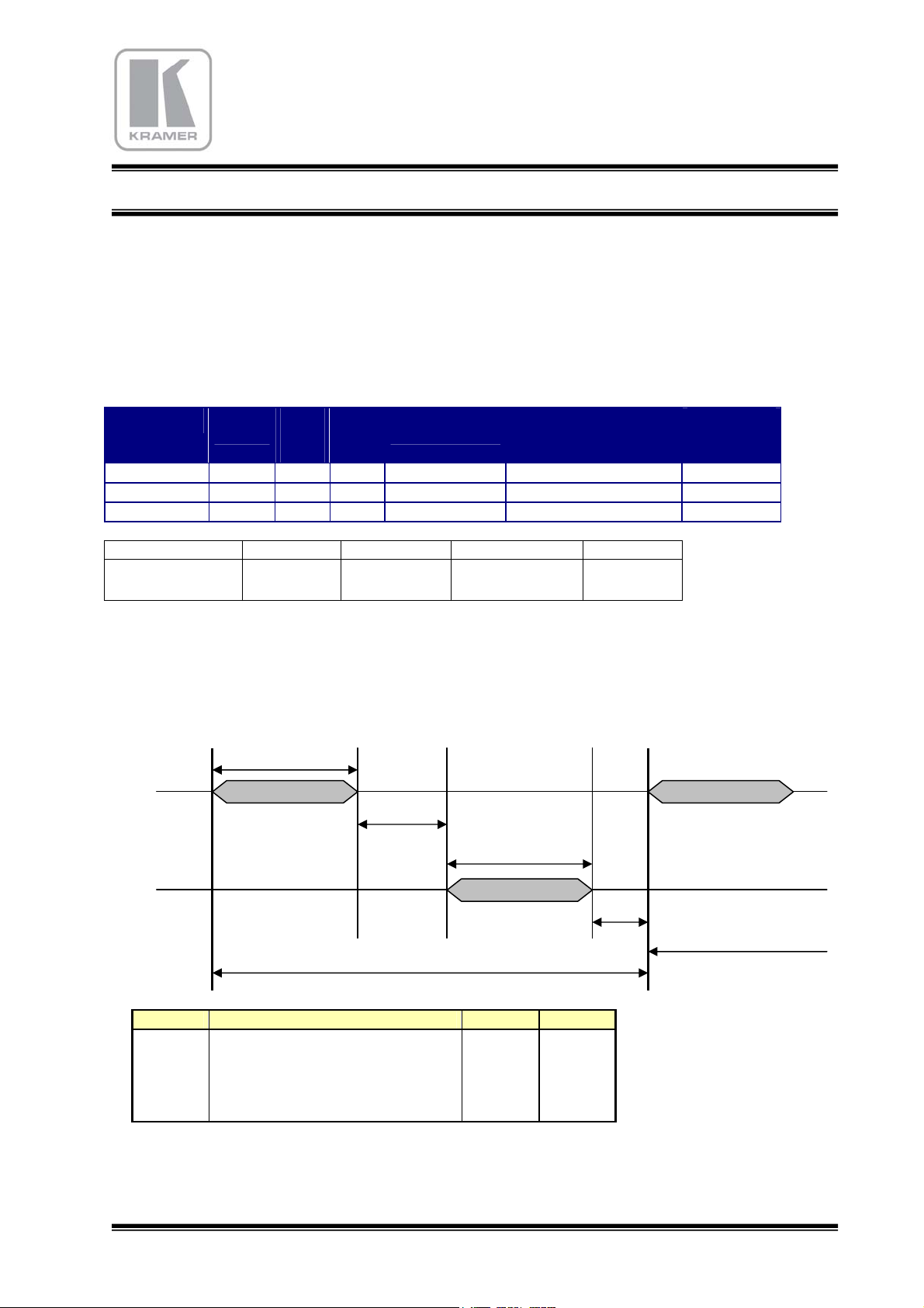
2.2 TRANSMISSION CYCLE
RX
Command from
the computer
TX
(matrix return)
Symbol Description Time Units
Trec Command reception 4 mS
Twr Working time of the Matrix 15 mS
Tret Return Informations from the Matrix 4 mS
Ts Time for ready 2 mS
Tmc Maximum time of a cycle 25 mS
EXPLANATION : Reception time RX is 4 milli-Seconds. The routing switcher operates during 15 mS, returns
the answer TX (4 mS), and comes back to ready state after 2 mS. The routing switcher takes 25 milli-Seconds to
execute a command. When a new command occurs during unready time (Tmc), this command will be
Trec
Twr
Tmc
Tret
Ts
Next command
5
Page 6
KRAMER
Electronics
MATRIX ROUTING SWITCHER
temporally stored in a stack FIFO (first-in first-out) with 2 levels records. To be sure not to overflow the stack,
the minimum time of 25 mS between each command should be respected.
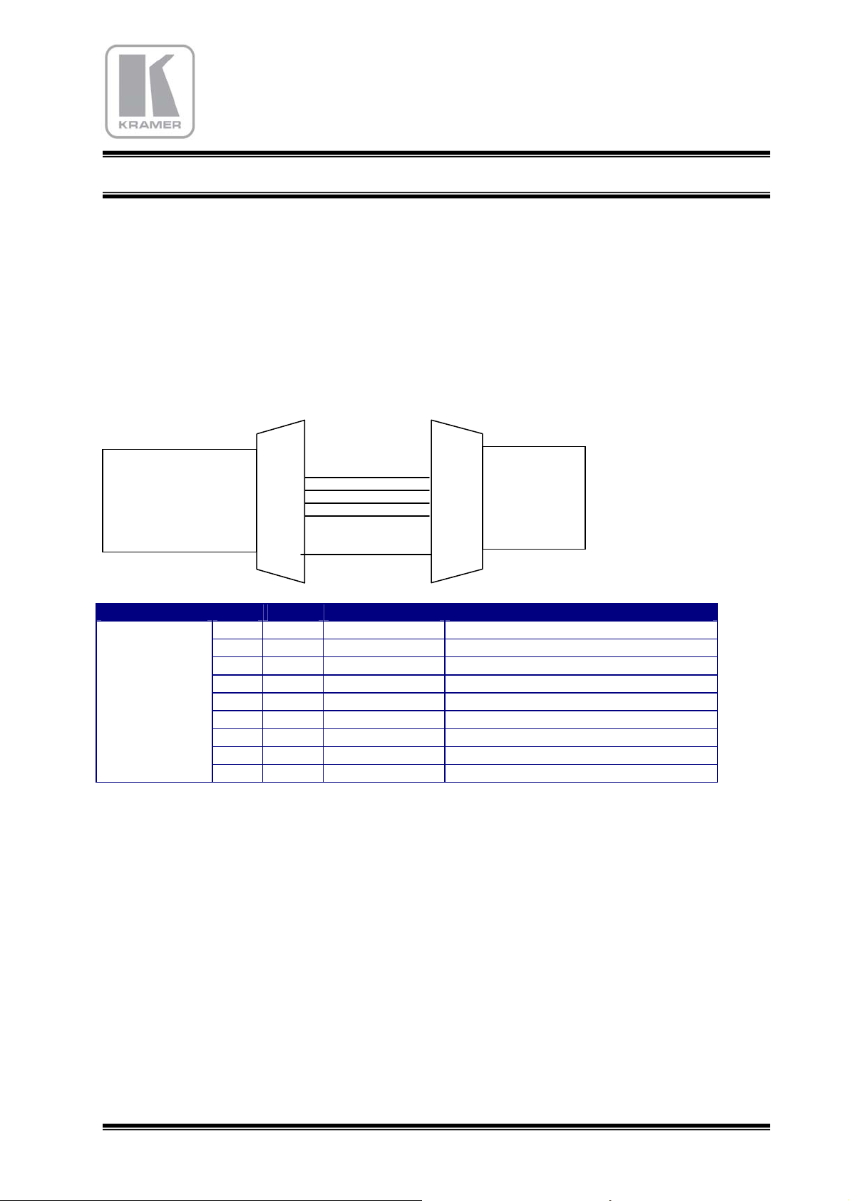
2.3 SUB-D9 CONNECTOR for RS232, RS422, and Remote Control Panels
2.3.1 RS232 Réception
The serial RS232 communication port of the matrix is a SUB-D9 female plug.
To connect a computer, you have to use a male/female uncrossed cable :
RS232
FEMALE
PLUG
MATRIX
ROUTING
SWITCHER
RS232
nc : 1
6 : nc
2
7
3
8
nc : 4
9 : nc
5
nc : 1
6 : nc
7
8
nc : 4
9 : nc
PC
2
3
5
COM
RS232
Pin Signal Direction Function
1
2 TxD
3 RxD
4
n.c. Should not be connected
Æ
Å
Transmission of the data toward PC
Receipt of the data of the PC
n.c. Should not be connected
5 GND --- Ground
6
7 CTS
8 RTS
9
n.c. Should not be connected
Å
Æ
PC ready to give out (Clear To Send)
Matrix demand to send (Request To Send)
n.c. Should not be connected
6
Page 7
KRAMER
Electronics
MATRIX ROUTING SWITCHER
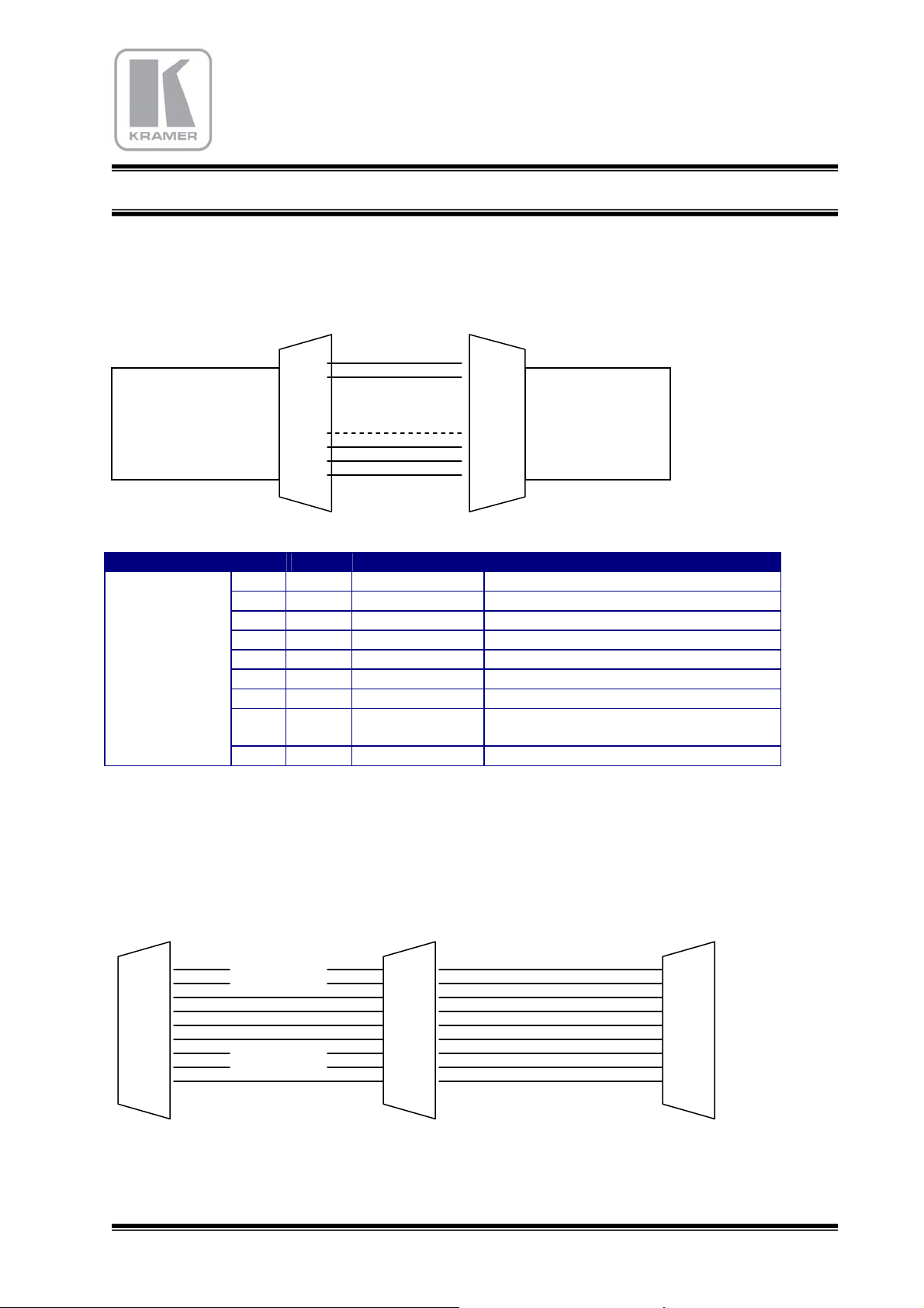
2.3.2 RS422 Reception and Remote Control Panels
The serial RS232 communication port of the matrix is a SUB-D9 female plug. To connect a RS422 device, you
have to use a male/female uncrossed cable :
MATRIX
ROUTING
SWITCHER
RS422
1
6
nc : 2
7 : nc
nc : 3
8 :
10v
4
9 : nc
6
nc : 2
7 : nc
nc : 3
8 : 10v
9 : nc
1
RS422
External
Device
4
5
Pin Signal Direction Function
Æ
Transmission of the data toward PC (diff-)
n.c. Should not be connected
n.c. Should not be connected
Å
Æ
Receipt of the data of the PC (diff+)
Transmission of the data toward PC (diff+)
n.c. Should not be connected
RS422
FEMALE
PLUG
1 Tx2
3
4 Rx+
5 GND --- Ground
6 Tx+
7
8 ALIM
Æ (+10v, 100mA) Control Panel Electric Power
Should not be connected for RS422
9 Rx-
Å
Receipt of the data of the PC (diff-)
2.3.3 RS232 / Remote Control Panel external cable separator.
This cable is realized with one 9 wires flat cable, one female SubD9, two males SubD9.
For RS232 section, wires 1, 6, 4, 9 must be cut.
to RS232 (computer) to Matrix to Remote Control Panel
SubD Female SubD Male SubD Male
1
6
2
7
3
8
4
9
5
1
6
2
7
3
8
4
9
5
1
6
2
7
3
8
4
9
5
7
Page 8

KRAMER
Electronics
MATRIX ROUTING SWITCHER
2.4 COMMUNICATION PROTOCOL 2000 TM
INCLUDING OPTIONS (02/09/2005 VER-5.06)
This RS-232 / RS-485 communication protocol uses four bytes of information as defined
below.
For RS-232, a null-modem connection between the machine and controller is used. The
default data rate is 9600 baud, with no parity, 8 data bits and 1 stop bit.
MSB LSB
st
1
byte DEST INSTRUCTION
0 D N5 N4 N3 N2 N1 N0
7 6 5 4 3 2 1 0
nd
2
byte INPUT / DATA_1
1 D6 D5 D4 D3 D2 D1 D0
7 6 5 4 3 2 1 0
rd
3
byte OUTPUT / ADRESS / DATA_2
1 A6 A5 A4 A3 A2 A1 A0
7 6 5 4 3 2 1 0
th
4
byte
1
7 6 5 4 3 2 1 0
st
1
BYTE: Bit 7 – Defined as 0.
The function that is to be performed by the switcher(s) is defined by the INSTRUCTION (6
bits). The instruction codes are defined according to the table below (INSTRUCTION NO. is
the value to be set for N5…N0).
output Bit 7 input
Bit 7
D – “DEST”: 0 - for sending to the switcher (from the PC or keyboard).
1 - for sending to the PC or keyboard (from the switcher).
N5…N0 – “INSTRUCTION”
LAYER NUMBER
L4 /
Bit 8 output
L3 /
Bit 8 input
L2 L1 L0
8
Page 9

KRAMER
Electronics
MATRIX ROUTING SWITCHER
2nd BYTE: Bit 7 – Defined as 1.
D6…D0 – “INPUT or DATA”.
When switching (ie. instruction codes 1 and 2), the INPUT (MSB + 7 bits) is set as the input
number which is to be switched. For other operations, these bits are defined according to the
table.
rd
3
BYTE: Bit 7 – Defined as 1.
A6…A0 – “OUTPUT or ADRESS”.
When switching (ie. instruction codes 1 and 2), the OUTPUT (7 bits) is set as the output
number which is to be switched. For other operations, these bits are defined according to the
table.
th
4
BYTE: Bit 7 – Defined as 1.
Bit 6 – Most Significant Bit (Bit A7) of the output byte.
Bit 5 – Most Significant Bit (Bit D7) of the input byte.
L4…L0 – LAYER NUMBER.
Used to address layers in a system via their layer numbers.
audio, YC, YUV, RGBHV) are controlled from a single serial port in a same machine, they
are usually configured separately having an individual layer number.
TABLE OF INSTRUCTION CODES FOR PROTOCOL 2000TM
Notes
: All values in the table are decimal, unless otherwise stated as Hexadecimal (xxh).
INSTRUCTION
SEND
ex
01h 1 41h 65
02h 2 42h 66
05h 5 45h 69
06h 6 46h 70
10h 16 50h 80 ERROR / BUSY 80h
11h 17 51h 81 RESERVED - - - - - - - -
15h 21 55h 85 SET AUDIO Output VCA
REPLY
Dec Hex Dec
DESCRIPTION
SWITCH
REQUEST
STATUS OF
AN
OUTPUT
VIDEO
Y / C
YUV
RGBHV
AUDIO
VIDEO
Y / C
YUV
RGBHV
AUDIO
DEFINITION FOR SPECIFIC INSTRUCTION
INPUT / DATA_1
Set equal to video input
number (+ 80h) which is to be
switched
(80h = disconnect)
80h
Equal to output number (+
80h) whose VCA is to be set
When several layers (video,
Layer Note
OUTPUT / ADRESS /
DATA_2
Equal to output number
(+ 80h) which is to be switched
Equal to output number
(+ 80h) whose status is
requested
80 - Error
81 - Invalid Instruction
82 - Out of range
83 - Machine busy
84 - No card
85 - Address out of range
86 - Data out of range
87 - Machine busy
Set as VCA value (32 steps) :
Dec : 128 to 159
Hex : 80h to 9Fh
Hex
81h 1
82h 1
83h 1
85h 1
81h 1
81h 2
82h 1
83h 1
85h 1
81h 2
81h 3
81h
81h 1,4
9
Page 10

KRAMER
Electronics
MATRIX ROUTING SWITCHER
SET AUDIO GAIN for
audio input
16h 22 56h 86
19h 25 55h 85
19h 25 56h 86
20h 32 60h 96
21h 33 61h 97 LINE 80h
22h 34 62h 98
23h 35 63h 99
39h 57 79h 121 RESERVED - - - - - - - -
39h 57 79h 121
3Dh 61 7Dh 125 IDENTIFY MACHINE
SET AUDIO Balanced or
Unbalanced mode
for audio input
REQUEST Audio
output VCA
REQUEST Audio
input GAIN / Unbal/Bal
SET ADR TEXT (wp=1) High Byte (+ 80h) Low Byte (+ 80h)
SET DISPLAY TEXT 80h Text ASCII (+ 80h)
CLOSE TEXT (wp=0) High Byte (+ 80h) Low Byte (+ 80h)
Keyboard touches Touch number (+ 80h) TDC current dest touch + 80h
Keyboard lights
Keyboard lights Dest LED number for DEST (+ 80h) TDC current dest touch + 80h
Keyboard lights Blink Blinked LED number (+ 80h) TDC current dest touch + 80h
Keyboard LCD Text start Source Touch number (+ 80h) Char 1 (+ 80h)
Keyboard LCD Text start
with star switcher
Keyboard LCD Text Char 1 (+ 80h) Char 2 (+ 80h)
Keyboard LCD Text Dest Touch number (+ 80h) Char 1 (+ 80h)
Keyboard LCD Text with
LCD display
Keyboard LCD info
Keyboard Inputs (1..8)
Restriction video start
(one shot)
Keyboard Inputs
Restriction video
(sequence 15 shots)
Keyboard Inputs (1..8)
Restriction audio start
(one shot)
Keyboard Inputs
Restriction audio
(sequence 15 shots)
SET Serial Number High Byte Low Byte
Mode Test 2 2
SET License
OSD VGA screen 80h
SET Power On Reset 80h VCA + Slope (+ 80h)
Equal to input number (+ 80h)
whose gain is to be set
Equal to input number (+ 80h)
whose gain or bal/unbal mode
is to be set
Equal to output number (+
80h) whose gain is requested
Equal to input or output
number (+ 80h) whose gain is
requested
LED number (+ 80h)
(80h=all lights off)
Source Touch number (+ 80h) Char 1 (+ 80h)
Char 1 (+ 80h) Char 2 (+ 80h)
81h : no input key
82h : disconnected
84h : no dest. Key
88h : no dest card
90h : no source
Byte : (8,7,6,5,4,3,2,1)
0 = normal
1 = restricted
Byte : (8,7,6,5,4,3,2,1)
0 = normal
1 = restricted
Byte : (8,7,6,5,4,3,2,1)
0 = normal
1 = restricted
Byte : (8,7,6,5,4,3,2,1)
0 = normal
1 = restricted
80h – Internal Statements
reading
Gain value 32 steps:
“100ggggg”
ggggg = 0 to 31 (0 to 1Fh)
- Bal mode : 160 (A0h)
(10100000bin)
- Unbal mode : 224 (E0h)
(11100000bin)
80h
81h
80 - OFF LINE
81 - ON LINE
TDC current dest touch+ 80h
80h
Equal to output number
(+ 80h) which inputs have to
be restricted
Equal to output number
(+ 80h) which inputs have to
be restricted
Equal to output number
(+ 80h) which inputs have to
be restricted
Equal to output number
(+ 80h) which inputs have to
be restricted
0- no license
license active
1-
80 - Refresh
81 - OSD active flip-flop
80 - Serial Number
81 - Power On Reset
82 - OSD status
83 - Reserved LIC
0-
no license
license active
1-
81h 1,5
81h 1,5
81h 2,6
81h 2,6
90h
91h
92h
81h 9
81h
82h
83h
84h
90h
91h
92h
93h
94h
95h
96h
97h
98h
99h
81h
82h
83h
01h
82h 11
83h 10
81h 8
10
Page 11

KRAMER
Electronics
MATRIX ROUTING SWITCHER
NOTES on the above table:
NOTE 1 - These are bi-directional definitions. That is, if the switcher receives the code, it will perform
the instruction; and if the instruction is performed (due to a keystroke operation on the front panel),
then these codes are sent. For example, if the HEX code
01h 85h 88h 83h
was sent from the PC, then the switcher (Layer 3 = YUV) will switch input 5 to output 8. If the user
switched input 1 to output 7 via the front panel keypad, then the switcher will send:
41h 81h 87h 83h
to the PC.
When the PC sends one of the commands in this group to the switcher, then, if the instruction is valid,
the switcher replies by sending to the PC the same four bytes that it was sent (except for the first byte,
where the DESTINATION bit is set high).
NOTE 2 - The reply to a "REQUEST" instruction is as follows: the same instruction and INPUT codes
as were sent are returned, and the OUTPUT is assigned the value of the requested parameter. The
replies to instructions 10 and 11 are as per the definitions in instructions 7 and 8 respectively. For
example, if the present status of machine layer 5 (RGBhv) is breakaway setting, then the reply to the
HEX code
0Bh 80h 80h 85h
would be
4Bh 80h 81h 85h
NOTE 3 - An error code is returned to the PC if an invalid instruction code was sent to the switcher, or
if a parameter associated with the instruction is out of range (e.g. trying to switch a 16x16 matrix with
an input or output greater than 16, or trying to switch an input or output greater than the highest one
defined). This code is also returned to the PC if an RS-232 instruction is sent while the machine is
being programmed via the front panel. Reception of this code by the switcher is not valid.
NOTE 4 – The output VCAs are 32 logarithmic steps. Values are 0 to 31 (decimal).
NOTE 5 – The input levels are 32 logarithmic steps. Values are 0 to 31 (decimal) and coded in the 5
lowest bits of the output byte.
When bit 5 = 0, the gain value is taken.
When bit 5 = 1, the Balanced/Unbalanced mode is taken : bit 6 = 0 for Balanced mode, bit 6 = 1 for
Unbalanced mode.
The reply always contains the Balanced/Unbalanced mode and the Gain value under the binar form :
1 bal/unbal 1 G4 G3 G2 G1 G0
Where bal=0 and unbal=1
the reply to the HEX code
16h 82h 85h 81h
would be (for a balanced mode)
56h 82h A1h 81h
NOTE 6 – The Output VCAs are 32 logarithmic steps. Values (0 to 31 decimal) are replied in the
output byte.
The input levels are 32 logarithmic steps. Values are 0 to 31 (decimal) and coded in the 5 lowest bits
of the output byte.
The reply always contains the Balanced/Unbalanced mode and the gain value under the binar form :
11
Page 12

KRAMER
Electronics
MATRIX ROUTING SWITCHER
1 bal/unbal 1 G4 G3 G2 G1 G0
Where bal=0 and unbal=1
the reply to the HEX code
19h 82h 80h 81h
would be (for a maximum VCA)
55h 82h 9Fh 81h
NOTE 7 – This code is reserved for internal use.
NOTE 8 - The serial number is replied as BCD code, with Most Significant Byte in the input byte and
Less Significant Byte in the output byte.
NOTE 9 – When OFF LINE mode, sending a switch instruction will store the data in the volatile matrix
memory, without effective switch. Switch will be done when ON LINE instruction.
When ON LINE mode, sending a switch instruction will execute normal switch.
NOTE 10 – POWER ON RESET. The output register has a value under the binar form :
1 0 POR1 POR0 P3 P2 P1 P0
P3…P0 : vca slope from 0 to 9 seconds
POR1 = 0 :
POR0 = 0 : vca max when power on.
POR0 = 1 : vca min when power on.
POR1 = 1 : recall vca when power on.
NOTE 11 – REFRESH the ON SCEEN DISPLAY. The GMOSD card will be restarted to be refreshed.
12
Page 13

KRAMER
Electronics
MATRIX ROUTING SWITCHER
3 MATRIX HOOK-UP
3.1 MAINS AND GROUND ISOLATION
The electric ground of all the plugs are the same, but isolated from the rack.
The rack is directly grounded by the mains cable.
3.2 VIDEO
Video inputs and outputs are standards plugs BNC 75 Ohms.
BNC BNC
Electric equivalent plan :
3.3 RGBhv
RGBHV inputs and outputs are standard plugs : BNC.
R,G, and B signals are analogue under 75 Ohms. Level = 1V
H and V are digital under 1 KOhms. Level = 2V to 5V
BNC BNC
13
Page 14

KRAMER
Electronics
MATRIX ROUTING SWITCHER
3.4 AUDIO
Audio inputs and outputs are terminal blocks 3 points detachable:
3.4.1 BALANCED INPUTS
XLR :
Ground
Hot Point
Cold Point
1- Ground
Hot
23- Cold
3.4.2 UNBALANCED INPUTS
RCA :
Ground
Signal –10dB
1- Ground
2-
Hot
3- nc
3.4.3 BALANCED OUTPUTS
XLR :
1- Ground
Hot
23- Cold
Ground
Hot Point
Cold Point
3.4.4 UNBALANCED OUTPUTS
RCA :
1- Ground
Hot
23- Cold
Important Note:
DO NOT CONNECT SKEWER 3 TO THE
GROUND
(audio signal always present on this line).
Ground
Signal –10dB
Note :
skewer 3 no connected. Do not connect to the
ground.
14
Page 15

KRAMER
Electronics
MATRIX ROUTING SWITCHER
4 GENERAL FEATURES
4.1 VIDEO SECTION
- Bandwidth @ -3dB: 350 MHz
- Crosstalk @ 4,43 MHz:
-50 dB between two adjacent lines.
-55 dB between two extreme lines.
- Differential gain : 0,15% max.
- Differential phase : 0,1° max.
- Signal/Noise Ratio > 60 dB @ 4.43MHz
- Delay signal input/output matrix: 35 nS
- Chrominance/luminance delay < 10 nS
- Clamp on bottom of synchronization: -0,3V
- BNC connectors 75
- Switching Point Assignment down by PROM
programming
4.2 Analog AUDIO SECTION
- Bandwidth @ -6 dB: 20 KHz
- Crosstalk @ 1 KHz:
-70 dB between two adjacent lines.
- Harmonic distortion < 0,05%
- Signal/Noise Ratio > 70 dB
- Terminal blocks 3 points detachable:
skewer 1: shield, mass, earth
skewer 2: hot point or asymmetric signal
skewer 3: cold in balanced, or non connected
point in unbalanced
4.3 DIGITAL AUDIO AES/EBU
- Bandwidth @ -3dB: 50 MHz
- Jitter max: 20nS
- Numeric Rise Time gap: 30 nS
- Crosstalk @ 5,12 MHz: -60 dB
Standard AES 3
- Impedance: 110 balanced
- Min/Max Input Level: 1V/5Vp-p (110 loaded)
- Output Level: 5Vp-p (110 loaded)
- Connector type : detachable terminal blocks 3pts:
skewer 1: shield, mass, earth
skewer 2: signal
skewer 3: reversed signal
Standard AES 3-id
- Impedance: 75 unbalanced
- Input Level: 1Vp-p (75 loaded)
- Output Level: 1Vp-p (75 loaded)
- Connector type : BNC
4.4 COMMUNICATION SECTION
- Rate: 9600 Bauds, 8 bits, without parity, 1 start
bit, 1,5 stop bit
Sub-D9 RS232S connector (measures in relation to
the mass 0V) :
- levels: max: +/-12V min: +/-4V
- tension of rest: - 10V
- tension work (start bit): +10V
- Start 1 bit time: 104 µS
Sub-D9 RS422S connector (measures in relation to
the mass 0V) :
- level in rest Txd+ : +4,5V
- level in rest Txd- : 0,5V
- level in rest Rxd+ : +4,5V
- level in rest Txd- : 0,5V
4.5 MAINTENANCE
DISASSEMBLY OF THE COMMUNICATION,
VIDEO AND AUDIO CARDS.
Power off the matrix.
For the removal of the active cards and Power
Supplies, undo the tightening screws on the edge of
the panel and pull on the card, power off.
For removal of the Power Supply block, withdraw
the adjacent panel to facilitate access.
Then disconnect the power cord and exchange the
Power Supply block.
For the extraction of the communication / audio /
video connectors cards (see diagram of
implantation of the matrix in beginning of this
manual), it is necessary to withdraw all cables that
are fitted to the same block.
The cards must be returned to the factory for testing
purposes. A visual examination can be made by the
user for the audio and video connectors.
15
Page 16

KRAMER
Electronics
MATRIX ROUTING SWITCHER
5 TOUCH KEYBOARD : LUMINOUS RE-LABELABLE
5.1 PRESENTATION
The keyboard permits the remote control of the switching matrix, without the use of a PC station.
It is housed in 19" 1‘U’cabinet, with 8, 16, 24 or 32 selection, or in a built-in box. The selected key is
illuminated. Each of the keys can be re-labelled, by writing in the name of the source or the destination.
This keyboard is auto - powered by the matrix, via the RS422 connector. Several keyboards can connect in
parallel on the RS422 line.
Parameters are given in the MatrixOp4 software
5.2 HOOK-UP
Connect the keyboard to the
switching matrix by a straight
flat cable and complete with
Male/Female Sub-D 9
connector, in the
RS422/keyboard connector of
the matrix, and the
RS422/matrix connector of
the keyboard. The set of the
keys blink when power is on.
5.3 EDITING PARAMETERS
Each key can get an individual function as Source
call, Destination call, or level audio +/-.
(see page 20 Control panel Programming)
5.4 WORKING
First select an output (destination) using the keys of
the right part of the keyboard. The key illuminates,
as does the key that corresponds to the activated
input of the matrix. This operation does not activate
any switching, but allows you to show the status of
the matrix.
Choose an input (source) on the left part of the
keyboard. The key of the input illuminates if the
switching is OK.
The matrix also acknowledges receipt of the
switching by writing on the LCD display in the
front panel: « Comm/destination/source».
5.5 SCHEMATIC
This schematic is representative of the affectation of the keys. Each key can get a special function which can be
input or output, and video and/or RGB and/or audio.
The affectations are installed in the procedure « MENU EDITOR » of the MatrixOp4 software (see page 20
Control panel Programming), and down loaded to the EEPROM memory of the switcher.
1 2 3 4 5 6 7 8 9 10 11 12 13 14 15 16
17 18 19 20
21 22 23 24
25 26 27 28
29 30 31 32
16
Page 17

KRAMER
Electronics
MATRIX ROUTING SWITCHER
6 INCREMENTAL TOUCH KEYBOARD AND LCD DISPLAY
6.1 PRESENTATION
This keyboard permits the remote control of the
switching matrix, without the use of a PC station.
It is housed in a 19 inch 1U cabinet, with 2 keys for
selection of the inputs, 2 keys of selection for the
outputs, and a validation key. The configuration
status of the switch actions selected is shown on the
LCD display.
This keyboard is powered from the matrix, via the
RS422 connector.
Several keyboards can connect in parallel on the
RS422 line, and are interactive.
6.2 HOOKUP
Connect the keyboard to the Matrix by a straight
flat cable and complete with Male/Female Sub-D 9
connector, in the RS422/keyboard connector of the
matrix, and the RS422/matrix connector to the
keyboard.
6.3 EDITING PARAMETERS
Parameters are given in the MatrixOp4 software
(see page 20 Control panel Programming)
6.4 WORKING
First select an output (destination) using the two
keys destination + and -. The LCD display indicates
the selected destination ( output n), and also the
state of the corresponding active input. This
operation does not make a switch action, but does
permit the display of the state of switching of the
matrix.
Then choose an input (source) using the two keys
source + and -. The LCD displayer indicates the
selected source (input n). As before, this operation
does not invoke a switch action.
Validate then using the ‘validation’ key . The
keyboard then sends the switch command to the
matrix.
The display confirms the action by one asterisk *.
The matrix also acknowledges receipt of the switch
action by writing on the LCD display on the front
panel: «Comm/destination/source».
In case of receipt: «Err. /destination/source», the
communication from keyboard to matrix has not
been made correctly.
Check the RS422 cable. Also check the capacity of
the matrix in relation to the demand of the
keyboard.
6.5 SCHEMATIC
This schematic shows the front panel of the touch keyboard and LCD display.
06 source name
15 destination name
Affichage LCD Sélection
Source- Source+
Dest- Dest+
17
Valid.
Page 18

KRAMER
Electronics
MATRIX ROUTING SWITCHER
7 MatrixOp4 SOFTWARE
7.1 INTRODUCTION
The principle of the routing switcher is to connect
each of its outputs to any or all of the inputs.
Therefore the possible points of switching is a
multiple of the number of inputs and the number of
outputs.
This principle is best described in the listview form.
This grid is composed of switching points, and of
distributors. (For instance Input 1 can be switched
to Outputs 6,7 and 8…)
The management of these switching points can be
activated by using a touch keyboard, but this
solution can quickly become complex as the matrix
becomes larger. Thus the use of a computer to
manage the system is preferable.
The MatrixOp4 software does not physically
represent the routing switcher, but rather the
environment in which the various devices exist.
Therefore you will have to display these devices in
a diagram, without taking into account their state of
readiness, or receiver, video or audio (mono or
stereo), nor of their hook-up to the grid.
A simple control allows you know quickly the
actual setup of the matrix.
7.2 Glossary :
Assignment
An audiovisual device which is connected on the
switcher may be assigned : MatrixOp4 has to know
its parameters : names and numbers of the
connectors.
Destination
Object connected on an output of the switcher.
On Line / Off Line
When the router is « OFF LINE », all information
is received and stored, but not executed. Recall and
execution are made when « ON LINE ».
Object
The devices connected on the matrix routing
switcher are called in this documentation
« objects », and have to be parametered with the
assignment editor (see page 19 assignments editor).
this edition have to be realized only in the first
installation or when changing some equipment.
Page or Sheet
The status of the router, the VCA levels, and the
general information about the connections, are
called « page », are saved in files with extension
« .cnx ».
Layer
A matrix routing switcher can contain many
different layers, according to the kind of electric
signals :
Composite Video layer
Analog Audio (mono or stereo) layer
S-Video (or YC) layer
YUV layer
RGB or RGBS or RGBHV layer
AES-EBU (Digital Audio) layer
SDI (Digital Video) layer
18
Page 19

KRAMER
Electronics
MATRIX ROUTING SWITCHER
Source
Object connected on an input of the switcher.
Disconnect
A destination is disconnected when there is no link
with any source. This status is symbolized by a
fictive object that has to be assigned as a source
called « disconnected ».
7.3 STARTING
7.3.1 Power On
The software MatrixOp4 should be installed on
hard disk.
Switch Power on of the routing switcher, the PC
and the screen.
Start the system by clicking « matrixop4.exe », then
the switching program takes over and runs
automatically.
After an auto-test, the program is ready, and
positions itself on the page that has been previously
automatically protected.
It establishes the links, and transmits them to the
matrix.
The auto-test was designed to check the correct
functioning of the matrix.
7.3.1.1 SET-UP
When just installed, the software may be initialized.
The matrix may be linked. Setup request
automatically the size of the matrix.
If fault arises :
1) Check that the routing switcher is « power on »
2) Select another port
3) Check the link between PC and Matrix unit
with the RS-232 cable
4) The LED display of the routing switcher must
lit a switching to every transmission.
5) Check if there is evidence of connection
between the devices declared in the menus and
the real configurations of the matrix. Check
that there is not more numbers than the
physical capacity of the matrix.
Verify the whole matrix/PC and restart the
program.
7.3.2 STOPPING THE SYSTEM
Turn off of the power.
The switching off of power to the central unit (PC)
and its screen doesn’t alter the connection of the
matrix (as long as the matrix is powered).
Switching off power to the routing switcher will
cease all switching actions. When switching on the
matrix, it will keep its previous configuration.
MatrixOp4 can reset the matrix however with the
“initialization” command.
7.4 ASSIGNMENTS EDITOR
7.4.1 COMMAND : Assignments
To run this subroutine, click the assignment
command. This program establishes the name and
the state of the peripheral objects.
This is the only moment where the numbering of
the audio and video connectors is shown.
When opening of this program, this window
appears, as well as a schematic representation of
the routing switcher and of the peripheral objects.
This very simplified schematic is as a real wiring
map sheet.
Four layers can work simultaneously, and each one
can have a different size.
This list form can be managed with all the function
menu, as file/edit/view/audio levels/ matrix upload.
19
Page 20

KRAMER
Electronics
MATRIX ROUTING SWITCHER
7.4.1.1 Names and Connectors capture.
Click on the line of a source or destination object.
This window opens :
This window represents the state of an object.
Enter the name of the object, or select it in the list.
Each new name will be automatically added in the
list. This is easy to get it again for other object with
the same name in another column or layer.
If an object with the same name exist in the current
column, MatrixOp4 will ask you if you want to
remove the existing one.
Choose the number of the connector of your object
in each layer. This will be useful the find easily
your objects on the connexion board.
For example, name “camera2” for video player as
source, choose video “2” if BNC N°2 is used,
choose audio “5” if audio connector 5 is used for
this camera, etc…
7.4.1.2 Remote Control Panel programming.
For both remote control panels, 32 Touches or
LCD, it is possible to assign a function for each
touch. In the case of 32 touches panel, each touch is
materially represented on the picture, respectively
from 1 to 32. A second panel can follow up to 64, a
third to 96, and so on. In the case of LCD panel,
each touch is represented as a step of
incrementation, for source and destination.
The list of the steps is also available in the
combobox “Remote panel control”.
When the name and the connectors assignment is
defined, you can choose the number of the touch,
(or the step), you want to assign on your control
panel. Selecting a touch will automatically assign it
in the opened direction (source or destination). The
touch will take the colour, blue for input, red for
output, magenta for other special functions. The
number of the touch is not necessary the same as
the layers numbers. If no touch is selected, this
object (source or destination) will not be accessible
by the remote control panel. The OK button will
valid this window datas.
The remote control panels will be operational after
an assignments upload, described below.
7.4.1.3 Assignments Upload.
When the assignments are defined, you can upload
the datas to the EEPROM of the matrix for the
remote control panel to get autonomy and be
independent of the computer. Select the menu
“Matrix / Upload EEPROM”, and follow the
procedure. The upload takes about two minutes.
The control panels should not be used while
uploading.
7.5 MATRIX CONTROLLER
7.5.1 General Informations
The mains routine of the software MatrixOp4
consist to create some crosspoints between various
sources and destinations.
MatrixOp4 don’t use the numbers of the connectors
to the devices, but only the names of these devices.
The connections are directly made between the
sources and the destinations. MatrixOp4 calculates
each crosspoint, and returns the router, the code
containing the layers and the connectors numbers.
As a matter of fact, several connections can be
done with only one operation. The video, RGB,
audio and YC layers can be following, or separated.
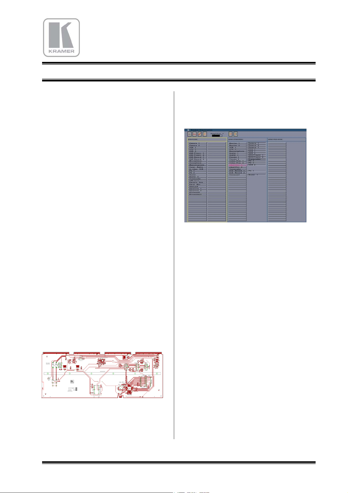
7.5.2 The Switching Display
20
Page 21

KRAMER
Electronics
MATRIX ROUTING SWITCHER
This mode of display is characterized by several
personal lines corresponding each one at a
destination, which is identified on the left side. On
the right side, the four sources that are connected
are shown, and can be changed.
7.5.2.1 Selecting and Switching
First, choose a destination by clicking on the line.
Then, a new window opens, with the list of
available sources in each layer :
In this window, choose in the separate layers list
that you want use, or in the common list, the
sources you need. The switching will be
automatically effective according the possibilities.
7.6 COPY BACK-UP
When the edition of the menu is finished, it is
important to make a copy. Save the file:
C:\Program Files\Matrixop4\*.agn
To save the switching part, the files have the
extension .cnx
Warning: the MatrixOp4 licence that you possess
works only with the delivered matrix. A copy of it
cannot work on an other matrix. The normal
working of the software MatrixOp4 may be
reduced to a minimal size and interrupted
automatically after several days of use. An
intermittent message box may open for indication.
In this case, the raising of this procedure won’t be
provided to the holder of the invoice of purchase of
the matrices and the software that after operation of
the total transfer of property, in application of the
reserve of property stipulating the complete
payment of the price. In case of contestations, the
Courthouse of Trade of Jerusalem will be alone
competent. To consult us for the adaptation and the
authorization.
7.6.1 Remark
Your PC must be equipped with a mouse as well as
the software DOS/WINDOWS 95/98/NT/XP @.
The computer should have a 256MO RAM, a
SXGA video card, and a Serial Com port.
21
 Loading...