

Page 1

User’s Manual
SIERRA VIDEO SYSTEMS
SP-14 Setup Guide
Page 2
SP-14 Setup Guide
Version 1.0
1
Page 3

Contents
Introduction 3
The Basic System 4
Flexible Connectivity 5
Control via Front Panel Buttons 6
Set Scaler Functions 7
Input resolution and Frame Rate 7
Output Resolution and Frame Rate 7
Lock Mode (Genlock Timing) 8
Aspect Ratio Mode 9
MEMC (Motion Compensation) Mode 10
MEMC Cadence 13
MEMC Mask 14
Input Adjustments 15
Input Select Button Allocation 17
Audio Channel source selection 18
2
Page 4
Introduction
This guide is a non-technical introduction to operating The SP-14 for up/down/cross standards
conversion with MEMC motion compensation.
The guide describes how to setup, scale, adjust for the best pictures.
This guide does not replace the product user manual and covers only the essential functions to get
started. For further information refer to the user manual.
3
Page 5
Setting up SP14
Connect Inputs and outputs
Set Output resolution and Frame Rate
Set Lock Mode (Genlock reference)
Set Motion Compensation modes
Set Exclusion zone
Set input characteristics
Input Adjustments and Video Filters
Input Button assignment
Audio Input Select and channel swap
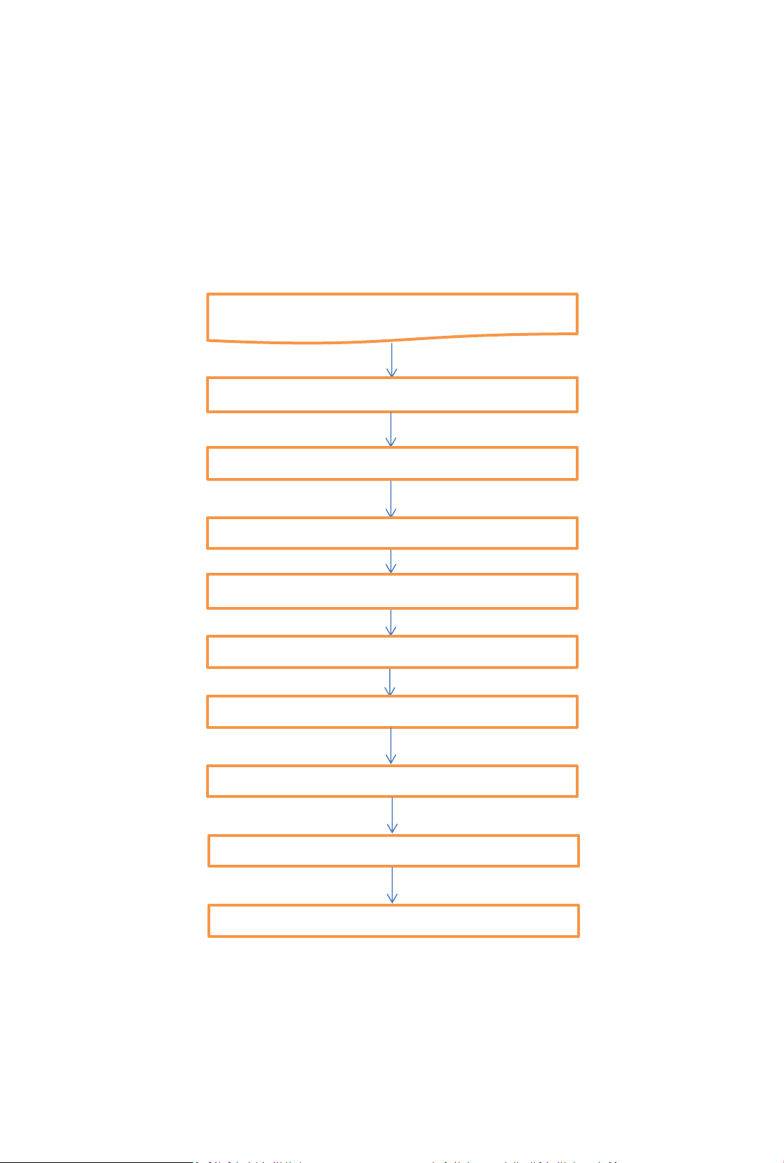
The Basic Setup
The flowchart below represents the basic setup, additional information can be found further in this
guide.
4
Page 6
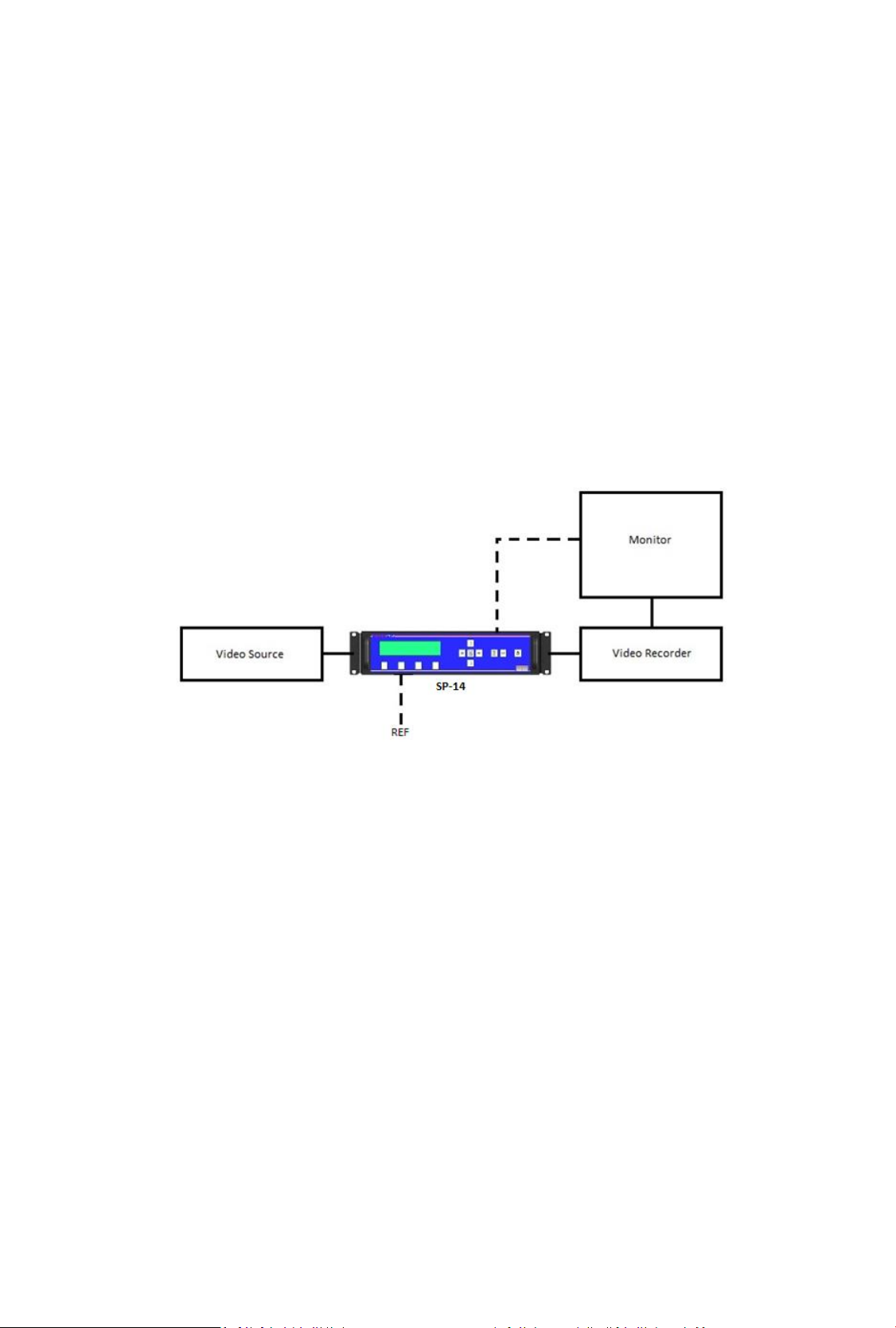
Flexible Connectivity
The SP-14 can be used as a routing switcher and universal interface for connecting many up-to-date
and legacy formats
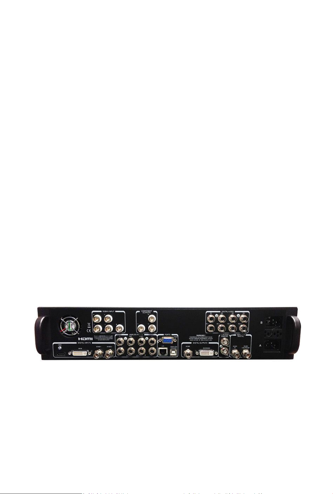
Inputs
2x 3G-SDI with automatic cable EQ, (HD-SDI & SD-SDI compatible) with embedded audio capability
for 3G, HD & SD
1x HDMI with audio & deep colour, HDCP compatible
1x DVI-D, HDCP compatible
1x VGA Analogue graphics via 5 BNCs, supports RGBHV & RGsB
2x Composite Video via BNC (NTSC/PAL/SECAM)
1x S-Video via 2x BNC (NTSC/PAL/SECAM)
1x Component video YPbPr via BNCs
4x AES 48KHz digital audio pairs via BNCs
Outputs
1x 3G-SDI (HD-SDI/SD-SDI compatible) with embedded audio for 3G, HD & SD
1x DVI-D, HDCP compatible, HDMI deep colour capable, dual-function output automatically switches
between DVI or HDMI depending on device connected to output
1x Component Analogue YPbPr
4x AES 48KHz digital audio pairs via BNCs
NB: For non-HDCP input signals all outputs can be used simultaneously but if the input signal is HDCP
encrypted then only the DVI/HDMI output is available due to HDCP licensing rules.
SP-14 Rear Panel
5
Page 7

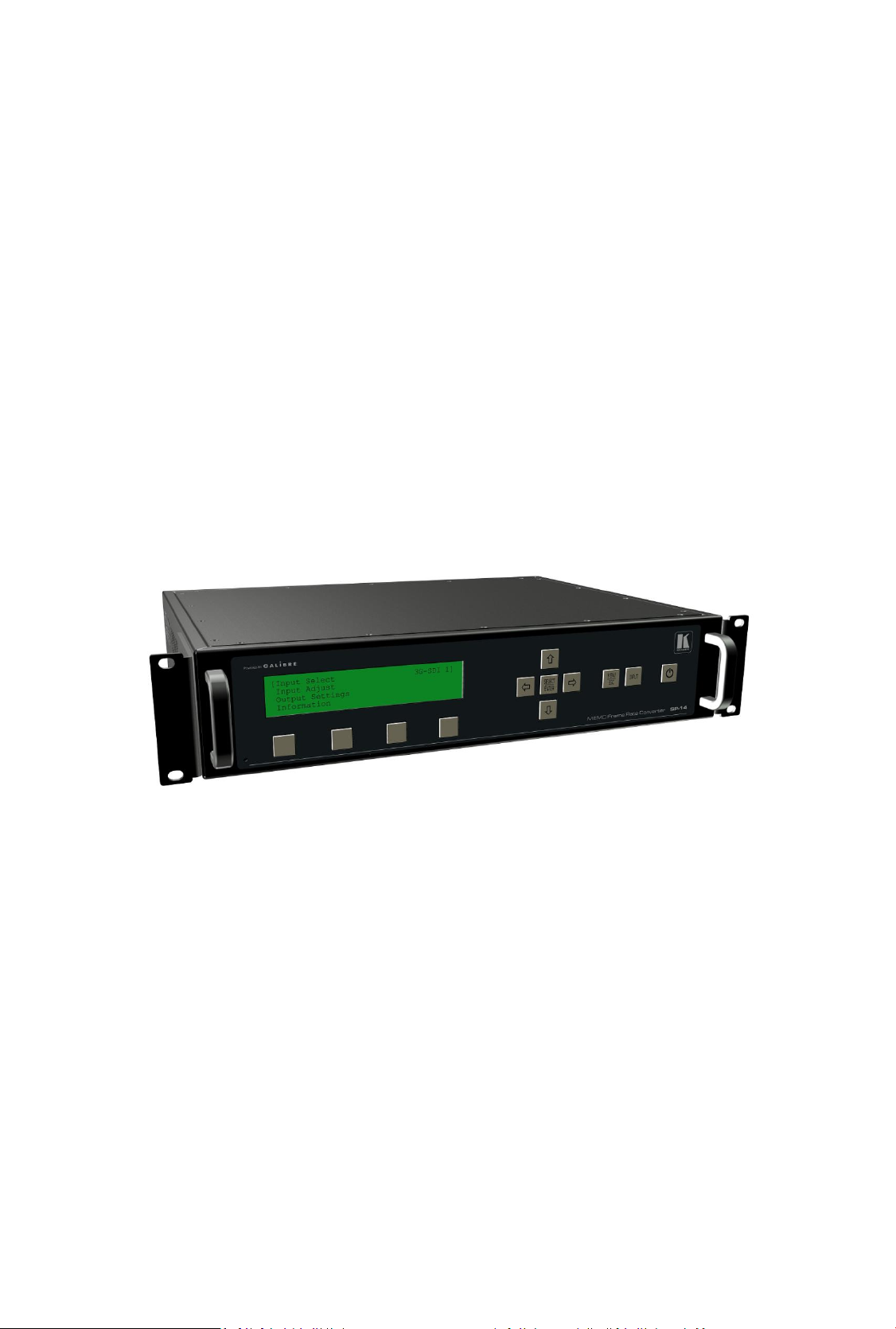
Control via Front Panel LCD and Menu Buttons
The SP-14 has front panel LCD display which gives status information and access to the in-built menu
system.
Kramer Electronics Ltd.
SP-14
Software Ver:
Safe Operation
SP-14 features safe operating conditions
1) The front panel Standby button must be pressed and held for 4 seconds to activate
2) The front panel channel select and menu buttons are locked by default; to activate the front panel
press the menu button and then the input button
IN: 1920x1080i @50.00 Hz 3G-SDI 1
OUT:1920x1080i @59.94 Hz Free Run Mode
>>> Now press’INPUT’key to unlock <<<
3G-SDI 1 C-YPbPr HDMI Test Pat
Attempting to operate menu when keypad is locked will prompt this message in the summary screen
IN: 1920x1080i @50.00 Hz 3G-SDI 1
OUT:1920x1080i @59.94 Hz Free Run Mode
Unlocked Keypad Preset 1
3G-SDI 1 C-YPbPr HDMI Test Pat
When the keypad is un-locked this message will show in the summary screen
This feature can be disabled in Menu>Miscellaneous>Unit Configuration
All menu items can be accessed via the front panel
1) Press ‘Select/Enter’ to access the menu
2) Use the ‘up & down’ keys to navigate the required menu item to the top of the screen
3) Press ‘Select/Enter’ to access that item
4) Repeat 2) and 3) to reach the item of choice
5) Use ‘left and right’ keys to select chosen mode
6) Press ‘Menu/ESC’ to back out of menu items
6
Page 8

Setting Scaler Functions
Default Settings
The SP-14 comes with default setting that should give good results on most content but you do need
to decide on some parameters for your application. As you get used to the unit you can be more
adventurous
Input resolution and frame rate
The input resolution and frame rate is recognised automatically and displayed on top line of the
status menu screen
IN: 1920x1080i @50.00 Hz 3G-SDI 1
OUT:1920x1080i @59.94 Hz Free Run Mode
Unlocked Keypad Preset 1
3G-SDI 1 C-YPbPr HDMI Test Pat
In this example the input is 1920x1080P at 50Hz from the 3G-SDI input 1
Set Processor Output Resolution and Frame Rate
Set the processor output resolution and frame rate you require in the Output Settings menu
Using the up and down arrow keys move Output Settings to the top of the window and press select
[Output Settings ]↑
Audio
Closed Captioning
Information
Using the up and down arrow keys move Output Format to the top of the window and press select
[Output Format 1080i50]↑
Arc Mode Side Panels/Ltrbox 25%
Arc Custom N/A
Process Mode Full Processing ↓
Press select, use the left and right arrow keys to choose the output format, press select
Output Format > 1080i50<
Arc Mode
Arc Custom
Process Mode
7
Page 9

Set Lock Mode
In this same section of menu set the reference mode for the output of the SP-14.
Using the up and down arrow keys move Output Settings to the top of the window and press select
[Output Settings ]↑
Audio
Closed Captioning
Information
Press select, use the left and right arrow keys to choose the Lock Mode, press select
[Lock Mode Auto Format]
Reference Source Off
Reference Offset
Output Format 1080i50 ↓
Free Run mode uses the SP-14’s in-built clocks to provide sync timing.
Note that if you choose Auto Format mode then the output resolution and frame rate will be
determined by the external Genlock reference.
Note that if you choose Frame Synchronize mode the resolution is set in the ‘Output Format’ but the
frame rate is synchronised to the Genlock signal when the genlock signal and frame rate of the mode
set under Output Format are identical. This is for applications such as using a standard definition
(SD) reference when outputting a high definition (HD) signal or vice versa.
If the genlock signal and the Output Format are both HD or SD then the output format and genlock
signal format need to be identical to obtain a lock. Cross lock combinations that are not supported
are reported in the menu status screen as not available (NA).
Genlock Reference
Item 2 on this section of menu ‘Reference Source’ enables the choice of either Bi/Tri Level Analogue
reference or Digital SDI reference. Note these have separate input sockets on the back panel
Item 3 on this section of menu ‘Reference Offset’ enables full broadcast genlock timing adjustment
8
Page 10

Set ARC Mode
If you are converting the Aspect Ratio of the picture there are pre-set modes to choose from or a
custom mode, if you choose Custom Mode then you will also need to set the ARC Custom on the
next line of the menu
Using the up and down arrow keys move Output Settings to the top of the window and press select
[Output Settings ]↑
Audio
Closed Captioning
Information
Using the up and down arrow keys move Arc Mode to the top of the window and press select
[Arc Mode Side Panels/Ltrbox 25%]↑
Arc Custom N/A
Process Mode Full Processing
3G-SDI Data Map 10bit 4:2:2 YCbCr ↓
Press select, use the left and right arrow keys to choose the Arc Mode, press select
Arc Mode > Panels/Ltrbox 25% <
Arc Custom
Process Mode
3G-SDI Data Map
9
Page 11

Set MEMC Mode
Background
Motion Estimation Motion Compensated (MEMC) Frame Rate Conversion (FRC) creates temporally
correct motion in a sequence of pictures when the number of pictures per second is changed.
Basic Linear Frame Rate Converters either duplicate frames to increase the frame count or drop
frames to reduce the frame count.
A variation to this idea is to use an ‘aperture’ setting which causes the stepping of either dropped or
duplicated frames to be blurred.
Neither is desirable, MEMC processing solves this by synthesizing new intermediate frames.
Below are two pictures of the same scene.
MEMC FRC will result in the appearance shown in the first picture. Moving parts of the picture such
as the lady on the swing and the man pushing her remain crisp.
Picture 1 MEMC FRC conversion preserves the clear image of the moving parts of the picture
10
Page 12

Linear FRC can result in the appearance shown in the second picture where the moving parts of the
picture result in adjacent frames being merged together causing the appearance of blurring
Picture 2 Linear FRC conversion results in the moving parts of the image being blurred
The MEMC/FRC modes are pre-set to give good results on most content however, as with all motion
compensation algorithms there are occasions when the video material characteristics require
different settings. You will have to experiment with the settings to see what best suits your material.
Sports typically requires MEMC set to LOW, drama and documentaries may look better with MID or
HIGH setting. The default setting is Medium.
[MEMC/FRC Settings ]
Time Code Settings
Input Select 3G-SDI 1
Input Adjust N/A ↓
Press select, to enter the MEMC/FRC menu
Press select, use the left and right arrow keys to choose the MEMC Mode, press select
[FRC Level MEMC medium]
MEMC Exclusion Zone
MEMC Demo Mode Full Screen
Preserve Cadence On ↓
11
Page 13

FRC Level sets the amount of motion compensation difficulty tolerated before a frame is linearly
converted. You may need to lower this level if your content is causing a disrupted picture.
You can also turn off motion compensation if required.
MEMC Low concentrates on the background, so ensures that global motion, large area pans of the
image, are handled correctly even if this means dropping back to linear conversion for smaller
objects on the image. This works well where there is a lot of global motion and then many small
moving items such as a soccer match.
MEMC High considers the motion of individual objects always, it will never decide everything is
moving so pick up the whole frame and move it in its entirety as a single object. This works better
for content with some pan but also with large moving objects whose clarity needs preserving.
MEMC Medium is able to change between the above two scenarios depending on content analysis.
MEMC Demo Mode allows the user to compare areas of the screen in processed and bypass modes
on the one monitor. By default this is set to Full Screen for normal operation.
12
Page 14

Adjustment of MEMC Cadence and Mask
Cadence Detection
[MEMC/FRC Settings ]
Time Code Settings
Input Select 3G-SDI 1
Input Adjust N/A ↓
Press select, to enter the MEMC/FRC menu
Using the up and down arrow keys move Preserve Cadence to the top of the window and press
select
[Preserve Cadence On]↑
Cadence Detect 23-30Hz Non Accepted
Cadence Detect 50-60Hz 3:2, 2:2 only
Advanced .
Cadence detection settings are important to motion compensation algorithms because the
processes required to deal with material that originated in film or film frame rates or has been down
converted for internet use are different to the processes required to motion estimate normal video
content originated with a video camera at 50 or 59.94 or 60 Frames Per Second.
Cadence correction is part of the de-interlacing process which, in order to apply the appropriate
algorithm, must determine if the original movie was shot with a film or video camera.
Terms you may find associated with this process are "cadence detection," "film mode detection,"
"reverse telecine," "inverse telecine" and "reverse 3:2 pull-down."
Advanced correction algorithms can detect almost any repeating cadence which can be the result of
splicing video and film clips together as well as careless editing in the studio.
SP-14 has default settings for the majority of content to help the MEMC process work efficiently
particularly at scene cuts. You can choose different settings if your content requires this but scene
cuts between content of different cadences may result in some linear conversion frames.
Preserve Cadence On/Off
Cadence Preserve adds a film cadence back into the frame rate converted output so that the
underlying temporal information is at a lower frame rate. This preserves the film look of content
shot with cadence. It is also able to track the need to preserve cadence or perform pure video
conversion as scene cuts are detected. For example a soccer match itself will be shot as video, but
sometimes the studio-based content such as pre and post-match interviews are shot with a cadence
to give a sharper film-like look.
With Cadence Preserve on the film look will be maintained on scenes which were shot in this style.
With Cadence Preserve off the output will always be smoother with a video-like feel.
13
Page 15

MEMC Mask (exclusion area)
[MEMC/FRC Settings ]
Time Code Settings
Input Select 3G-SDI 1
Input Adjust N/A ↓
Press select, to enter the MEMC/FRC menu
Using the up and down arrow keys move MEMC Exclusion Zone to the top of the window
[MEMC Exclusion Zone ]↑
MEMC Demo Mode Full Screen
Preserve Cadence On
Cadence Detect 23-30Hz Non Accepted ↓
Press select
[Enable MEMC Mask Off ]
Display Border Off
Left Edge 355
Right Edge 365 ↓
An area can be set to be excluded from the motion compensation process as its content may be
impossible to accurately motion estimate.
For example:- This is useful for signals with ‘Tika Tape’ (scrolling text at the bottom of the
screen), especially if the words or data have no background, and are moving across the bottom of
the screen.
Such text portions of the content do not need Motion Compensation as they move too slowly to
show staggered movement but it can ‘up-set’ the motion compensation algorithm, therefore SP-14
provides a tool to allow you to exclude from the MEMC process the area of screen that has this type
of content whilst the rest of the screen is MEMC processed.
The numbers in the menu are a pixel count to help you position the area you wish to exclude or
mask. The masked area border can be made visible for setting up, and hidden for normal use.
In the picture between the RED lines indicate where the MASK has been set to exclude the area
where the crawling text and its background have been inserted into the picture
14
Page 16

Input Settings
SP-14 has many features to help improve and re-master older material.
The default settings assume that your material is good quality.
If your material is noisy or untidy at the edges or lacks definition SP-14 can be used to improve the
material in real time and at the same time as it standards converts.
The following are suggestions for correcting or improving content.
Input Adjust
[MEMC/FRC Settings ]
Time Code Settings
Input Select 3G-SDI 1
Input Adjust N/A ↓
Using the up and down arrow keys move Input Adjust to the top of the window
[Input Adjust N/A ]↑
Output Settings
Audio
Closed Captioning ↓
Each input of the Kramer processor has a dedicated memory. This allows the input characteristics to
be set for each channel without affecting either any other input or the output calibration.
The menu system is contextual therefore some filters will say NA if they are not applicable to that
input
In the main menu select Input Adjust
[Proc Amp ]
Clock Position N/A
Input Capture
Input Features ↓
The first item in this menu is the Proc Amp.
This gives access to separate colour correction of R-Y and B-Y luminance and black level cut offs, Pal
0IRE/ NTSC 7.5IRE Black level, Gamma, Hue and Saturation
The second item is for the VGA graphics input timing when scan converting from a computer.
This is normally automatic but you can make manual adjustments if your signal requires this
The third item is Input Capture
[Overscan 0.0%]
Input Window Shift Horz 2048
Input Window Shift Vert 0
15
Page 17

Input Capture allows you to over-scan the image and then move around inside the area, This is
particularly useful when dealing with film transfers where the gate was visible or for video from the
M2 format where YC timing errors caused cogging on the leading edge of lines.
The forth item is Input Features
[Sharpness 100]
Detail 0
Unsharp Mask 0
Enables Sharpness and Detail settings to be adjusted to suit your material.
Real time Unsharp Mask processing can also be added to improve the image definition in older low
resolution material. Especially suitable for material originally shot on film.
To get a flat frequency response through SP-14 to avoid exaggerating any edge problems inherent in
the input signal, the settings to achieve this are:
Detail = 0, Sharpness = 100 , Unsharp Mask = 0
The fifth item is Aspect Ratio
[AFD Mode Forced]
AFD Default/Forced Keep Last
AFD Source N/A
Trim Width % 0.0 ↓
1/ Allows the user to select the processors response to the AFD (Active Format Description)
information. This information can be missing or inaccurate causing automatic aspect ratio detection
of the incoming signal to be intermittent. You can force the mode to be constant.
2/ The user can also trim the width and height of the picture and pan and tilt within the image.
This is useful when changing from 4:3 to 16:9 ratios on material that was not shot with 16:9 safety
area in mind.
The sixth item is Filters
These are available to help ‘clean up’ particularly analogue video signals.
Refer to the user manual section 4.8.6 for a full list of definitions
16
Page 18

Input Select Buttons
[Miscellaneous ] ↑
[Select Test Pattern SMPTE Color Bars ]
Status Display Mode General
Channel Logo Overlay
Input Channel Config ↓
[3G-SDI 1 ]
3G-SDI 2
C-YPbPr
CVBS 1 ↓
The four input select buttons can be allocated to which ever inputs you wish
Select Miscellaneous in the main menu, select the forth item Input Channel Config, press select
Choose the input channel of interest from the list, press select
[Input Select Key None ]
Channel Reset
3G Level B Stream Stream 1
Select the first item Input Select Key
Press select, use left and right arrow keys to assign an input key number and press enter
Exit the menu to see your section on the status screen
17
Page 19

Choice of Audio Source
[Audio Input Select Mute]
Input Pair 1 Mute N/A
Input Pair 2 Mute N/A .
Input Pair 3 Mute N/A ↓
In the Audio menu choose which Audio input(s) you wish to associate with your video input channel.
Choose between Mute, 3G-SDI 1, 3G-SDI 2, digital AES channels, HDMI input or Test Tone.
[Output Pair 1 from Input Pair 1] ↑
Output Pair 2 from Input Pair 2
Output Pair 3 from Input Pair 3
Output Pair 4 from Input Pair 4 ↓
Further down in this section is Audio Chanel Swap
This allows pairs of audio channels to be swapped around, particularly useful for putting local
language on the primary audio channels
[Audio Delay Offset (ms) ] ↑
HDMI Audio Input N/A
Further down in this section is Audio Delay Offset
The audio is automatically delayed by the video processing time. This allows the audio delay to be
changed to correct poor lip sync errors in the source material or to adjust for additional delays in
other parts of the system
E&OE
18
 Loading...