

Page 1

Kramer Electronics, Ltd.
RC-SV Configuration
Guide
Revision 1
Intended for Kramer Technical Personnel or external
System Integrators. To check that you have the latest
version, go to the DOWNLOADS section of our Web site
at http://www.kramerelectronics.com .
Page 2

Contents
Contents
1
Introduction 1
2
Overview 1
2.1 System Requirements for the Kramer RC Configuration 2 Software 2
2.1.1 System Requirements 2
2.1.2 Operating Systems 2
3
Initial Planning 3
4
The RC Configuration Software 4
4.1 Installing the Software 4
4.2 Downloading and Installing the Drivers 6
4.2.1 Download the Drivers 6
4.2.2 Install the Drivers 7
4.2.3 Creating a Driver Command 11
4.3 Port Mapping 13
4.4 The Kramer RC Configuration Main Window 15
4.4.1 The RC Command Area 18
5
Creating a Macro 20
5.1 Labeling the Buttons 22
5.2 Creating a Driver Command 23
5.2.1 An RS-232 Command – Switch Input to Output 23
5.2.2 A Relay Command – Turn Lights ON 24
5.2.3 A Switcher Command 24
5.2.4 A Power Amplifier Command 25
5.2.5 An LCD Keypad Command 26
5.2.6 Setting the Button State and Color 26
5.2.7 The Ignore Button Command 27
6
The Kramer RC Configuration Menus 28
6.1 The File Menu 28
6.2 The Edit Menu 29
6.3 The Configuration Menu 29
6.4 The Device Menu 30
6.4.1 The Connect Command 30
6.4.2 The Device Properties Dialog Box 31
6.5 The Help Menu 31
6.6 Load Firmware 32
7
Connecting a Room Controller as a Stand Alone Device (Master) 34
7.1 The Port Manager in the Stand Alone Mode 35
7.2 The Device Properties Window in the Stand Alone Mode 35
8
Connecting via the ETHERNET 36
8.1 Connecting the ETHERNET Port directly to a PC (Crossover Cable) 36
8.2 Connecting the ETHERNET Port via a Network Hub (Straight-Through Cable) 37
9
Writing a Configuration 37
i
Page 3

Contents
Figures
Figure 1: Media Room Components List 3
Figure 2: Driver Database Notice 5
Figure 3: Setting a Working Directory 5
Figure 4: Change Working Directory Window 6
Figure 5: The Driver Manager Window Prior to Installing the Drivers 7
Figure 6: Importing a Kramer Driver File 8
Figure 7: Exporting a Kramer Driver File 8
Figure 8: The Driver Manager Window 9
Figure 9: New Serial Command Window 11
Figure 10: Writing the Serial Commands 11
Figure 11: New IR Command Window 12
Figure 12: Connect to IR Capture Device Window 12
Figure 13: IR Command Area Window 13
Figure 14: IR Emitter Wiring 13
Figure 15: The Sony DVD Player in the RC Command Area 14
Figure 16: The Port Manager Window 14
Figure 17: The Kramer RC Configuration Main Window 15
Figure 18: Event Macros Tab 17
Figure 19: Using the Toggle 1-2-3-4 Behavior 18
Figure 20: IR, RS-232 and RS-485 Port RC Command Area 18
Figure 21: Relay Port RC Command Area 18
Figure 22: Switcher Port RC Command Area 19
Figure 23: Switcher Port RC Command Area 19
Figure 24: Button Color Port RC Command Area 19
Figure 25: Ignore Button Port RC Command Area 20
Figure 26: Selecting a Button to Write a Macro 20
Figure 27: Creating a New Command 21
Figure 28: Selecting the Port 21
Figure 29: Setting the Delay Time and Button Lighting 22
Figure 30: Labeling the RC Buttons 22
Figure 31: Typing the Label 22
Figure 32: Switch to COMP1 Command 23
Figure 33: Lights ON RC Command 24
Figure 34: Switcher RC Command 25
Figure 35: High Volume RC Command 25
Figure 36: Keypad LCD RC Command 26
Figure 37: Change Color RC Command 27
Figure 38: Select Button Color 27
Figure 39: Ignore RC Command 28
Figure 40: The File Menu 28
Figure 41: The Edit Menu 29
Figure 42: The Configuration Menu 29
Figure 43: The Device Menu 30
Figure 44: Device Selection Dialog Box 30
Figure 45: Device Properties Window 31
Figure 46: The Help Menu 31
ii
KRAMER: SIMPLE CREATIVE TECHNOLOGY
Page 4

Contents
Figure 47: Load Firmware Upgrade Window (SV-551) 32
Figure 48: Load Firmware Upgrade Window (RC-6x) 33
Figure 49: Transforming to the Stand Alone Configuration 34
Figure 50: Standalone Device Description 34
Figure 51: The Port Manager in the Stand Alone Mode 35
Figure 52: The Device Properties Window in the Stand Alone Mode 35
Figure 53: Local Area Connection Properties Window 36
Figure 54: Internet Protocol (TCP/IP) Properties Window 37
Figure 55: Loading a Configuration 38
Tables
Table 1: Driver Manager Window Features 10
Table 2: The Port Manager Window Features 15
Table 3: Kramer RC Configuration Window Features 16
Table 4: IR, RS-232 and RS-485 Port Command Area Features 18
Table 5: File Menu Features 28
Table 6: Edit Menu Features 29
Table 7: Configuration Menu Features 29
Table 8: Device Menu Features 30
Table 9: Connect Dialog Box 30
Table 10: Connect Dialog Box 31
Table 11: Help Menu Features 31
iii
Page 5

Introduction
1 Introduction
Welcome to Kramer Electronics! Since 1981, Kramer Electronics has been
providing a world of unique, creative, and affordable solutions to the vast range
of problems that confront the video, audio, presentation, and broadcasting
professional on a daily basis. In recent years, we have redesigned and upgraded
most of our line, making the best even better! Our 1,000-plus different models
now appear in 11 groups1 that are clearly defined by function.
Congratulations on purchasing your Kramer Room Controller (RC) device,
which is ideal for controlling A/V equipment and media room items.
The configuration software is part of the package and includes this RC-SV
Configuration Guide2.
2 Overview
The Kramer SummitView™ Essentials Kit and Standard Kit present a
solution for the integration of media and control in classrooms, training rooms
and presentation rooms. It includes the Kramer SV-551 SummitView™
Processor / Switcher and a set of room controllers3 that can be configured via
the Kramer RC configuration 2 software.
This software is designated to configure the:
SV-551 in a SummitView™ Essentials Kit and Standard Kit (the SV-551
is defined as the Master and the room controllers are slaves)
RC-6x4 Room Controller (the room controller is connected as a stand
alone unit and is defined as the master), see section 7.
From this section on, the information refers to both setups (the SummitView™
Essentials Kit and Standard Kit setup, and the RC Stand alone setup), unless
noted otherwise.
1 GROUP 1: Distribution Amplifiers; GROUP 2: Switchers and Matrix Switchers; GROUP 3: Control Systems; GROUP 4:
Format/Standards Converters; GROUP 5: Range Extenders and Repeaters; GROUP 6: Specialty AV Products; GROUP 7:
Scan Converters and Scalers; GROUP 8: Cables and Connectors; GROUP 9: Room Connectivity; GROUP 10: Accessories
and Rack Adapters; GROUP 11: Sierra Products
2 Download up-to-date Kramer user manuals and guides from the Internet at this URL: http://www.kramerelectronics.com
3 Wall plates are also included in the kit but they are not configured
4 Refers to the Kramer RC-62 and RC-63 families
1
Page 6

Overview
The SV-551, SummitView™ Essentials Kit and Standard Kit2 user manual
describes the installation process of the system
1
. The RC-SV Configuration
Guide describes how to use the configuration software.
Before you operate the RC system:
Import the drivers of the peripheral devices
2
Configure your system
Write the configuration
2
Install the room controller system
2.1 System Requirements for the Kramer RC Configuration 2
Software
This section describes the system requirements for the Kramer RC
Configuration software.
2.1.1 System Requirements
The system requirements include:
400MHz processor
128MB RAM
At least 300MB free hard disk space
Microsoft® Internet Explorer 6.0
Network connection for configuring devices or USB
Microsoft.NET® Framework 2.0 Service Pack 1, automatically installed
(see section 4.1)
2.1.2 Operating Systems
Microsoft® Windows XP® is the recommended operating system3.
1 For installing the RC as a standalone unit, refer to its user manual
2 The SV-551 for the SummitView™ system and the RC-6x for the stand alone setup
3 Windows NT does not support .NET 2.0
2
KRAMER: SIMPLE CREATIVE TECHNOLOGY
Page 7
Initial Planning
3 Initial Planning
Carefully plan your RC system layout to ensure a smooth and easy
configuration and installation (refer to the SV-551, SummitView™ Essentials
Kit and Standard Kit2 User Manual1), by:
Defining your requirements
Listing the peripheral devices and room items that will be included in the
system
Planning the location of each device
Planning the function of each device
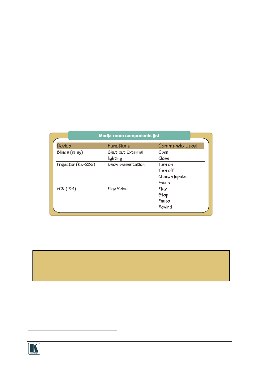
Make a detailed list of the functions and commands required of the system
devices, as illustrated in the partial list in Figure 1:
Figure 1: Media Room Components List
Once this list is finalized and approved, you can carry on with the
configuration and installation process.
Note that the RC configuration and installation processes are independent of
each other. You do not have to connect the RC device before starting the
configuration
1 Download up-to-date Kramer user manuals and guides from the Internet at this URL: http://www.kramerelectronics.com
3
Page 8

The RC Configuration Software
4 The RC Configuration Software
The Kramer RC Configuration 2 software lets you set a sequence of
commands (the macro) and assign them to any of the buttons on the RC
device.
The Kramer RC Configuration 2 software lets you:
Create your own device drivers manually or via the IR learner feature
Write, modify or delete commands
Change the order of commands within the macro
Set delay times between commands in a macro
Set the button lighting and color
Change text on the LCD displays on the RC units
Save multiple sets of RC device configurations
Read macros from the RC device
The RC buttons can be configured prior to installation
The following sections describe how to:
Install the software (see section 4.1)
Download the device drivers (see section 4.2)
Create Serial and IR commands (see section 4.2.3)
Map the ports (see section 4.3)
Use the Kramer RC Configuration main window (see section 4.4)
Write a macro (see section 4.4.1)
4.1 Installing the Software
Prior to using the Kramer RC Configuration 2 software, make sure that the
“.NET Framework” Revision 2.0 software is installed on your PC. If it is not,
you need to install it:
If you have a fast Internet connection, this software is automatically
installed during the installation of the Kramer RC Configuration 2
software
If you do not have a fast Internet connection, insert the CD-ROM into the
CD-ROM drive, double click the dotnetfx.exe1 file and follow the
on-screen instructions
1 File names are liable to change
2 Installation may take about 15 minutes
4
2
KRAMER: SIMPLE CREATIVE TECHNOLOGY
Page 9
The RC Configuration Software
Before getting started with your Kramer RC Configuration 2, you must
download the software and then install it. You can download it1 from the
Internet. To do so:
1. Go to our Web site at http://www.kramerelectronics.com and download the
file: “Kramer RC Config2.zip” from the DOWNLOADS section.
2. Extract the file “Kramer RC Config2.zip” package, which includes the
Kramer RC configuration 2 application setup and the Kramer device drivers2,
to a folder (for example, C:\Program Files\Kramer RC Configuration).
3. Install the Kramer RC Configuration 2 application.
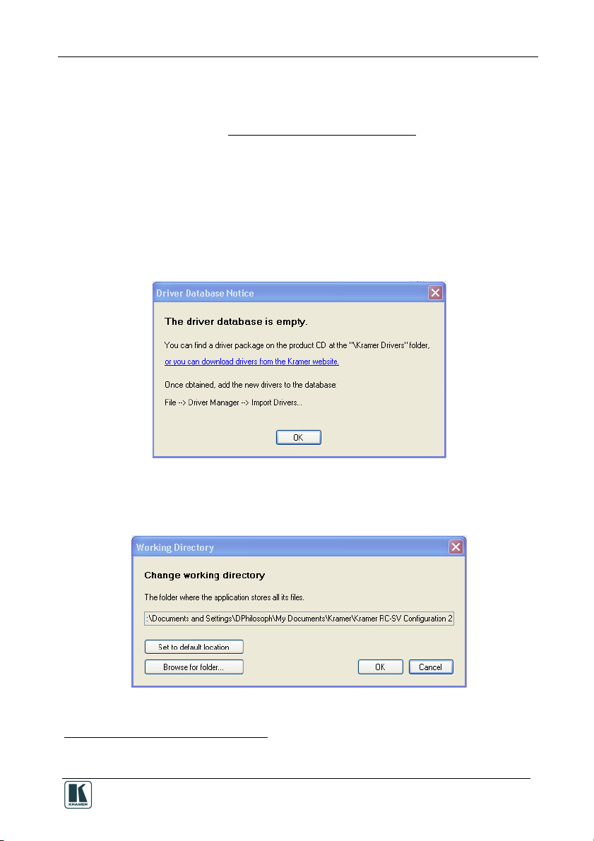
When running Setup, you are prompted to set the working directory (see
Figure 2):
Figure 2: Driver Database Notice
4. Click OK.
The following window appears (see Figure 3):
Figure 3: Setting a Working Directory
1 File names are liable to change from time to time
2 Mostly for matrix switchers and switchers
5
Page 10
The RC Configuration Software
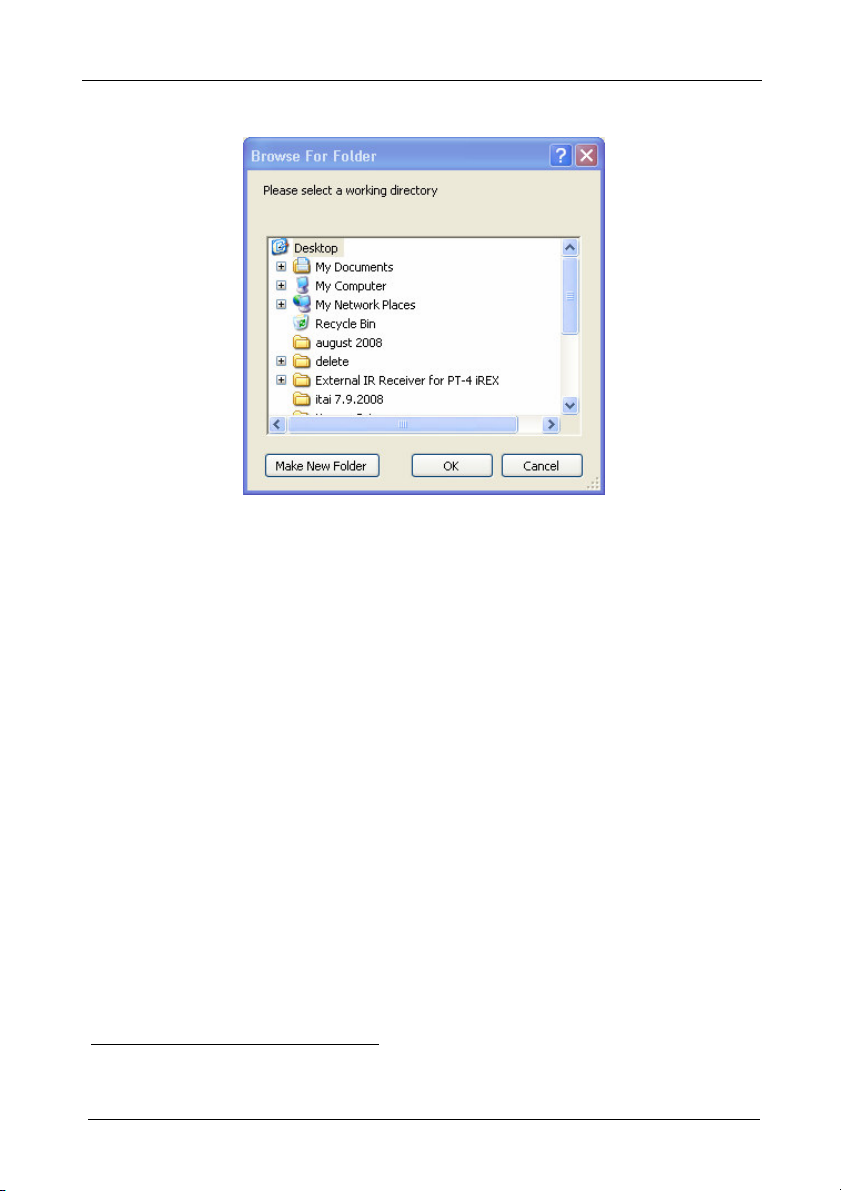
5. Select or create a new working directory1 (see Figure 4).
Figure 4: Change Working Directory Window
6. Continue to run the setup according to the installation instructions.
4.2 Downloading and Installing the Drivers
The RC system peripheral devices have device drivers that let them
communicate with computers. The device driver needs to be installed so that
the computer can recognize it and control it. The Kramer RC Configuration 2
software uses driver commands to control these peripheral devices.
4.2.1 Download the Drivers
Check—according to your list of peripheral devices (see the example in
Figure 1) —that you have all the required drivers:
Kramer machines have drivers that are provided within the package
Other peripheral device drivers that are included in the package
Download the required drivers to a folder (for example, C:\Media-Room1\Peripheral Device Drivers).
1 The working directory will keep the information that is essential for operating the software. This information will remain
unchanged while upgrading the software
6
KRAMER: SIMPLE CREATIVE TECHNOLOGY
Page 11
The RC Configuration Software
4.2.2 Install the Drivers
The peripheral device drivers are installed via the Driver Manager window,
defined in Figure 8 and Table 1:
To access the Driver Manager window:
1. Open the Kramer RC Configuration 2 program.
2. From the File menu, click Driver Manager.
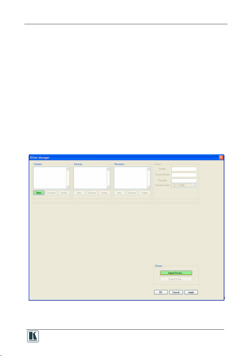
The Driver Manager window appears (see Figure 5).
When open, the Driver Manager window lets you:
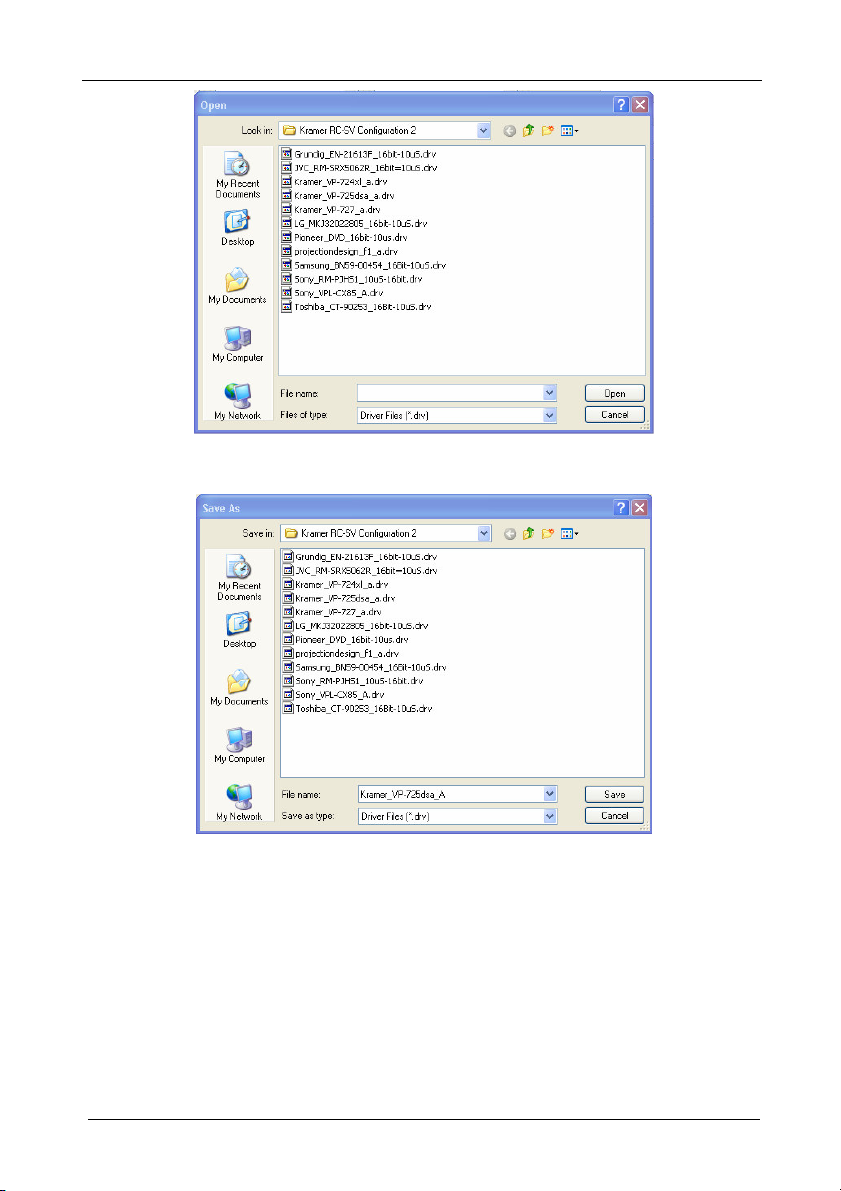
Import one or more drivers (Import Drivers…, see Figure 6), or export an
existing driver (Export Driver…, see Figure 7)
Add a new device driver
Rename or delete devices, revisions and commands, as defined in Table 1
Set the driver revision date
Write new commands
Figure 5: The Driver Manager Window Prior to Installing the Drivers
7
Page 12
The RC Configuration Software
Figure 6: Importing a Kramer Driver File
Figure 7: Exporting a Kramer Driver File
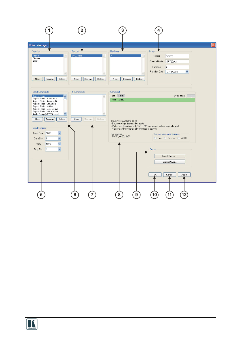
Figure 8 and Table 1 define the Driver Manager window:
8
KRAMER: SIMPLE CREATIVE TECHNOLOGY
Page 13
The RC Configuration Software
Figure 8: The Driver Manager Window
9
Page 14

The RC Configuration Software
Table 1: Driver Manager Window Features
# Feature Function
1 Vendors Area Lists the downloaded vendors
2 Devices Area Lists the names of devices of a selected vendor (in the Vendors area)
3 Revisions Area Lists the revision of a selected device
4 Driver Area Displays the selected Vendor, Device Model and Revision. Lets you set
5 Serial Settings Area Select the serial settings for the device: the Baud Rate, the Data Bits, the
6 Serial Commands Area Lists the serial command names for a specific device
7 IR Commands Area Lists the IR command names for a specific device
8 Command Area Displays the command type (see Figure 10 and Figure 13)
9 Drivers Area Import Drivers…: press to import one or more driver files
10 OK Button Apply changes and close window
11 Cancel Button Close window without applying changes
12 Apply Button Apply changes, but do not close window
New: press to enter a new vendor name manually
Rename: press to rename the vendor name
Delete: erases the selected vendor
New: press to enter a new device name manually
Rename: press to rename the device name
Delete: press to erase the selected device
New: press to enter a new revision manually
Rename: press to rename the revision number
Delete: press to erase the selected revision
the Revision Date
Parity and the Stop Bits
New: press to enter a new command name manually
Rename: press to rename the Command editing tab
Delete: press to erase the selected command
New: press to enter a new command name manually
Rename: press to rename the Command editing tab
Delete: erases the selected command
Export Driver…: press to export a driver file
10
KRAMER: SIMPLE CREATIVE TECHNOLOGY
Page 15

The RC Configuration Software
4.2.3 Creating a Driver Command
You can write two types of commands to a connected device (for example, a
DVD1):
Serial commands (see section 4.2.3.1)
IR commands (see section 4.2.3.2)
4.2.3.1 Creating a Serial Command
To write the serial commands for the selected device, click the New button in
the Serial Commands area. The New Serial Command window appears. Type
the new command name:
Figure 9: New Serial Command Window
A Serial Command type area appears, as illustrated in Figure 10.
Figure 10: Writing the Serial Commands
The serial commands created can be sent via the RS-232 and RS-485 ports.
1 Or a Kramer machine
11
Page 16

The RC Configuration Software
4.2.3.2 Creating an IR Command
To create IR commands for a selected device, connect the RC device directly1
to your PC via the USB connector and use the remote control transmitter2 to
learn its IR commands.
To write a new IR command to the RC device:
1. Click the New button in the IR commands area to type the new command
name.
The following window appears:
Figure 11: New IR Command Window
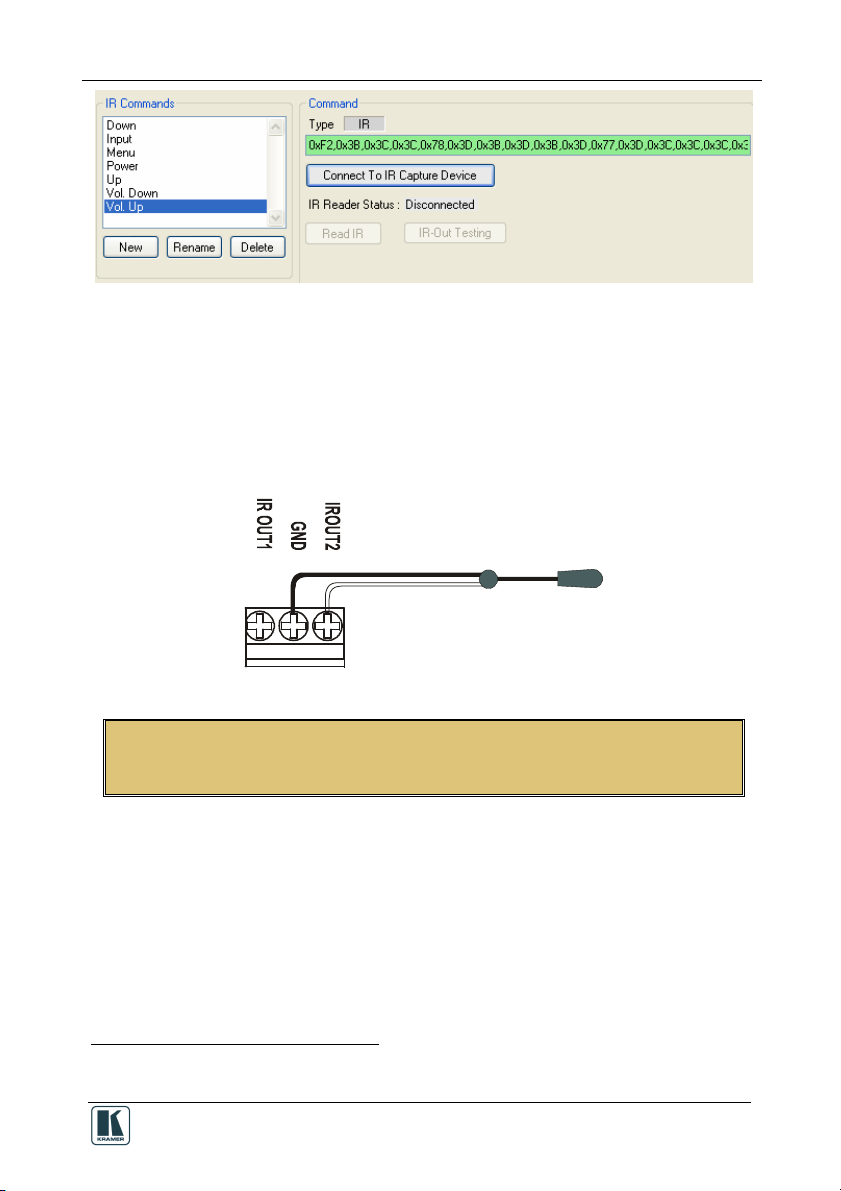
2. In the Command area, click the Connect to IR Capture Device button (see
Figure 13), select the port and click OK:
Figure 12: Connect to IR Capture Device Window
3. Click the Read IR button to read the command.
The command area displays the following message: “Ready for reading IR
command. Please send IR command to the device”.
4. Press the appropriate button on the remote control transmitter.
The command area displays the following message: “IR command reading”.
The IR command appears, as illustrated in Figure 13:
1 Whether it is defined as a Slave or a standalone Master
2 Of the machine from which you want to learn the IR commands. For example, use the DVD control transmitter to write the
DVD commands to the driver manager
12
KRAMER: SIMPLE CREATIVE TECHNOLOGY
Page 17
The RC Configuration Software
Figure 13: IR Command Area Window
You can test the IR command by connecting the RC unit IR terminal block
connectors to the device via the IR emitter, and then clicking the IR-Out
Testing button.
Figure 14 shows how to connect the IR emitter1. The white striped side
connects to IR OUT, the black side connects to the Ground, and the LED
Emitter Shell is affixed to the IR sensor window with the adhesive layer.
Figure 14: IR Emitter Wiring
NOTE: The dual IR emitter emits a weaker IR signal that may not be detected
by some devices
4.3 Port Mapping
The Port Manager window defines the ports on the Master device (SV-551 or
RC-6x, depending on the type of installation) and lets you write a description
and assign a default driver for each port. For example, if a DVD is connected
to the SV-551 via the IR_2 port, you can change the description next to that
port to “Sony DVD” and assign the Sony DVD driver to this port.
In this way, the Sony driver will be associated with the Sony DVD port
2
when
creating a command sequence as illustrated in Figure 15, making it easier to
1 Using the Kramer 3.5mm to IR Emitter Control Cable (C-A35/IRE-10)
2 Although you can assign it with a different Vendor or Device
13
Page 18

The RC Configuration Software
select the commands (also see section 4.4.1). The same applies to all the ports
in the Port Manager window.
Figure 15: The Sony DVD Player in the RC Command Area
For the RS-232 and RS-485 ports on the unit, the Port Manager window also
lets you set the baud rate, data bits, parity and stop bits.
To open the Port Manager window, click the “Port Manager…” item in the
Configuration menu (see section 6.3). Figure 16 shows the Port Manager
window for Kramer SV-551 SummitView™ Processor / Switcher1.
Figure 16: The Port Manager Window
1 Figure 51 shows the Port Manager window for the RC-6x stand alone setup
14
KRAMER: SIMPLE CREATIVE TECHNOLOGY
Page 19

The RC Configuration Software
Table 2: The Port Manager Window Features
The Item Description
Port Lists the ports available for the selected machine
Description Type a description of the port
Settings For serial ports, press the white area to open the serial Settings window and define the baud
Default Driver Press the white area to open the Drivers Tree window and select the default driver for this port
Reset Press to reset to default definitions
rate and parity
For Ethernet ports, press the white area to open the Ethernet Settings window and define the
IP address and TCP port
Press to clear the Default Driver data
4.4 The Kramer RC Configuration Main Window
After importing the drivers and defining the ports, use the Kramer RC
Configuration main window to assign a sequence of commands (the macro)
for each RC button. Figure 17 illustrates the Kramer RC Configuration 2 main
window, and Table 3 defines it:
Figure 17: The Kramer RC Configuration Main Window
15
Page 20

The RC Configuration Software
Table 3: Kramer RC Configuration Window Features
# Feature Function
1 Menu Bar Menus are described in section 6
Device Area
2 Name Box Displays the name of the specific device1
3 Connection Box Displays the connection properties with the device (IP address or
4 Master Box Select the Master device to which the slave keypad is connected.
5 Keypad Box Select the device type2
6 Slave Keypad Tab Shows the layout of the RC buttons according to the device type
7 Event Macros Tab By default, one event command sequence is assigned and can
8 Label Text Box Select a button and type the required button label
Button Area3
9
10 Write Configuration Button5 Press to write the configuration of all the buttons to the device
Behavior Dropdown Box
com port)1
Click the change button to change the master device type and
the Slave Keypad appearance (from a list)
selected, with the labels on the button. Click to Select a button to
configure, modify, read, or delete its macro.
When the button is:
Blue rimmed, it is assigned a command sequence
Green, it is selected
Gray, it is not assigned a macro
have commands added to it: Startup – a series of commands to be
executed upon unit startup (see Figure 18)
Assign the button response to press and release actions
Button Definition Behavior
Activate on Release
(default)
Activate while Pressed The macro is activated and repeated
Toggle 1-2-3-4 Cycling macro behavior:
Toggle Press-Release Dual macro behavior:
Disabled The button is disabled
The macro is executed upon releasing
the button
for as long as the button is pressed
The button can be assigned with up to
4 different macros. Each time it is
pressed, the next macro in the set will
be activated in a cyclic fashion.4
One macro is activated when pressing
the button and the other is activated
when releasing the button
1 The name and IP number are initially set by the Properties dialog box (see section 7.2)
2 The device type can be selected only if there is no device connected to the computer. If a device is connected, the device
type is selected automatically
3 The Button area appears only after selecting a button in the Front Panel tab
4 The number of toggle states can be determined (from 1 to 4). The selected number of toggle states appears above the Button
Macro area (see Figure 19)
5 This button is enabled only when a device is connected to the PC. Otherwise it is disabled
16
KRAMER: SIMPLE CREATIVE TECHNOLOGY
Page 21

The RC Configuration Software
# Feature Function
Button Macro Area
11 Button Macro Display Box Displays the macro RC commands’ Description, Delay and Port
New Command Button Click to add a new command to the Button Macro display box1
Duplicate Command Button Duplicate a command in the Button Macro display box
Delete Command Button Delete a command from the Button Macro display box
Button
Button
12 RC command Area (see section
4.4.1)
Description Text Box Optional descriptive text for the command
Port Drop-down Box Displays the port associated with the RC command: Select a port
13 Delay after command Text Box2 Set a delay time following the command3
15 Button lighting Area2 Select the buttons that will illuminate, turn dark or remain the same
in sequence. Select an RC command to duplicate, delete, or
change its position in the sequence
(see section 4.4.1)
Move up the selected command
Move down the selected command
Appears different for different ports and includes the following
features of the command selected in the Button Macro display
box:
when modifying or writing a new RC command
following a command (the lighting configuration can be different for
each command within the sequence). Toggle between ON (yellow),
OFF (black) and No Change (gray). You can also click reset to
reset the buttons to No Change (gray)
Figure 18 shows the Event Macros Tab:
Figure 18: Event Macros Tab
1 The button macro display box displays <No Description> under Description and None under Port
2 Shows after checking this option in the configuration menu (see section 6.3)
3 In seconds or milliseconds, via check box
17
Page 22

The RC Configuration Software
Figure 19 shows the Toggle button behavior:
Figure 19: Using the Toggle 1-2-3-4 Behavior
4.4.1 The RC Command Area
The RC Command area appears different for the various types of ports.
4.4.1.1 The IR, RS-232 and RS-485 Ports RC Command Area
Figure 20 and Table 4 define the IR, RS-232 and RS-485 Port Command area:
Figure 20: IR, RS-232 and RS-485 Port RC Command Area
Table 4: IR, RS-232 and RS-485 Port Command Area Features
Drop-down Box Description
Vendor Drop-down Box Displays the current vendor. Select the vendor when writing a
new RC command or modifying a selected command
Device Drop-down Box Displays the device driver name. Select the device driver when
modifying or writing a new RC command
Revision Drop-down Box Displays the device driver revision. Select a revision when
modifying or writing a new RC command
Driver command Drop-down Box Displays the current driver command. Select a driver command
when writing a new command or modifying a selected command
4.4.1.2 The Relay Port RC Command Area
The relay RC Command Area includes the Relay command drop-down box
(Close, Open):
Figure 21: Relay Port RC Command Area
18
KRAMER: SIMPLE CREATIVE TECHNOLOGY
Page 23

The RC Configuration Software
4.4.1.3 The Switcher Port RC Command Area
The switcher port command area includes the SV-551 Switcher command
drop-down box (Video 1, Video 2, PC1, PC2 and PC3):
Figure 22: Switcher Port RC Command Area
4.4.1.4 The Keypad LCD Port RC Command Area
The keypad LCD port RC Command area includes the LCD command dropdown box, which lets you type any text (up to 8 characters) to the LCD
display on the control device:
Figure 23: Switcher Port RC Command Area
4.4.1.5 The Button Color Port RC Command Area
The button color port RC Command area lets you select the button color and
state (On Off, Fast Blink and Slow Blink) for each button:
Figure 24: Button Color Port RC Command Area
19
Page 24

Creating a Macro
4.4.1.6 The Ignore Button Port RC Command Area
The Ignore/ Unignore command lets you control whether a press of a button
will issue the associated sequence of commands for that button. For example,
inserting "IGNORE button 4" into another button's command macro, will
actually disable button 4 until the "UNIGNORE button 4" command will be
issued from another command macro.
Figure 25: Ignore Button Port RC Command Area
5 Creating a Macro
A macro includes a sequence of commands assigned to a selected button on
the RC device.
To create a sequence of commands:
1. Press a button in the Slave Keypad tab to select the button to which you want
to write the macro. The button turns green:
Figure 26: Selecting a Button to Write a Macro
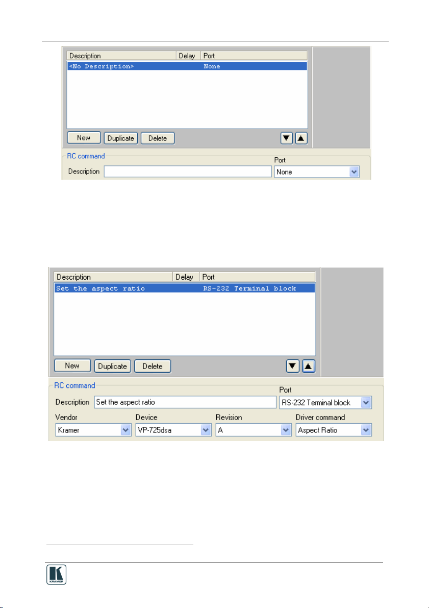
2. Click the New button in the Button Macro area:
20
KRAMER: SIMPLE CREATIVE TECHNOLOGY
Page 25
Creating a Macro
Figure 27: Creating a New Command
3. Select a port1 from the drop-down box (for example, the RS-232 terminal
block). The default driver appears.
4. Select a command from the Driver command area and write its description.
Click the up or down arrow to save the command to the macro:
Figure 28: Selecting the Port
5. Repeat this process to add new commands. Click Duplicate to duplicate the
command and delete a command by clicking the Delete button.
6. If required, set a delay time after the command or set the button lighting:
1 This is an example. The RC command area appears different for different ports, as described in section 5.2
21
Page 26

Creating a Macro
Figure 29: Setting the Delay Time and Button Lighting
5.1 Labeling the Buttons
For your convenience, you can label the buttons in the Slave Keypad tab area,
as illustrated in the example in Figure 30.
.
Figure 30: Labeling the RC Buttons
To label a button:
1. Open the Kramer RC Configuration main window.
2. Select a button.
3. Type the button text in the Label area:
Figure 31: Typing the Label
22
KRAMER: SIMPLE CREATIVE TECHNOLOGY
Page 27

Creating a Macro
5.2 Creating a Driver Command
The driver commands for each port are slightly different. The following
sections describe how to write a new command for the different ports.
5.2.1 An RS-232 Command – Switch Input to Output
To add a driver command to a button (for example, to switch the DVD player
to the projector), do the following:
1. Open the Port drop-down box and select the RS-232 Terminal Block (or IR
OUT or RS-485) port1 from the list2.
If a driver was assigned in the port mapping stage, the default driver associated
with this port appears.
2. In the RC command area, write the command description (for example,
SWITCH).
3. Select the Driver command (for example, “COMP!” ) from the drop-down
box2.
Figure 32 illustrates the RS-232 RC Command area as it appears after writing
the driver command:
Figure 32: Switch to COMP1 Command
1 Once the port is selected, the default driver details appear
2 If the required data does not exist, you can install it via the Manager Driver window (see section 4.1)
23
Page 28
Creating a Macro
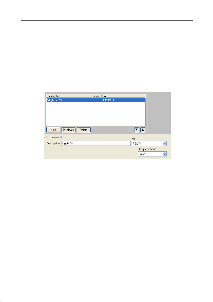
5.2.2 A Relay Command – Turn Lights ON
To write a relay command on an RC button (for example, turn the lights on),
do the following:
1. Select the Relay Port (for example, RELAY_1)
2. In the RC command area, write the command description (for example, Lights
ON).
3. Select the relay command (for example, Close).
Figure 33 illustrates the RC Command area as it appears after writing the
command:
Figure 33: Lights ON RC Command
5.2.3 A Switcher Command
Use the Switcher command to select an input connected to the Kramer
SV-551 (Video 1, Video 2, PC 1, PC2 and PC 3). The switcher command
applies to the master-slave configuration only.
To write a switcher command on an RC button, do the following:
1. Select the SWITCHER Port.
2. In the RC command area, write the command description (for example,
Select).
3. Select the switcher command (for example, Video 1).
Figure 34 illustrates the RC Command area as it appears after writing the
command:
24
KRAMER: SIMPLE CREATIVE TECHNOLOGY
Page 29

Creating a Macro
Figure 34: Switcher RC Command
5.2.4 A Power Amplifier Command
To write a power amplifier command1 on an RC button, do the following:
1. Select the POWER_AMP Port.
2. In the RC command area, write the command description (for example, High
Volume).
3. Select the power amplifier command (for example, Volume set).
4. Move the sliding switch to the desired volume (for example, 12dB).
Figure 34 illustrates the RC Command area as it appears after writing the
command:
Figure 35: High Volume RC Command
1 For the Master-Slave configuration only
25
Page 30

Creating a Macro
5.2.5 An LCD Keypad Command
The LCD Keypad command lets you type-in the desired text to the LCD
displays (LCD 1 and LCD 2).
To write an LCD keypad command on an RC button, do the following:
1. Select the KEYPAD_LCD Port (1 or 2).
2. In the RC command area, write the command description (for example,
Switcher).
3. Type-in the desired text.
Figure 34 illustrates the RC Command area as it appears after writing the
command:
Figure 36: Keypad LCD RC Command
5.2.6 Setting the Button State and Color
To write a Button Color command on an RC button, do the following:
1. Select the BUTTON_COLOR Port.
2. In the RC command area, write the command description (for example,
Change Color).
3. Select the Button ID (from 1 to 6) to which this command refers1.
4. Set the state of the button (On, Off, Fast Blink, Slow Blink), for example, On.
5. Set the Button Color (see Figure 38).
Figure 37 illustrates the RC Command area as it appears after writing the
command:
1 For example, the command is written to button 1 but refers to an action taken for button 4
26
KRAMER: SIMPLE CREATIVE TECHNOLOGY
Page 31

Creating a Macro
Figure 37: Change Color RC Command
Figure 38: Select Button Color
5.2.7 The Ignore Button Command
To write a Button Ignore command (see Figure 39) on an RC button (for
example, button 1), do the following:
1. Select the IGNORE BUTTON Port.
2. In the RC command area, write the command description (for example, Ignore
Button 4).
3. Select the Button ID (from 1 to 6) to which this command refers1, for example
button 4.
4. Set the state of the button (Ignore, Unignore), for example, Ignore.
1 For example, the command is written to button 1 but refers to an action taken for button 4
27
Page 32

The Kramer RC Configuration Menus
Figure 39 illustrates the RC Command area as it appears after writing the
command to button 1:
Figure 39: Ignore RC Command
6 The Kramer RC Configuration Menus
This section describes the Kramer RC Configuration menus.
6.1 The File Menu
Figure 40 illustrates the File menu and Table 5 defines it:
Figure 40: The File Menu
1 This will discard the active configuration
2 The working directory can be changed at any time
28
Table 5: File Menu Features
Menu Command Function
New Configuration Click to create a new
Save Configuration… Click to save the current
Load Configuration… Click to load a saved
Driver Manager … Click to open the Manage
Change Working
Directory…
Exit Click to exit the program.
device configuration1.
configuration.
configuration.
Drivers window (see
section 4.2.2).
Click to set the new
working directory2.
KRAMER: SIMPLE CREATIVE TECHNOLOGY
Page 33

The Kramer RC Configuration Menus
6.2 The Edit Menu
Figure 41 illustrates the Edit menu and Table 6 defines it:
Table 6: Edit Menu Features
Menu Command Function
Figure 41: The Edit Menu
Copy Macro Click to copy a button macro
Paste Macro Click to paste a button macro
Clear Macro Click to clear the Macro-
Clear Button labels Click to clear all the button
command sequence.
command sequence.
commands sequence box.
labels.
6.3 The Configuration Menu
Figure 42 illustrates the Configuration menu and Table 7 defines it:
Table 7: Configuration Menu
Menu
Command
Port Manager Lists the ports names,
Show Delay Check to show in RC
Figure 42: The Configuration Menu
Show Button
Lighting
Features
Function
description, settings and
drivers (see section 4.3).
main configuration
window.
Check to show in RC
main configuration
window.
29
Page 34

The Kramer RC Configuration Menus
6.4 The Device Menu
Figure 43 illustrates the Device menu and Table 8 defines it:
Table 8: Device Menu Features
Menu Command Function
Connect… Click to connect to a device via
Disconnect Click to disconnect the device
Properties1 Click to show the device
Write Configuration1 Writes the configuration to the
Load Firmware Load file for firmware upgrade.
Set As Slave Enabled when the RC is
an IP number or serial port.
properties dialog box.
device.
connected as a stand alone unit.
Lets you set the device as a
slave. The RC controller will
automatically disconnect.
Figure 43: The Device Menu
6.4.1 The Connect Command
To connect a device, do the following:
1. Open the Device menu and click Connect.
The Connect window appears (see Figure 44).
2. Select the Connection method and type the IP number of the desired device (or
port).
Table 9: Connect Dialog Box
Feature Function
Connection
Method Area
Ethernet Area IP: Type the IP number of the
USB Area Port: select the communication USB
Figure 44: Device Selection Dialog Box
1 Active only when a device is connected
30
Check Ethernet to select
connection to the device via the
Ethernet.
Check Usb to select connection to
the device via a USB connector.
device you want to connect to.
Port: shows the port number.
Factory Default Address Button:
Press to reset the IP number to its
default value.
port.
Refresh ports: click to check if there
are ports ready to connect on the
Kramer device.
KRAMER: SIMPLE CREATIVE TECHNOLOGY
Page 35

The Kramer RC Configuration Menus
6.4.2 The Device Properties Dialog Box
To connect a device, open the Device menu and click Properties. The Device
Properties window Appears (see Figure 45). Figure 52 shows the Device
Properties window in the stand alone setup.
Table 10: Connect Dialog Box
Feature Function
Figure 45: Device Properties Window
Name, IP, Gateway,
Mask
Model, Serial number,
Port, Firmware, K-NetID, MAC,
DHCP1 Enabled Check box to enable operation in
If required, change information.
Displays information.
the DHCP mode.
When in the DHCP mode, you
can only change the name of the
device.
This process may take several
minutes and will cause an
automatic restart on the device.
6.5 The Help Menu
Figure 46 illustrates the Help menu and Table 11 defines it:
Table 11: Help Menu Features
Menu Command Function
Figure 46: The Help Menu
Check for updates Search the Kramer
About Kramer RC
Configuration
Electronics Web site for
software updates.
Shows the current software
version.
1 Dynamic Host Configuration Protocol: Allows the network administrator to distribute IP addresses from a central point and
automatically send a new IP address when an Ethernet point is plugged into a different network location
31
Page 36

The Kramer RC Configuration Menus
6.6 Load Firmware
To load new firmware:
1. From the Device menu select Load Firmware.
The Load Firmware Upgrade window appears:
Figure 47: Load Firmware Upgrade Window (SV-551)
2. Click the Browse button to find the firmware file.
3. Select the machine from the drop-down list box1.
1 When selecting a room controller device such as RC-6x, you have to select the connection method: Direct connection or
Connection via SV-551 via K-NET
32
KRAMER: SIMPLE CREATIVE TECHNOLOGY
Page 37

The Kramer RC Configuration Menus
Figure 48: Load Firmware Upgrade Window (RC-6x)
4. Connect to the device.
5. Click the Connect button to connect the device and then click Start Upgrade.
6. Upon completion, open the Device Properties window (see Figure 45) to make
sure the firmware was upgraded1.
1 If the firmware number remains the same, close the Device Properties windows, disconnect and then reconnect the device,
and open the Device Properties window again to check the firmware number
33
Page 38

Connecting a Room Controller as a Stand Alone Device (Master)
7 Connecting a Room Controller as a Stand Alone Device
(Master)
You can configure the Room Controller to be used as a standalone device. To
do this you have to connect the Room controller directly to your PC via the
USB connector.
To define the RC as a Master device:
1. From the Device Menu, click Connect… .
2. Select the connection method to be USB, select the port and click OK.
The following warning appears:
Figure 49: Transforming to the Stand Alone Configuration
3. Click Yes.
The room controller is now stand alone and the Device description appears as
follows:
Figure 50: Standalone Device Description
When in the stand alone mode, you can write the command sequences directly
to the room controller by clicking the Write Configuration button in the
Device area (see section 9).
The following windows will appear differently when in the standalone mode:
The Port Manager window, see section 7.1
The Device Properties window, see section 7.2
34
KRAMER: SIMPLE CREATIVE TECHNOLOGY
Page 39

Connecting a Room Controller as a Stand Alone Device (Master)
7.1 The Port Manager in the Stand Alone Mode
The Port Manager displays the ports relevant to the room controller, as
illustrated in Figure 51:
Figure 51: The Port Manager in the Stand Alone Mode
7.2 The Device Properties Window in the Stand Alone Mode
Figure 52 shows the Device Properties window in the stand alone mode:
Figure 52: The Device Properties Window in the Stand Alone Mode
To exit the stand alone mode open the Device menu and select Set as Slave.
35
Page 40

Connecting via the ETHERNET
8 Connecting via the ETHERNET
You can connect the SV-551 via the Ethernet, using a crossover cable (see
section 8.1) for direct connection to the PC or a straight through cable (see
section 8.2) for connection via a network hub or network router.
8.1 Connecting the ETHERNET Port directly to a PC (Crossover
Cable)
You can connect the Ethernet port of the RC device to the Ethernet port on your
PC, via a crossover cable with RJ-45 connectors.
This type of connection is recommended for identification of the factory default
IP Address of the RC device (192.168.1.39) during the initial configuration
After connecting the Ethernet port, configure your PC as follows:
1. Right-click the My Network Places icon on your desktop.
2. Select Properties.
3. Right-click Local Area Connection Properties.
4. Select Properties.
The Local Area Connection Properties window appears.
5. Select the Internet Protocol (TCP/IP) and click the Properties Button (see
Figure 53).
36
Figure 53: Local Area Connection Properties Window
KRAMER: SIMPLE CREATIVE TECHNOLOGY
Page 41

Writing a Configuration
6. Select Use the following IP Address, and fill in the details as shown in
Figure 54.
7. Click OK.
Figure 54: Internet Protocol (TCP/IP) Properties Window
8.2 Connecting the ETHERNET Port via a Network Hub (StraightThrough Cable)
You can connect the Ethernet port of the RC device to the Ethernet port on a
network hub or network router, via a straight-through cable with RJ-45
connectors.
9 Writing a Configuration
Once your configuration is ready, you can write it to the device, via the “Write
Configuration” button.
Note that if the room controller is defined as a:
Master (stand alone), the configuration is written directly to the device
Slave device (the room controller is connected to the SV-551), the
configuration is written to the SV-551
In case you have written the configuration to a stand alone device and it is
now connected as a slave to the SV-551, you have to write the configuration
once again after defining the device as a slave.
37
Page 42

Writing a Configuration
To write a configuration to the device, do the following:
1. Connect the PC to the:
RC-6x (stand alone) to write the configuration directly to the RC-6x
SV-551 (in a SummitView™ kit setup) to write the configuration to
the SV-551
2. From the File menu, select Load Configuration1… .
The Open window appears (see Figure 55).
3. Click Open1
4. In the Device area in the RC Configuration 2 main window, click the Write
Configuration button2.
The configuration is written to the device.
Figure 55: Loading a Configuration
1 Skip this step if you have the desired configuration loaded
2 The Write Configuration button is enabled only when the device is connected
38
KRAMER: SIMPLE CREATIVE TECHNOLOGY
 Loading...