

Page 1

Kramer Electronics, Ltd.
USER MANUAL
Models:
RB-8,
RB-8E,
8 Channel Power Controller
8 Channel Power Controller
Page 2

Contents
Contents
1
Introduction 1
2
Getting Started 1
2.1 Quick Start 2
3
Overview 3
4
Your RB-8/RB-8E 8 Channel Power Controller 3
5
Installing the RB-8/RB-8E in a Rack 5
6
Connecting the RB-8/RB-8E 6
7
Operating the RB-8/RB-8E 7
8
Technical Specifications 7
Figures
Figure 1: RB-8 / RB-8E Front Panel 4
Figure 2: RB-8 Rear Panel 4
Figure 3: RB-8E Rear Panel 4
Figure 4: Connecting the RB-8 6
Tables
Table 1: RB-8/RB-8E 8 Channel Power Controller Functions 3
Table 2: RB-8/RB-8E Technical Specifications 7
i
Page 3

Introduction
1 Introduction
Welcome to Kramer Electronics! Since 1981, Kramer Electronics has been
providing a world of unique, creative, and affordable solutions to the vast
range of problems that confront the video, audio, and presentation
professional on a daily basis. In recent years, we have redesigned and
upgraded most of our line, making the best even better! Our 500-plus
different models now appear in eight groups1 that are clearly defined by
function.
Thank you for purchasing the Kramer RB-8/RB-8E 8 Channel Power
Controller, which is ideal for:
Production studios
Large multimedia displays
Home entertainment installations
Each package includes the following items:
The RB-8/RB-8E 8 Channel Power Controller. (The RB-8 is a
model for use in America with 110V AC American power
sockets, and the RB-8E is for use in Europe with 220V AC
European power sockets)
Power cord2
This user manual3
2 Getting Started
We recommend that you:
Unpack the equipment carefully and save the original box and
packaging materials for possible future shipment
Review the contents of this user manual
Use Kramer high-performance high resolution cables4
1 GROUP 1: Distribution Amplifiers; GROUP 2: Video and Audio Switchers, Matrix Switchers and Controllers; GROUP 3:
Video, Audio, VGA/XGA Processors; GROUP 4: Interfaces and Sync Processors; GROUP 5: Twisted Pair Interfaces;
GROUP 6: Accessories and Rack Adapters; GROUP 7: Scan Converters and Scalers; and GROUP 8: Cables and Connectors
2 We recommend that you use only the power cord supplied with this device
3 Download up-to-date Kramer user manuals from our Web site at http://www.kramerelectronics.com
4 The complete list of Kramer cables is on our Web site at http://www.kramerelectronics.com
1
Page 4
Getting Started
2.1 Quick Start
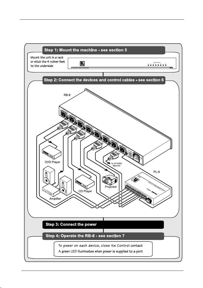
This quick start chart summarizes the basic setup and operation steps.
2
KRAMER: SIMPLE CREATIVE TECHNOLOGY
Page 5

Overview
3 Overview
The Kramer RB-8 is a high-performance, high-voltage power supply that
supplies power to up to eight external units. Each output channel includes a
power socket and a 2-pin terminal block control port. When the control port
is connected, the contact-closure supplies power to that channel. LEDs on
the front panel indicate which ports are supplying power to their devices.
The RB-8 is housed in a 19-inch, 1U rack-mountable enclosure, and is
powered by a 100–240V AC universal switching power supply. The RB-8
is a model for use in America with 110V AC American power sockets, and
the RB-8E is for use in Europe with 220V AC European power sockets.
“RB-8” is printed on the front panel of both models.
To achieve the best performance:
1
Use only good quality connection cables
to avoid interference,
deterioration in signal quality due to poor matching, and elevated
noise levels (often associated with low quality cables).
Avoid interference from neighboring electrical appliances that
may adversely influence signal quality and position your Kramer
RB-8 away from moisture, excessive sunlight and dust
4 Your RB-8/RB-8E 8 Channel Power Controller
Table 1, Figure 1, Figure 2, and Figure 3 define the unit.
Table 1: RB-8/RB-8E 8 Channel Power Controller Functions
#
1 ACTIVE OUTPUT LEDs Illuminate green when supplying power (from 1 to 8)
2 OUT Female power socket AC connector enabling power supply to the attached unit
3 CONTROL Pin When grounded, the port powers ON (from 1 to 8)
4 GND (Ground) Pin Ground for control contact (from 1 to 8)
5 POWER Switch Illuminated switch for turning the unit ON and OFF
6 POWER IN with fuse
Feature
(from 1 to 8)
AC connector supplying power to the RB-8
Function
1 Available from Kramer Electronics on our Web site at http://www.kramerelectronics.com
3
Page 6

KRAMER: SIMPLE CREATIVE TECHNOLOGY
Figure 2: RB-8 Rear Panel
Figure 1: RB-8 / RB-8E Front Panel
Your RB-8/RB-8E 8 Channel Power Controller
Figure 3: RB-8E Rear Panel
4
Page 7

Installing the RB-8/RB-8E in a Rack
5 Installing the RB-8/RB-8E in a Rack
This section describes how to install the RB-8/RB-8E in a rack.
Before Installing on a Rack
Before installing on a rack, be sure that the environment is
within the recommended range:
Operating temperature range +5º to +45º C (41º to 113º F)
Operating humidity range 10 to 90% RHL, non-condensing
Storage temperature range -20º to +70º C (-4º to 158º F)
Storage humidity range 5 to 95% RHL, non-condensing
When installing on a 19" rack, avoid hazards by taking
CAUTION!!
care that:
1. It is located within the recommended environmental
conditions, as the operating ambient temperature of a
closed or multi unit rack assembly may exceed the
room ambient temperature.
2. Once rack mounted, enough air will still flow around
the machine.
3. The machine is placed straight in the correct
horizontal position.
4. You do not overload the circuit(s). When connecting
the machine to the supply circuit, overloading the
circuits might have a detrimental effect on overcurrent
protection and supply wiring. Refer to the appropriate
nameplate ratings for information. For example, for
fuse replacement, see the value printed on the
product label.
5. The machine is earthed (grounded) in a reliable way
and is connected only to an electricity socket with
grounding. Pay particular attention to situations where
electricity is supplied indirectly (when the power cord
is not plugged directly into the socket in the wall), for
example, when using an extension cable or a power
strip, and that you use only the power cord that is
supplied with the machine.
To rack-mount a machine:
1. Attach both ear brackets to the
machine. To do so, remove the
screws from each side of the
machine (3 on each side), and
replace those screws through the
ear brackets.
2. Place the ears of the machine
against the rack rails, and insert the
proper screws (not provided)
through each of the four holes in the
rack ears.
Note that:
In some models, the front panel
may feature built-in rack ears
Detachable rack ears can be
removed for desktop use
Always mount the machine in the
rack before you attach any cables
or connect the machine to the
power
If you are using a Kramer rack
adapter kit (for a machine that is not
19"), see the Rack Adapters user
manual for installation instructions
(you can download it at:
http://www.kramerelectronics.com)
How to Rack Mount
5
Page 8

Connecting the RB-8/RB-8E
6 Connecting the RB-8/RB-8E
To connect the RB-8/RB-8E, as illustrated in Figure 4, do the following:
1. Connect the power cable from each external device to any free power output
port on the RB-8/RB-8E.
2. Connect a switched cable to the CONTROL/GROUND contact of the same
port (for example, from the PL-8 Low Voltage Relay Controller as shown in
Figure 2.)
3. Connect the power cord to the RB-8/RB-8E (not illustrated in Figure 2.)
Figure 4: Connecting the RB-8
6
KRAMER: SIMPLE CREATIVE TECHNOLOGY
Page 9

Operating the RB-8/RB-8E
7 Operating the RB-8/RB-8E
To operate the RB-8/RB-8E:
Turn on the power on the RB-8/RB-8E.
Power on each external device by closing the CONTROL contact
associated with its port.
Each port that supplies power is indicated by an illuminated LED on the
front panel.
8 Technical Specifications
The RB-8/RB-8E technical specifications are shown in Table 2:
Table 2: RB-8/RB-8E Technical Specifications1
POWER SOURCE: 110–220V AC
POWER OUTPUT: RB-8: 16A (2.0A maximum output with 8 connections)
DIMENSIONS 19" x 7" x 1U W, D, H
WEIGHT: 2.0kg (4.4lbs)
ACCESSORIES: Power cord (American or European depending on the model), rack ears
RB-8E: 10A (1.25A maximum output with 8 connections)
1 Specifications are subject to change without notice
7
Page 10

8
KRAMER: SIMPLE CREATIVE TECHNOLOGY
Page 11

For the latest information on our products and a list of Kramer
distributors, visit our Web site: www.kramerelectronics.com
where updates to this user manual may be found.
We welcome your questions, comments and feedback.
Safety Warning:
Disconnect the unit from the power supply before
opening/servicing.
Caution
Kramer Electronics, Ltd.
Web site: www.kramerelectronics.com
E-mail: info@kramerel.com
P/N: 2900-000351 REV 1
 Loading...