

Page 1

KRAMER ELECTRONICS L T D .
P/N: 2900
USER MANUAL
MODEL:
RB -6
6 Channel Power Controller
-30 0024 Rev 1
Page 2
Page 3

RB-6 – Contents
i
Contents
1 Introduction 1
2 Getting Started 2
2.1 Achieving the Best Performance 2
2.2 Safety Instructions 2
2.3 Recycling Kramer Products 3
3 Overview 4
3.1 Using the IR Transmitter 4
4 Defining the RB-6 6 Channel Power Controller 5
5 Installing in a Rack 8
6 Connecting the RB-6 9
6.1 Connecting Devices to the RB-6 9
6.2 Connecting to the RB-6 via Ethernet 10
6.3 Connecting to the RB-6 via RS-232 14
6.4 Connecting a PC or Controller to the RS-485 Port 15
7 Operating the RB-6 Locally 17
7.1 Operating the RB-6 via the Front Panel Buttons 17
7.2 Resetting the RB-6 to Factory Defaults 18
8 Operating the RB-6 Remotely Using the Web Pages 19
8.1 Accessing the RB-6 Embedded Web Pages 19
8.2 The Panel Page 21
8.3 The Scheduler Page 22
8.4 The Configurations Page 23
9 Firmware Update 25
10 Technical Specifications 26
11 Default Communication Parameters 27
12 RB-6 Communication Protocol 28
12.1 Syntax 28
12.2 Supported Commands 31
Figures
Figure 1: RB-6 6 Channel Power Controller Front and Rear Panels 5
Figure 2: RB-6 (US) 6 Channel Power Controller Front and Rear Panels 6
Figure 3: Connecting to the RB-6 Rear Panel 9
Figure 4: Local Area Connection Properties Window 11
Figure 5: Internet Protocol (TCP/IP) Properties Window 11
Figure 6: K-Upload Main Screen 12
Figure 7: Connect Screen 13
Figure 8: Device Properties Screen 14
Figure 9: Crossed Cable RS-232 Connection 15
Figure 10: Straight Cable RS-232 Connection with a Null Modem Adapter 15
Figure 11: Entering the IP Address in your Browser 19
Figure 12: Loading the Embedded Web Pages 20
Figure 13: Security Warning 20
Page 4

ii
RB-6 - Introduction
Figure 14: Panel Page 21
Figure 15: The Scheduler Page 22
Figure 16: The Configurations Page 23
Page 5

RB-6 – Introduction
1
1 Introduction
Welcome to Kramer Electronics! Since 1981, Kramer Electronics has been
providing a world of unique, creative, and affordable solutions to the vast range of
problems that confront video, audio, presentation, and broadcasting professionals
on a daily basis. In recent years, we have redesigned and upgraded most of our
line, making the best even better!
Our 1,000-plus different models now appear in 11 groups that are clearly defined
by function: GROUP 1: Distribution Amplifiers; GROUP 2: Switchers and Routers;
GROUP 3: Control Systems; GROUP 4: Format/Standards Converters; GROUP 5:
Range Extenders and Repeaters; GROUP 6: Specialty AV Products; GROUP 7:
Scan Converters and Scalers; GROUP 8: Cables and Connectors; GROUP 9:
Room Connectivity; GROUP 10: Accessories and Rack Adapters and GROUP 11:
Sierra Video Products.
Congratulations on purchasing your Kramer RB-6 6 Channel Power Controller,
which is ideal for the following typical applications:
Production studios
Large multimedia displays
Home entertainment installations
Page 6
2
RB-6 - Getting Started
Go to http://www.kramerelectronics.com/support/product_downloads.asp
to check for up-to-date user manuals, application programs, and to check if
firmware upgrades are available (where appropriate).
This equipment is to be used only inside a building. It may only be
connected to other equipment that is installed inside a building.
Caution:
There are no operator serviceable parts inside the unit
Warning:
You use only the power cord that is supplied with the
unit. Do not open the unit. High voltages can cause
electrical shock! Servicing by qualified personnel only
Warning:
Disconnect the power and unplug the unit from the wall
before installing
i
!
!
2 Getting Started
We recommend that you:
Unpack the equipment carefully and save the original box and packaging
materials for possible future shipment
Review the contents of this user manual
2.1 Achieving the Best Performance
To achieve the best performance:
Use only good quality connection cables to avoid interference (often
associated with low quality cables)
Do not secure the cables in tight bundles or roll the slack into tight coils
Position your Kramer RB-6 away from moisture, excessive sunlight and dust
2.2 Safety Instructions
Page 7

RB-6 – Getting Started
3
2.3 Recycling Kramer Products
The Waste Electrical and Electronic Equipment (WEEE) Directive 2002/96/EC
aims to reduce the amount of WEEE sent for disposal to landfill or incineration by
requiring it to be collected and recycled. To comply with the WEEE Directive,
Kramer Electronics has made arrangements with the European Advanced
Recycling Network (EARN) and will cover any costs of treatment, recycling and
recovery of waste Kramer Electronics branded equipment on arrival at the EARN
facility. For details of Kramer’s recycling arrangements in your particular country
go to our recycling pages at http://www.kramerelectronics.com/support/recycling/.
Page 8

4
RB-6 - Overview
3 Overview
The Kramer RB-6 is a high-performance, high-voltage power supply that supplies
power to up to six external units.
The RB-6 features:
Two power outlets with on/off push-button as well as full voltage control
Four power outlets with on/off push-button control
Individual push-button LEDs to indicate which outlets are live
Remote control via Ethernet (with built-in Web pages), RS-232 and RS-485
Availability in European and American versions
The RB-6 is housed in a 19-inch, 1U, rack-mountable enclosure and is powered
by a 100–240V AC universal switching power supply. The RB-6 is for use in
Europe with 220V AC European power sockets and the RB-6 (US) is for use in
America with 110V AC American power sockets. RB-6 is printed on the front panel
of both models.
3.1 Using the IR Transmitter
You can use the RC-IR3 IR transmitter to control the machine via the built-in IR
receiver on the front panel or instead, via an optional external IR receiver (Model:
C-A35M/IRR-50). The external IR receiver can be located up to 15m (49ft) away
from the machine. This distance can be extended to up to 60m (197ft) when used
with three extension cables (Model: C-A35M/A35F-50).
Before using the external IR receiver be sure to arrange for your Kramer dealer to
insert the internal IR connection cable (P/N: 505-70434010-S) with the 3.5mm
connector that fits into the REMOTE IR opening on the rear panel. Connect the
external IR receiver to the REMOTE IR 3.5mm connector.
Page 9
5
RB-6 – Defining the RB
-6 6 Channel Power Controller
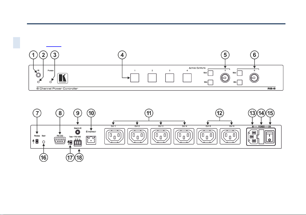
4 Defining the RB-6 6 Channel Power Controller
Figure 1 defines the RB-6 6 Channel Power Controller.
Figure 1: RB-6 6 Channel Power Controller Front and Rear Panels
Page 10
RB-6 – Defining the RB
-6 6 Channel Power Controller
6
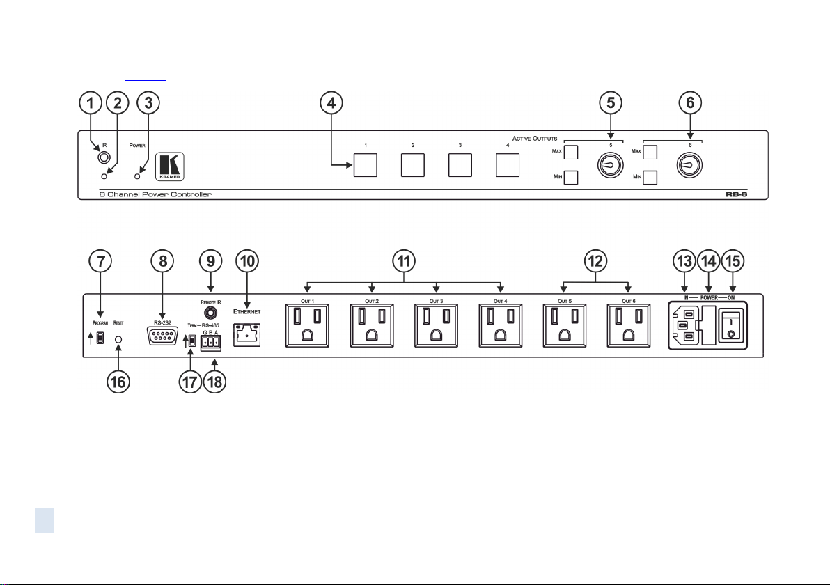
Figure 2 defines the RB-6 (US) 6 Channel Power Controller.
Figure 2: RB-6 (US) 6 Channel Power Controller Front and Rear Panels
Page 11

RB-6 - Defining the RB-6 6 Channel Power Controller
7
7
#
Feature
Function
1
IR Receiver
Infrared remote control sensor
2
IR LED
Lights yellow when receiving commands from the IR remote control
transmitter
3
POWER LED
Lights green when the device is powered on
4
ACTIVE OUTPUTS
Buttons (1 to 4)
Press a button to turn on the output. The relevant button LED lights
red.
Press the button again to turn the output off. The button LED no
longer lights
5
ACTIVE
OUTPUTS 5
Controls
MAX
Press to set the output voltage to maximum. Press and hold to set
the current setting as the maximum voltage
MIN
Press to set the output voltage to minimum. Press and hold to set
the current setting as the minimum voltage
Rotary
control
Turn clockwise to increase or anti-clockwise to decrease the output
voltage
6
ACTIVE
OUTPUTS 6
Controls
MAX
Press to set the output voltage to maximum. Press and hold to set
the current setting as the maximum voltage
MIN
Press to set the output voltage to minimum. Press and hold to set
the current setting as the minimum voltage
Rotary
control
Turn clockwise to increase or anti-clockwise to decrease the output
voltage
7
PROGRAM Switch
For the use of Kramer service personnel only
8
RS-232 9-pin D-sub
Connector (F)
Connect to an RS-232 controller, such as a PC (see Section 6.3)
9
REMOTE IR 3.5mm
Opening
For installing the optional external IR receiver 3.5mm mini jack (see
Section 3.1)
10
ETHERNET RJ-45
Connector
Connect to a remote PC controller over a LAN (see Section 6.2)
11
OUT 1~4 Power Sockets
Plug in devices to be controlled only on and off
12
OUT 5~6 Power Sockets
Plug in devices to be controlled on/off, and a dimming function using
the minimum/maximum rotary controls (see 5 and 6)
13
IN—POWER—ON
Power Socket
Connect to the mains power
14
Mains Fuse
Fuse for protecting the RB-6
15
Mains Switch
Switch for turning the device on and off
16
RESET Switch
Press and hold while turning power on to reset the device to factory
default condition
17
TERM RS-485 Switch
Push up to terminate the RS-485 bus (see Section 6.4)
18
RS-485 3-pin Terminal
Block
Connect to a controller equipped with an RS-485 port (see
Section 6.4)
The following table refers to both Figure 1 and Figure 2.
Page 12
8
RB-6 - Installing in a Rack
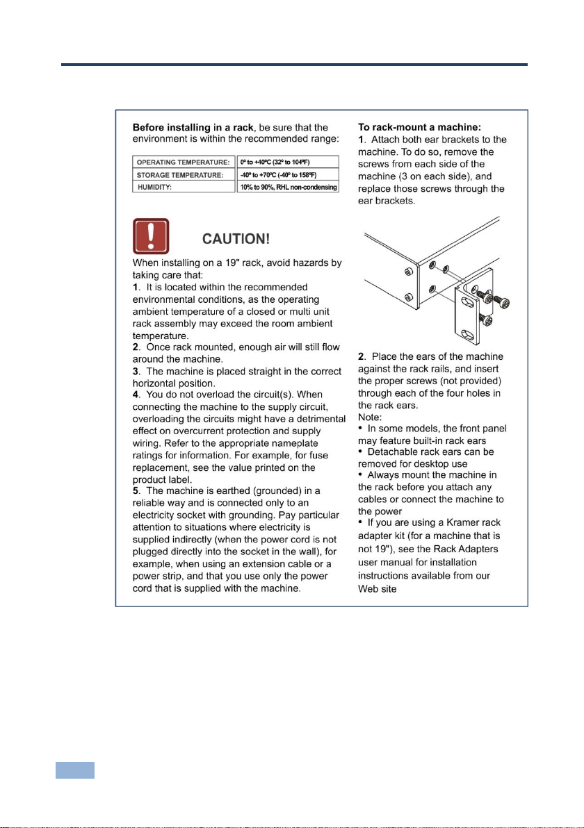
5 Installing in a Rack
Page 13

RB-6 - Connecting the RB-6
9
9
Always switch off the power to all devices before connecting them to
your RB-6. After connecting your RB-6, connect its power and then
switch on the power to each device.
!
6 Connecting the RB-6
6.1 Connecting Devices to the RB-6
Figure 3: Connecting to the RB-6 Rear Panel
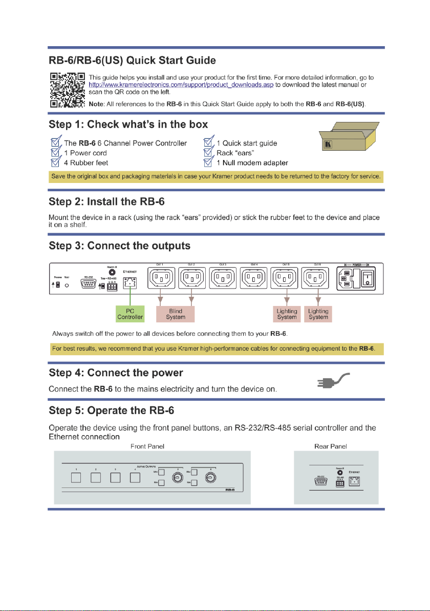
To connect the RB-6 as illustrated in the example in Figure 3:
1. Connect a device, (for example, a blind system) to power outlet 1 for open
and to power outlet 2 for close control.
2. Connect a device, (for example, a lighting system) to power outlet 6 for
on/off control and a dimming function.
Page 14

10
RB-6 - Connecting the RB-6
3. Optional—connect a PC via Ethernet over a LAN to the RB-6 for remote
control.
6.2 Connecting to the RB-6 via Ethernet
You can connect the RB-6 via Ethernet using a crossover cable (see
Section 6.2.1) for direct connection to the PC, or a straight through cable (see
Section 6.2.2) for connection via a network hub or network router.
After connecting the Ethernet port, you have to install and configure your Ethernet Port. For
detailed instructions, see the Ethernet Configuration Guide (Lantronix) in the technical support
section on our Web site http://www.kramerelectronics.com
6.2.1 Connecting the Ethernet Port directly to a PC
You can connect the Ethernet port on the RB-6 to the Ethernet port on your PC
via a crossover cable with RJ-45 connectors.
This type of connection is recommended for identification of the
factory default IP Address of the RB-6 during the initial configuration
To configure your PC after connecting the Ethernet port:
1. Right-click the My Network Places icon on your desktop.
2. Select Properties.
3. Right-click Local Area Connection Properties.
4. Select Properties.
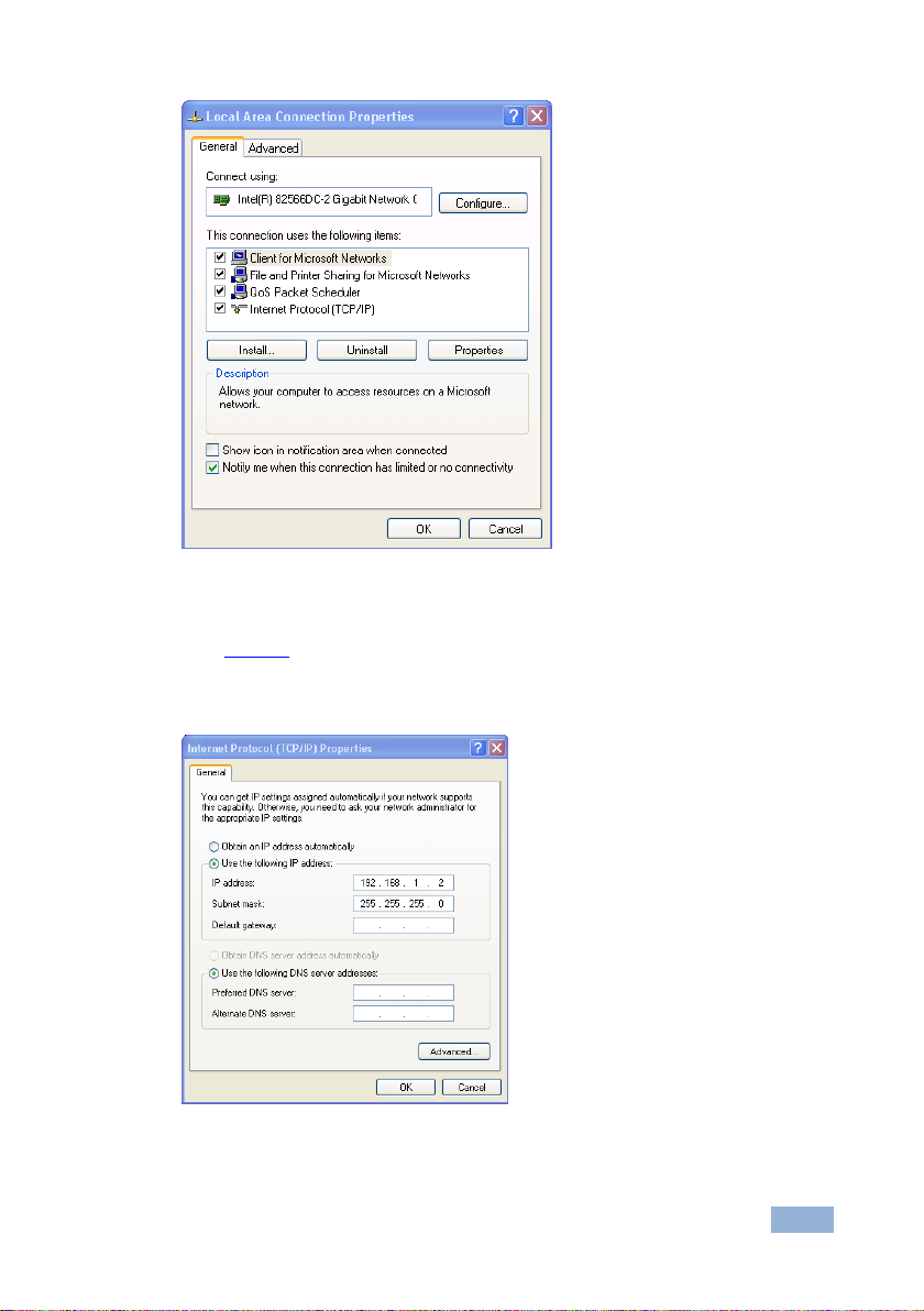
The Local Area Connection Properties window appears.
5. Select the Internet Protocol (TCP/IP) and click the Properties Button.
Page 15
RB-6 - Connecting the RB-6
11
11
Figure 4: Local Area Connection Properties Window
6. Select Use the following IP Address and enter the details as shown in
Figure 5. You can use any IP address in the range 192.168.1.1 to
192.168.1.255 (excluding 192.168.1.39) that is provided by your IT
department.
Figure 5: Internet Protocol (TCP/IP) Properties Window
7. Click OK.
Page 16

12
RB-6 - Connecting the RB-6
6.2.2 Connecting to the Ethernet Port via a Network Switch/Hub
To connect to the Ethernet port on the RB-6 via a network switch/hub:
Connect the PC to the Ethernet network switch/hub using a straight through
cable
6.2.3 Initial Ethernet Port Configuration
To initially configure the Ethernet port, download the K-Upload Ethernet
configuration software.
The K-Upload Ethernet configuration software is available from
http://www.kramerelectronics.com.
Extract the file to a folder and create a shortcut on your desktop to the file.
To configure the Ethernet port initially:
1. Double-click the desktop icon.
The K-Upload screen appears as shown in Figure 6.
Figure 6: K-Upload Main Screen
Page 17

RB-6 - Connecting the RB-6
13
13
2. Click the Connect button.
The Connect screen appears as shown in Figure 7.
Figure 7: Connect Screen
3. Connect a USB cable from a USB port on the PC to the USB port on the
RB-6 (you can also connect to the PC via the Ethernet or a serial
connector).
4. Select USB as the connection method.
5. Select the com port from the USB drop-down list.
6. Click Connect.
The Device Properties screen appears as shown in Figure 8.
Page 18

14
RB-6 - Connecting the RB-6
Figure 8: Device Properties Screen
7. Change the parameters as required.
8. To save the changes, click Save. To exit without saving the changes, click
Exit.
6.3 Connecting to the RB-6 via RS-232
You can connect to the unit via a crossed RS-232 connection, using for example,
a PC. A crossed cable or null-modem is required as shown in method A and B
respectively. If a shielded cable is used, connect the shield to pin 5.
Method A (Figure 9)—Connect the RS-232 9-pin D-sub port on the unit via a
crossed cable (only pin 2 to pin 3, pin 3 to pin 2, and pin 5 to pin 5 need be
connected) to the RS-232 9-pin D-sub port on the PC.
Note: There is no need to connect any other pins.
Page 19

RB-6 - Connecting the RB-6
15
15
1
2
6
3
7
4
8
5
9
1
2
6
3
7
4
8
5
9
PC
1
2
6
3
7
4
8
5
9
to PC
Null-Modem
Adapter
Figure 9: Crossed Cable RS-232 Connection
Hardware flow control is not required for this unit. In the rare case where a
controller requires hardware flow control, short pin 1 to 7 and 8, and pin 4 to 6 on
the controller side.
Method B (Figure 10)—Connect the RS-232 9-pin D-sub port on the unit via a
straight (flat) cable to the null-modem adapter, and connect the null-modem
adapter to the RS-232 9-pin D-sub port on the PC. The straight cable usually
contains all nine wires for a full connection of the D-sub connector. Because the
null-modem adapter (which already includes the flow control jumpering described
in Method A above) only requires pins 2, 3 and 5 to be connected, you are free to
decide whether to connect only these 3 pins or all 9 pins.
Figure 10: Straight Cable RS-232 Connection with a Null Modem Adapter
6.4 Connecting a PC or Controller to the RS-485 Port
You can operate the RB-6 via the RS-485 port from a distance of up to 1200m
(3900ft) using any device equipped with an RS-485 port (for example, a PC). For
successful communication, you must set the RS-485 machine number and bus
termination.
The first and last device on the RS-485 bus must be terminated. All other devices
must remain unterminated. Move the switch up to terminate and down to
unterminate.
Note: You cannot perform a firmware upgrade using the RS-485 port.
Page 20

16
RB-6 - Connecting the RB-6
To connect a device with a RS-485 port to the RB-6:
For the first and last device on the RS-485 bus, set the RS-485 bus
termination switch (up to terminate)
Connect the A (+) pin on the RS-485 port of the PC to the A pin on the
RS-485 port on the rear panel of the RB-6
Connect the B (–) pin on the RS-485 port of the PC to the B pin on the
RS-485 port on the rear panel of the RB-6
Connect the G pin on the RS-485 port of the PC to the G pin on the RS-485
port on the rear panel of the RB-6
Page 21

RB-6 - Operating the RB-6 Locally
17
17
7 Operating the RB-6 Locally
It is good working practice to turn off unused outputs.
7.1 Operating the RB-6 via the Front Panel Buttons
To operate outputs 1 to 4:
1. Press the required button to turn the output on.
The output is turned on and the relevant button LED lights.
2. Press the required button again to turn the output off.
The output is turned off and the button LED no longer lights.
To vary the voltage on outputs 5 and 6:
Turn the relevant output control knob clockwise to increase or anticlockwise
to decrease the output voltage.
The button LED flashes for a few seconds when the maximum or minimum
limit is reached, then lights solid
To set the output voltage to the minimum or maximum voltage on outputs 5
and 6:
Briefly press the relevant Min or Max button to set the output voltage to the
minimum or maximum output respectively.
The button LED flashes
To configure the lower and upper ranges for outputs 5 and 6:
With the output voltage already set to the required minimum or maximum
(percentage), press and hold either the Min or Max button for a few seconds
to configure that voltage as the minimum or maximum respectively.
The button LED lights solid
Page 22

18
RB-6 - Operating the RB-6 Locally
To reset the lower and upper ranges for outputs 5 and 6 to the default values
of 0% and 100%:
Press and hold both the Min and Max buttons of the relevant output at the
same time.
The minimum is set to 0% and the maximum is set to 100% and the button
LED no longer lights
Note: When a Max or Min button LED is not lit it indicates that the settings are the
default values. When a Max or Min button LED lights it indicates that there is a
custom setting.
7.2 Resetting the RB-6 to Factory Defaults
To reset the device to factory defaults:
1. Turn the device off.
2. Press and hold the Reset button on the rear panel of the device, (see
Figure 1).
3. While holding the button depressed, turn the device on.
4. Wait a few seconds and release the button.
The configuration is reset to the factory default (see Section 11).
Page 23

RB-6 - Operating the RB-6 Remotely Using the Web Pages
19
19
8 Operating the RB-6 Remotely Using the Web
Pages
8.1 Accessing the RB-6 Embedded Web Pages
The embedded Web pages can be used to remotely operate the RB-6 via a LAN
using the Ethernet connection (see Section 6.2).
Before you can use the embedded Web pages, check that the Java™ software is
installed on your computer and that your computer is correctly connected to the
RB-6 via the Ethernet connection (see Section 6.2).
The Java software is available from http://www.java.com.
A description of each Web page appears if you hover with your mouse over the
question mark that appears on the left side of the screen.
To run the RB-6 embedded Web pages:
1. Open your Internet browser.
2. Type the IP address (see Section 11) of the RB-6 in the address bar of your
browser (or the name, if using DHCP).
Figure 11: Entering the IP Address in your Browser
The screen shown in Figure 12 appears.
Page 24

20
RB-6 - Operating the RB-6 Remotely Using the Web Pages
Figure 12: Loading the Embedded Web Pages
Check that Java and JavaScript is enabled in your browser. The security warning
shown in Figure 13 appears.
Figure 13: Security Warning
3. Click Run.
The RB-6 Panel page appears with the menu on the left side of the screen.
Page 25

RB-6 - Operating the RB-6 Remotely Using the Web Pages
21
21
8.2 The Panel Page
Using the Panel page (Figure 14), you can turn on and off Outputs 1 to 4, and
adjust the voltage on Outputs 5 and 6.
Figure 14: Panel Page
The connection icon in the top right corner of the screen indicates whether the
device is currently connected to your PC or is not connected .
To turn an output on:
Click the required white output Relay button.
The relay is turned on and the button changes to purple
To turn an output off:
Click the required purple output Relay button.
The relay is turned off and the button changes to white
To change the voltage on Output 5 or 6:
1. Click and hold on the required slider.
2. Drag the slider to the right to increase the voltage, or to the left to decrease
the voltage.
To set the voltage on Output 5 or 6 to minimum or maximum:
Set the output voltage using the sliders
Click on the required Min or Max button.
The output voltage is set to the minimum or maximum and the button
changes to purple
Page 26

22
RB-6 - Operating the RB-6 Remotely Using the Web Pages
Feature
Function
DATE/TIME
SETTINGS
Sets the current date and time.
Click Read to read the device settings.
Click Submit to write the current settings to the device.
Click From PC to acquire the date and time from your PC
SCHEDULER
PROGRAMMING
Select one or more channels for scheduling.
Select the day or days of the week for scheduling.
Select the time schedule for the selected channel(s): the Time ON and the Time OFF.
Click Add to add the schedule for the selected channel(s).
Click Read to read the current schedule stored in the machine (the schedule from the
device overwrites the schedule on the Web page).
Click Clear All to clear the scheduling table (this only clears the schedule on the
Scheduler page, not the device).
Click on the X alongside a scheduled time to delete the entry.
Click Submit to save the current scheduling table to the device
8.3 The Scheduler Page
Using the Scheduler page (Figure 15), you can schedule operation of the outlets
on a weekly basis.
Figure 15: The Scheduler Page
To schedule channels, days and times as shown in Figure 15:
1. In the Date/Time Settings, click Read to check that the date and time on the
device is correct.
Page 27

RB-6 - Operating the RB-6 Remotely Using the Web Pages
23
23
2. Under Scheduler Programming,
Select channels 1 and 2 by clicking on their respective check-boxes
Select Mo, Tu and We by clicking on their respective check-boxes
Set the Time On and Time Off using the drop-down lists
3. Click Add to add this schedule to the table.
4. Click Submit to write the schedule to the device.
8.4 The Configurations Page
Using the Configurations page (Figure 16), you can change some parameters
(the device name, IP address/DHCP, gateway and subnet mask), as well as view
others (model, serial number, firmware version and MAC address).
Figure 16: The Configurations Page
To change configuration settings:
1. Change the parameters as required.
2. Click Submit to write the changes to the device, or click Cancel to lose any
changes made and return to the Panel page.
If you click Submit, a warning appears asking if you are sure you want to
change the network settings.
3. Click Yes.
A window appears announcing that the configuration has been successfully
changed.
Page 28

24
RB-6 - Operating the RB-6 Remotely Using the Web Pages
4. Click OK.
5. If the IP address was changed, communication with the device is lost. Close
the Web page and reload the Web page with the new address.
Page 29

RB-6 - Firmware Update
25
25
9 Firmware Update
For instructions on updating the firmware of the RB-6, refer to the K-Upload
Software Guide (available for download from http://www.kramerelectronics.com).
Note: You cannot perform a firmware upgrade using the RS-485 port.
Page 30

26
RB-6 - Technical Specifications
INPUTS:
1 x Power input
OUTPUTS:
6 x Controllable power outputs
CONTROL:
Front panel buttons, IR remote control, RS-232 on a 9-pin D-sub connector,
RS-485 on a 3-pin terminal block, Ethernet on an RJ-45 connector
INPUT POWER
SOURCE:
Europe: 220-240V AC, 50/60Hz, 10VA, internal
USA: 100-120V AC, 50/60Hz, 10VA, internal
OUTPUTS:
Europe: 5 x 220-240V AC outputs, total load of 10A Max.
USA: 5 x 100-120V AC outputs, total load of 10A Max.
MAXIMUM LOAD:
10A total, 6A per socket
OPERATING
TEMPERATURE:
0° to +40°C (32° to 104°F)
STORAGE
TEMPERATURE:
–40° to +70°C (–40° to 158°F)
HUMIDITY:
10% to 90%, RHL non-condensing
DIMENSIONS:
19" (W), 9.3" (D) 1U (H) rack mountable
WEIGHT:
1.8kg (3.97lbs) approx.
ACCESSORIES:
Rack “ears”, IR remote control, null modem adapter, power cord
OPTIONS:
Remote IR receiver cable Kramer P/N 505-70434010-S
Specifications are subject to change without notice at http://www.kramerelectronics.com
10 Technical Specifications
Page 31
RB-6 - Default Communication Parameters
27
27
RS-232
Baud Rate:
115000
Data Bits:
8
Stop Bits:
1
Parity:
None
Command Format:
Hex
Example (Output 1 to Input 1):
0x01, 0x81, 0x81, 0x81
Ethernet
IP Address:
192.168.1.39
TCP Port Number:
5000
Network Mask:
255.255.255.0
Default Gateway:
192.168.1.1
11 Default Communication Parameters
Page 32

28
RB-6 - RB-6 Communication Protocol
Go to our Web site at http://www.kramerelectronics.com to check for
the latest RB-6 communication protocol.
Start
Address (optional)
Body
Delimiter
#
Destination_id@
Message
CR
Start
Body
Delimiter
#
Command SP Parameter_1,Parameter_2,…
CR
Start
Address
Body
Delimiter
#
Destination_id@
Command_1
Parameter1_1,Parameter1_2,…|
Command_2
Parameter2_1,Parameter2_2,…|
Command_3
Parameter3_1,Parameter3_2,…|…
CR
Start
Address (optional)
Body
delimiter
~
Sender_id@
Message
CR LF
i
12 RB-6 Communication Protocol
The RB-6 supports Kramer Protocol 3000.
With Kramer Protocol 3000 you can control a device from any standard terminal
software (for example, the Windows® HyperTerminal Application).
This RS-232/RS-485 communications protocol uses a data rate of 115,200 baud,
no parity, 8 data bits and 1 stop bit.
12.1 Syntax
12.1.1 Host Message Format
12.1.1.1 Simple Command
Command string with only one command without addressing:
12.1.1.2 Command String
Formal syntax with commands concatenation and addressing:
12.1.2 Device Message Format
Page 33

RB-6 - RB-6 Communication Protocol
29
29
Start
Address (optional)
Body
Delimiter
~
Sender_id@
Command SP [Param1 ,Param2 …] result
CR LF
12.1.2.1 Device Long Response
Echoing command:
CR = Carriage return (ASCII 13 = 0x0D)
LF = Line feed (ASCII 10 = 0x0A)
SP = Space (ASCII 32 = 0x20)
12.1.3 Command Terms
Command
A sequence of ASCII letters ('A'-'Z', 'a'-'z' and '-').
Command and parameters must be separated by at least one space.
Parameters
A sequence of alphameric ASCII characters ('0'-'9','A'-'Z','a'-'z' and some special
characters for specific commands). Parameters are separated by commas.
Message string
Every command entered as part of a message string begins with a message
starting character and ends with a message closing character.
Note: A string can contain more than one command. Commands are separated by
a pipe ( '|' ) character.
Message starting character
'#' – For host command/query
'~' – For machine response or machine command performed by keystrOKe
operation on the front panel or IR remote controller.
Device address (Optional when directly connected to the device)
K-Net Device ID or MACHINE NUMBER followed by '@'
(ex. #02@ CRLF )
Query sign
'?' follows some commands to define a query request.
Page 34

30
RB-6 - RB-6 Communication Protocol
All outputs sign
'*' defines all outputs.
Message closing character
CR – For host messages; carriage return (ASCII 13)
CRLF – For machine messages; carriage return (ASCII 13) + line-feed (ASCII 10)
Command chain separator character
When a message string contains more than one command, a pipe ( '|' ) character
separates each command.
Spaces between parameters or command terms are ignored.
12.1.4 Entering Commands
You can directly enter all commands using a terminal with ASCII communication
software, such as HyperTerminal, Hercules, etc. Connect the terminal to the serial,
Ethernet, or USB port on the Kramer device. To enter CR , press the Enter key.
( LF is also sent but is ignored by the command parser).
For commands sent from some non-Kramer controllers like Crestron, some
characters require special coding (such as, /X##). Refer to the controller manual.
12.1.5 Bi-directional Definition
All commands are bi-directional. That is, if the device receives the code, it will
perform the instruction; and if the instruction is performed (due to a keystrOKe
operation on the front panel or IR controller), then these codes are sent to the PC
or other RS-232 / Ethernet / USB controller.
12.1.6 Command Forms
Some commands have short name syntax in addition to long name syntax to allow
faster typing. The response is always in long syntax.
Page 35

RB-6 - RB-6 Communication Protocol
31
31
Command
Description
Permission
#
Protocol handshaking
End User
BUILD-DATE?
Read device build date
End User
DIM_RANGE
Set the dimmer range
DIM_RANGE?
Read the dimmer range
DIM-VALUE
Set the dimmer value
DIM-VALUE?
Read the dimmer value
ETH-PORT
Change protocol Ethernet port
Administrator
ETH-PORT?
Get protocol Ethernet port
End User
FACTORY
Reset to factory default configuration
HELP
List of commands
End User
LDFW
Load new firmware
User SW Internal
MODEL?
Read device model
End User
NAME
Set machine (DNS) name
Administrator
NAME?
Get machine (DNS) name
End User
NAME-RST
Reset machine name to factory default (DNS)
Administrator
NET-DHCP
Set DHCP mode
Administrator
12.1.7 Command Chaining
Multiple commands can be chained in the same string. Each command is
delimited by a pipe character ( '|' ). When chaining commands, enter the message
starting character and the message closing character only once, at the
beginning of the string and at the end.
Commands in the string do not execute until the closing character is entered.
A separate response is sent for every command in the chain.
12.1.8 Maximum String Length
64 characters
12.1.9 Backward Support
Protocol 2000 is transparently supported by Protocol 3000. You can switch
between protocols using a switch protocol command from either platform.
12.2 Supported Commands
For details regarding the commands, see the Kramer Protocol 3000 document.
The latest version of the document is available from http://www.kramerelectronics.com.
The following commands are supported by the RB-6.
Page 36

32
RB-6 - RB-6 Communication Protocol
Command
Description
Permission
NET-DHCP?
Get DHCP mode
End User
NET-GATE
Set Gateway
Administrator
NET-GATE?
Get Gateway
End User
NET-IP
Set IP address
Administrator
NET-IP?
Get IP address
End User
NET-MAC?
Read MAC address
End User
NET-MASK
Set subnet mask
Administrator
NET-MASK?
Get subnet mask
End User
PROT-VER?
Read device protocol version
End User
RELAY
Relay control
End User
RELAY?
Relay control
End User
RESET
Reset device
Administrator
SN?
Read device serial number
End User
UPGRADE
Execute firmware upgrade
Administrator
VERSION?
Read device firmware version
End User
Page 37

33
Page 38

For the latest information on our products and a list of Kramer distributors,
visit our Web site where updates to this user manual may be found.
We welcome your questions, comments, and feedback.
Web site: www.kramerelectronics.com
E-mail: info@kramerel.com
P/N:
2900-300024
Rev:
1
!
SAFETY WARNIN G
Disconnect the unit from the power
supply before opening and servicing
 Loading...