

Page 1

Kramer Electronics, Ltd.
USER MANUAL
Models:
PT-1SPDIF, Digital Audio Converter
PT-2SPDIF, Digital Audio Converter
Page 2

Contents
Contents
1 Introduction 1
2 Getting Started 1
2.1 Quick Start 1
3 Overview 3
4 Your PT-1SPDIF / PT-2SPDIF 3
4.1 Your PT-1SPDIF Digital Audio Converter 4
4.2 Your PT-2SPDIF Digital Audio Converter 4
5 Connecting the PT-1SPDIF / PT-2SPDIF 5
5.1 Connecting the PT-1SPDIF Digital Audio Converter 5
5.2 Connecting the PT-2SPDIF Digital Audio Converter 6
6 Technical Specifications 7
Figures
Figure 1: PT-1SPDIF 4
Figure 2: PT-2SPDIF
Figure 3: Connecting the PT-1SPDIF Digital Audio Converter 5
Figure 4: Connecting the PT-2SPDIF Digital Audio Converter
Tables
Table 1: PT-1SPDIF Features 4
Table 2: PT-2SPDIF Features
Table 3: Technical Specifications of the PT-1SPDIF Digital Audio Converter 7
Table 4: Technical Specifications of the PT-2SPDIF Digital Audio Converter
4
6
4
7
i
Page 3

Introduction
1 Introduction
Welcome to Kramer Electronics! Since 1981, Kramer Electronics has been
providing a world of unique, creative, and affordable solutions to the vast range
of problems that confront the video, a u di o, presen t ation, and broadcasting
professional on a daily basis. In recent years, we have redesigned and upgraded
most of our line, making the best even better! Our 1,000-plus different models
now appear in 11 groups
1
that are clearly defined by function.
Congratulations on purchasing your Kramer PT-1SPDIF and/or PT-2SPDIF
Digital Audio Converter. The PT-1SPDIF and PT-2SPDIF are ideal for:
• Professional audio applications
• Consumer audi o applications
The package includes the following items:
• PT-1SPDIF or PT-2SPDIF
• Power adapter (12V DC Input)
2
• This user manua l
2 Getting Started
We recommend that you:
• Unpack the equipment carefully and save the original box and packaging
materials for possible future shipment
• Review the contents of this user manual
• Use Kramer high performance high resolution cables
3
2.1 Quick Start
This quick start chart summarizes the basic setup and operation steps.
1 GROUP 1: Distribution Amplifiers; GROUP 2: Switchers and Matrix Switchers; GROUP 3: Control Systems; GROUP 4:
Format/Standards Converters; GROUP 5: Range Extenders and Repeaters; GROUP 6: Specialty AV Products; GR OUP 7:
Scan Converters and Scalers; GROUP 8: Cables and Connectors; GROUP 9: Room Conne ctivity; GROUP 10: Accessories
and Rack Adapters; GROUP 11: Sierra Products
2 Download up-to-date Kramer user manuals from the Internet at this URL: http://www.kramerelectronics.com
3 The complete list of Kramer cables is on our Web site at http://www.kramerelectronics.com
1
Page 4
KRAMER: SIMPLE CREATIVE TECHNOLOGY
Getting Started
2
Page 5

Overview
3 Overview
The PT-1SPDIF is a high quality digital audio converter that accepts a digital
audio S/PDIF input and converts it to an optical TosLink® audio output.
The PT-2SPDIF is a high quality digital audio converter that accepts an optical
TosLink® audio input and converts it to a digital audio S/PDIF.
The PT-1SPDIF and PT-2SPDIF output the same data stream as the input,
without any conversion. In this way all existing and even future audio formats
are supported. Both are:
• 12V DC fed
• Housed in a smal l enclosu re
Achieving the best performance means:
• Connecting only good qu a lity connec tion cabl es, thu s av oiding
interference, deteriorat ion in sign al quali ty due t o poor m atch ing, and
elevated noise levels (often associated with low quality cables)
• Avoiding interference from neighboring electrical appliances that may
adversely influence signal quality and positioning your PT-1SPDIF and/or
PT-2SPDIF in a location free from moisture and away from excessive
sunlight and dust
4 Your PT-1SPDIF / PT-2SPDIF
This section describes the:
• PT-1SPDIF (see section
• PT-2SPDIF (see section
4.1)
4.2)
3
Page 6

KRAMER: SIMPLE CREATIVE TECHNOLOGY
Your PT-1SPDIF / PT-2SPDIF
4
4.1 Your PT-1SPDIF Digital Audio Converter
Figure 1 and Table 1 define the PT-1SPDIF Digital Audio Converter:
Table 1: PT-1SPDIF Features
# Feature Function
1 12V DC +12V DC connector for
2 OPTICAL TosLink®
OUT Connector
3 S/PDIF IN (coaxial)
RCA Connector
4 ON LED Illuminates when
powering the unit
Connect to the digital
audio acceptor
Connect to the digital
audio source
receiving power
Figure 1: PT-1SPDIF
4.2 Your PT-2SPDIF Digital Audio Converter
Figure 2 and Table 2 define the PT-2SPDIF Digital Audio Converter:
Figure 2: PT-2SPDIF
Table 2: PT-2SPDIF Features
# Feature Function
1 12V DC +12V DC connector for
2 S/PDIF OUT (coaxial)
RCA Connector
3 OPTICAL TosLink®
IN Connector
4 ON LED Illuminates when
powering the unit
Connect to the digital
audio acceptor
Connect to the digital
audio source
receiving power
Page 7

Connecting the PT-1SPDIF / PT-2SPDIF
5 Connecting the PT-1SPDIF / PT-2SPDIF
This section describes the:
• PT-1SPDIF (see section
• PT-2SPDIF (see section
5.1 Connecting the PT-1SPDIF Digital Audio Converter
5.1)
5.2)
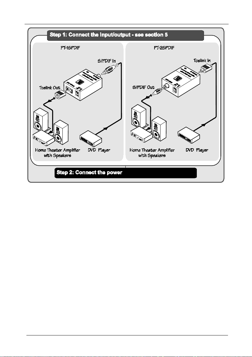
To connect the PT-1SPDIF Digital Audio Converter, as the example in
3 illustrates, do the following
1
:
Figure
1. Connect the digital audio source (for example, the digital audio from a
DVD player) to the S/PDIF IN (coaxial) RCA connector.
2. Connect the OPTICAL TosLink® OUT connector to the digital audio
acceptor (for example, a home theater amplifier).
3. Connect the 12V DC power adapter to the power socket and connect the
adapter to the mains electricity.
Figure 3: Connecting the PT-1SPDIF Digital Audio Converter
1 Switch OFF the power on each device before connectin g it to your PT-1SPDIF. After connecting your PT-1SPDIF, switch
on its power and then switch on the power on each device
5
Page 8

KRAMER: SIMPLE CREATIVE TECHNOLOGY
Connecting the PT -1 SPDIF / PT-2SPDIF
6
5.2 Connecting the PT-2SPDIF Digital Audio Converter
To connect the PT-2SPDIF Digital Audio Converter, as the example in
4 illustrates, do the following
1
:
Figure
1. Connect the digital audio source (for example, the digital audio from a
DVD player) to the OPTICAL TosLink® IN connector.
2. Connect the S/PDIF OUT (coaxial) RCA connector to the digital audio
acceptor (for example, a home theater amplifier).
3. Connect the 12V DC power adapter to the power socket and connect the
adapter to the mains electricity.
Figure 4: Connecting the PT-2SPDIF Digital Audio Converter
1 Switch OFF the power on each device before connectin g it to your PT-2SPDIF. After connecting your PT-2SPDIF, switch
on its power and then switch on the power on each device
Page 9

Technical Specifications
6 Technical Specifications
Table 3 and Table 4 define the technical specifications1:
Table 3: Technical Specifications of the PT-1SPDIF Digital Audio Converter
INPUT: 1 S/PDIF (digital audio) on an RCA connector
OUTPUT: 1 Optical (digital audio) on a Toslink® connector
SAMPLING: 32kHz to 192kHz
POWER SOURCE: 12 VDC 50mA
DIMENSIONS: 4.27cm x 2.2cm x 5.64cm (1.68" x 0.87" 2.22"), W, D, H
WEIGHT: 0.3kg (0.67lbs) approx.
ACCESSORIES: Power supply
OPTIONS: Kramer cables
Table 4: Technical Specifications of the PT-2SPDIF Digital Audio Converter
INPUT: 1 Optical (digital audio) on a Toslink® connector
OUTPUT: 1 S/PDIF (digital audio) on an RCA connector
SAMPLING: 32kHz to 192kHz
POWER SOURCE: 12 VDC 90mA
DIMENSIONS: 4.27cm x 2.2cm x 5.64cm (1.68" x 0.87" 2.22"), W, D, H
WEIGHT: 0.3kg (0.67lbs) approx.
ACCESSORIES: Power supply
OPTIONS: Kramer cables
1 Specifications are subject to change without notice
7
Page 10

KRAMER: SIMPLE CREATIVE TECHNOLOGY
8
LIMITED WARRANTY
WHO IS PROTECTED?
WHAT IS COVERED AND WHA T IS NO T COVERED
WHAT WE WILL P A Y F OR AND WHA T WE WILL N OT P A Y FOR
HOW YOU CAN GET WARRANTY SERVICE
LIMITA TION OF IMPLIED W ARRANTIES
EXCLUSION OF DAMAGES
CAUTION!
Kramer Electronics (hereafter ) warrants this product free from defects in material and workmanship under the
following terms.
Kramer
HOW LONG IS THE WARRANTY
Labor and parts are warranted for seven years from the date of the first customer purchase.
Only the first purchase customer may enforce this warranty.
W e will pa y labor a nd mat erial ex pense s for c overe d items. W e will n ot pay for th e follo wing:
The liab ilit y of K ramer for an y ef fec tive p rod ucts is lim ite d to th e rep air or repl ace ment of the produ ct a t our optio n. Krame r shal l
not be li able for:
This war ranty gives y ou speci fic l egal ri ghts, a nd you m ay also have oth er rig hts, w hich var y from p lace to place.
All produc ts retur ned t o Kramer for ser vice m ust hav e prior a pprov al. Th is may b e obta ined from your deale r.
This equ ipmen t has be en teste d to de termi ne compl iance w ith t he requir emen ts of:
EN-5008 1: "Electr omagne tic co mpatibi lity (EMC);
generic emission standard.
Residen tial, c omme rcial an d light indus try"
EN-5008 2: "Electr omagne tic co mpatibi lity (EMC) gen eric i mmuni ty sta ndard.
Part 1: R esiden tial, comme rcial an d light indus try env ironme nt".
CFR-47: FCC* Rules and Regulations:
Part 15: “Ra d io frequency devices
Subpart B Unintentional radiators”
Except as below, this warranty covers all defects in material or workmanship in this product. The following are not covered
by the warranty:
1. Any product which is not distributed by Kramer, or which is not purchased from an authorized Kramer dealer. If you are
uncertain as to whether a dealer is authorized, please contact Kramer at one of the agents listed in the Web site
www.kramerelectronics.com.
2. Any product, on which the serial number has been defaced, modified or removed, or on which the WARRANTY VOID
T AMP ER E D sti c ke r has be e n to r n,
3. Damage, det eriora tion o r malf unction resu lting f rom:
i) Accident, misuse, abuse, neglect, fire, water, li ghtnin g or oth er acts of nat ure
ii) Product m odifi cation , or fai lure to f ollow instru ction s suppli ed wit h the pr oduc t
iii) Repair o r atte mpted re pair by a nyone not auth oriz ed by Kra mer
iv) Any shipment o f the pr oduct ( claim s must b e pres ented to the carr ier)
v) Removal or inst alla tion of the pro duct
vi) Any other cause, which does not relate to a product defect
vii)Cartons, e quipme nt encl osure s, cabl es or accesso ries use d in c onjunct ion wi th the p roduct
1. Remo val or in stall ations char ges.
2. Costs of initial technical adjustments (set-up), including adjustment of user controls or programming. These costs are the
respon sibili ty of th e Krame r deal er from wh om the produ ct was pu rchas ed.
3. S hippin g char ges.
1. To obtain service on you product, you must take or ship it prepaid to any authorized Kramer service center.
2. Whenever warranty service is required, the original dated invoice (or a copy) must be presented as proof of warranty
coverage, and should be included in any shipment of the product. Please also include in any mailing a contact name,
company, address, and a description of the problem(s).
3. For the name of the nearest Kramer authorized service center, consult your authorized dealer.
All implied warranties, including warranties of merchantability and fitness for a particular purpose, are limited in duration to
the length of this warranty.
1. Da mage to other p roper ty cause d by defe cts in this prod uct, damages based upo n inco nvenie nce, lo ss of use of the pro duct, loss
of time, commercial lo ss; or:
2. An y other da mage s, w het her i nci den tal, co nsequ enti al o r o the rwi se. Some c oun tri es ma y n ot a llow li mita tion s o n ho w lon g a n
implied warranty lasts and/or do not allow the exclusion or limitation of incidental or consequential damages, so the above
limita tions a nd excl usions m ay no t apply to you.
Servicing the machines can only be done by an authorized Kramer technician. Any user who makes changes or
modifications to the unit without the expressed approval of the manufacturer will void user authority to operate the
equipment.
Use the supplie d DC powe r sup ply to f eed pow er to the mach ine.
Please use recommended interconnection cables to connect the machine to other components.
IF reattached, removed or otherwise interfered with.
* FCC and CE appro ved using S TP ca ble (f or twist ed pair pr oducts )
NOTE:
Part 1:
Page 11

For the latest information on our products and a list of Kramer
distributors, visit our Web site: www.kramerelectronics.com,
where updates to this user manual may be found.
We welcome your questions, comments an d feedb a ck.
Safety Warning:
Disconnect the unit from the power supply before
opening/servicing.
Caution
Kramer Electronics, Ltd.
Web site: www.kramerelectronics.com
E-mail: info@kramerel.com
P/N: 2900-000316 REV 2
 Loading...