

Page 1

Kramer Electronics, Ltd.
USER MANUAL
Model:
FC-7501
Analog Video to SDI Converter
Page 2

Contents
Contents
1
Introduction 1
2
Getting Started 1
3
Overview 2
4
Your Analog Video to SDI Converter 3
5
Using Your Analog Video to SDI Converter 4
6
Upgrading the FC-7501 to an FC-7501P 6
6.1 Inserting the 7501M Module 6
7
Technical Specifications 8
8
Communications Protocol for the FC-7501 8
8.1 Description of Instructions 10
Figures
Figure 1: FC-7501 Analog Video to SDI Converter 3
Figure 2: Connecting an FC-7501 Analog Video to SDI Converter 5
Figure 3: Removing the Cover of the FC-7501 6
Figure 4: Upgrading the FC-7501 to FC-7501P by inserting an optional 7501M module 7
Tables
Table 1: Front Panel FC-7501 Analog Video to SDI Converter 3
Table 2: Rear Panel FC-7501 Analog Video to SDI Converter 4
Table 3: Technical specifications of the FC-7501 Analog Video to SDI Converter 8
Table 4: Structure of the Protocol 9
Table 5: Instruction Set for the FC-7501 9
Table 6: Input Standard 10
i
Page 3

Introduction
1 Introduction
Welcome to Kramer Electronics! Since 1981, Kramer Electronics has been
providing a world of unique, creative, and affordable solutions to the vast
range of problems that confront the video, audio, and presentation
professional on a daily basis. In recent years, we have redesigned and
upgraded most of our line, making the best even better! Our 500-plus
different models now appear in eight groups1 that are clearly defined by
function.
Thank you for purchasing your Kramer FC-7501 Analog Video to SDI
Converter, which is ideal for broadcast and production video studios,
postproduction and duplication studios, and non-linear editing.
The package includes the following items:
FC-7501 Analog Video to SDI Converter
Power supply
This user manual2
2 Getting Started
We recommend that you:
Unpack the equipment carefully and save the original box and
packaging materials for possible future shipment
Review the contents of this user manual
Use Kramer high-performance high-resolution cables3
1 GROUP 1: Distribution Amplifiers; GROUP 2: Video and Audio Switchers, Matrix Switchers and Controllers; GROUP 3:
Video, Audio, VGA/XGA Processors; GROUP 4: Interfaces and Sync Processors; GROUP 5: Twisted Pair Interfaces;
GROUP 6: Accessories and Rack Adapters; GROUP 7: Scan Converters and Scalers; and GROUP 8: Cables and Connectors
2 Download up-to-date Kramer user manuals from our Web site at http://www.kramerelectronics.com
3 The complete list of Kramer cables is on our Web site at http://www.kramerelectronics.com
1
Page 4

Overview
3 Overview
The high quality FC-7501 is a multi-standard converter that converts
professional quality video to serial digital video (SDI).
The following analog formats are supported:
Composite video
s-Video
Component video (Y, B-Y, R-Y, sometimes called YUV or Y, Pb,
Pr)
The FC-7501 maintains the high level of professional video quality,
prevalent with component video output devices and DVD players, when
converting to SDI.
The FC-7501 automatically detects the input standard, generating the
appropriate output:
For component video input, 50Hz/625 line (interlaced) and
60Hz/525 line (interlaced) are supported
For YC and CV inputs, all variations of PAL, NTSC and SECAM
are supported
In addition, the FC-7501features:
SDI conversion on 2 buffered and reclocked SDI outputs
Input looping connectors and a 75/Hi-Z input termination switch
An RS-232 port
Control via a user-friendly Windows®-based program that can
modify video parameters such as contrast, saturation and hue,
which may be stored in non-volatile memory
True 10-bit digitizing - ideal for broadcast applications
To achieve the best performance:
Use only good quality connection cables1 to avoid interference,
deterioration in signal quality due to poor matching, and elevated
noise levels (often associated with low quality cables).
Avoid interference from neighboring electrical appliances that
may adversely influence signal quality and position your Kramer
FC-7501 in a location free from moisture and away from
excessive sunlight and dust
1 Available from Kramer Electronics on our Web site at http://www.kramerelectronics.com
2
KRAMER: SIMPLE CREATIVE TECHNOLOGY
Page 5
Your Analog Video to SDI Converter
Caution – No operator-serviceable parts inside unit.
Warning – Use only the Kramer Electronics input power
wall adapter that is provided with this unit1.
Warning – Disconnect power and unplug unit from wall
before installing or removing device or servicing unit.
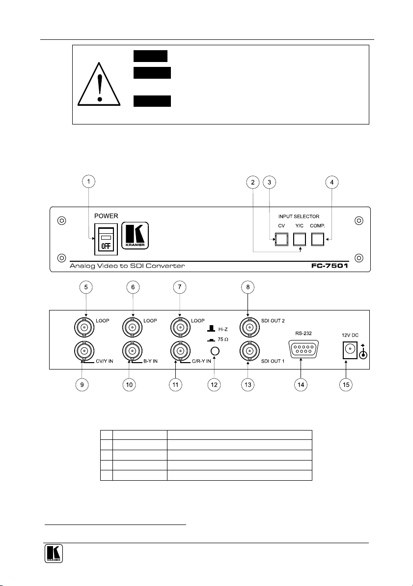
4 Your Analog Video to SDI Converter
Figure 1, Table 1, and Table 2, define the FC-7501:
Figure 1: FC-7501 Analog Video to SDI Converter
Table 1: Front Panel FC-7501 Analog Video to SDI Converter
# Feature Function
1 POWER Switch Illuminated switch supplying power to the unit
2 Y/C Button Press to select the s-Video (Y/C) source
3 CV Button Press to select the composite video source
4 COMP. Button Press to select the component source
1 For example: model number AD2512C, part number 2535-000251
3
Page 6

Using Your Analog Video to SDI Converter
Table 2: Rear Panel FC-7501 Analog Video to SDI Converter
# Feature Function
5 CV/Y LOOP BNC Connector Connects to the composite, s-Video1 or component2 video loop
6 B-Y LOOP BNC Connector Connects to the component2 video loop
7 C/R-Y LOOP BNC Connector Connects to the s-Video1 or component2 video loop
8 SDI OUT 2 BNC Connector Connects to the serial digital video acceptor 2
9 CV/Y IN BNC Connector Connects to the composite, s-Video1 or component2 video source
10 B-Y IN BNC Connector Connects to the component2 video source
11 C/R-Y IN BNC Connector Connects to the s-Video1 or component2 video source
12
Hi-Z / 75 Button Press to terminate at 75 or release for looping3
13 SDI OUT 1 BNC Connector Connects to the serial digital video acceptor 1
14 RS-232 Port Connects to the PC or the Remote Controller
15 12V DC Power Connector VDC, 320mA
5 Using Your Analog Video to SDI Converter
You can use your FC-7501, to convert professional quality composite
video, s-Video or component video (as the example in Figure 2 illustrates)
to one or two SDI video outputs.
To convert component video to two SDI video outputs, do the following:
1. Connect a component video source (for example, a Betacam component
VCR) to the component video BNC input connectors, Y, B-Y, and R-Y.
2. Connect both SDI outputs to SDI acceptors as follows (when only one SDI
output is required, use either of the SDI outputs of the FC-7501, and leave
the other SDI output unconnected):
Connect the SDI OUT 1 BNC connector to an SDI acceptor
(for example, a Non-Linear Editor)
Connect the SDI OUT 2 BNC connector to the second SDI
acceptor (for example, an SDI monitor)
3. Connect the component video loop connectors, LOOP Y, LOOP B-Y,
and LOOP R-Y, to a component monitor, and release the Hi-Z/75
button to Hi-Z (optional).
When the inputs are not looped, the Hi-Z/75 button should be pressed
4. Connect the 12V DC power adapter to the power socket and connect the
adapter to the mains electricity.
1 For s-Video, connect the CV/Y and the C/R-Y connectors
2 For component video, connect all 3 connectors: Y, B-Y, and R-Y
3 Push in to terminate the input. Release when the input extends to another unit
4
KRAMER: SIMPLE CREATIVE TECHNOLOGY
Page 7

Using Your Analog Video to SDI Converter
5. Turn on the power and press the COMP. (Component video) button.
The component video signal converts to SDI at both SDI OUT 1 and SDI
OUT 2.
Figure 2: Connecting an FC-7501 Analog Video to SDI Converter
5
Page 8

Upgrading the FC-7501 to an FC-7501P
6 Upgrading the FC-7501 to an FC-7501P
You can improve the SDI Pixel Jitter by converting the FC-7501 to an
FC-7501P (an Analog Video to SDI Converter with very low jitter), as
explained in the following steps.
6.1 Inserting the 7501M Module
1. Unfasten the two pairs of screws on each side of the cover of the FC-7501
and remove the cover, as Figure 3 illustrates:
Figure 3: Removing the Cover of the FC-7501
2. Remove jumpers on J7 and J8 (see Figure 4.)
3. Insert the optional 7501M module (“PLL board”) onto the two sets of 16
pins, and secure it to the spacer by fastening the washer and screw1, as
shown in Figure 4.
1 Supplied with the 7501M optional module
6
KRAMER: SIMPLE CREATIVE TECHNOLOGY
Page 9

Upgrading the FC-7501 to an FC-7501P
Figure 4: Upgrading the FC-7501 to FC-7501P by inserting an optional 7501M module
4. Replace the cover on the FC-7501, and secure it in place by fastening the
two pairs of screws on each side of the cover.
The FC-7501P is an upgraded FC-7501 unit (with the 7501M added).
7
Page 10

Technical Specifications
7 Technical Specifications
Table 3 includes the technical specifications:
Table 3: Technical specifications1 of the FC-7501 Analog Video to SDI Converter
INPUTS:
VIDEO STANDARDS:
OUTPUTS: 2 SDI on BNC connectors
BANDWIDTH: 0.2dB to 5MHz; 1dB to 6MHz
LUMINANCE
NON-LINERARITY:
K-FACTOR: 0.1%
S/N RATIO: 57dB (worst case)
CHROMA/LUMA
DELAY:
SDI PIXEL JITTER: <500ps (10Hz HPF) with PLL option board
INPUT COUPLING: DC or AC via internal jumpers
POWER SOURCE: 12 VDC, 320mA
DIMENSIONS: 22cm x 18cm x 4.5cm (8.7" x 7" x 1.7") W, D, H.
WEIGHT: 1.3 kg (2.9 lbs.) approx.
ACCESSORIES: Power supply
OPTIONS: 19” rack adapter RK-80
1 composite
video/Y:
1 (B-Y):
1 (R-Y)/C:
CV, YC: NTSC (M, Japan, 4.43), PAL (B, D, G, H, I, M, N, Nc) and
Component: 50 Hz/625 line, 60 Hz/525 line
1% (worst case)
<10ns
<1ns (10kHz HPF) without PLL option board
1Vpp/75 looping on BNC connectors with a termination switch
0.7Vpp/75 looping on BNC connectors with a termination
switch
0.7Vpp/0.3Vpp/75 looping on BNC connectors with a
termination switch
SECAM (B, D, G, K, K1, L)
8 Communications Protocol for the FC-75012
RS-232 communication with the FC-7501 complies with the following
protocol. The protocol uses 4 bytes of information, and data is at 9600 baud,
with no parity, 8 data bits and 1 stop bit. A null-modem RS-232 connection
should be used between the PC (or other controller) and the FC-7501. That
is, for a DB-9 port, connect as follows:
Connect pin 5 of the PC to pin 5 of the machine
Cross pins 2 and 3, ie. connect pin 2 of the PC to pin 3 of the
machine, and connect pin 3 of the PC to pin 2 of the machine
On the PC side, short pins 4 and 6
On the PC side, short pins 1, 7 and 8.
1 Specifications are subject to change without notice
2 VER-0.3, 20/01/03. Download the Communication Protocol FC-7501 from our Web site at http://www.kramerelectronics.com
8
KRAMER: SIMPLE CREATIVE TECHNOLOGY
Page 11

Communications Protocol for the FC-7501
This protocol complements Kramer’s “Protocol 2000” (Kramer’s switcher
protocol), so the two protocols can co-exist without disturbing one another.
(According to Protocol 2000, the FC-7501 appears as machine number 22,
so care should be taken not to set a switcher with this machine number).
Table 4: Structure of the Protocol
MSB
0 TO PC I5 I4 I3 I2 I1 I0
7 6 5 4 3 2 1 0
1st byte
1 D6 D5 D4 D3 D2 D1 D0
7 6 5 4 3 2 1 0
2nd byte
EXTENDED DATA
1 E6 E5 E4 E3 E2 E1 E0
7 6 5 4 3 2 1 0
3rd byte
1 E7 D7 1 0 1 1 0
7 6 5 4 3 2 1 0
4th byte1
Note that the MSB’s of the DATA (D7) and the EXTENDED DATA (E7) are in the fourth byte.
Terminology:
The destination bit, TO PC, is 0 when sending from the PC to the machine, or 1 when sending from the machine to the PC.
INSTRUCTION
DATA
MSB’s
TO PC is the “DESTINATION BIT”
I4..I0 is the “INSTRUCTION”
D7..D0 is the “DATA”
E7..E0 is the “EXTENDED DATA”
A0 is the “LSB of the MACHINE ADDRESS”
Table 5: Instruction Set for the FC-7501
# INSTRUCTION
0 Reset 0 0 0 0 0 0
1 Read video standard 0 0 0 0 0 1
2 Write video standard 0 0 0 0 1 0
3 Read front-panel switch (video format) 0 0 0 0 1 1
4 Press front-panel switch (video format) 0 0 0 1 0 0
5 Read video field rate 0 0 0 1 0 1
6 Force video standard 0 0 0 1 1 0
10 Write EEPROM data – low address 0 0 1 0 1 0
11 Read EEPROM data – low address 0 0 1 0 1 1
12 Write I²C 0 0 1 1 0 0
13 Read I²C 0 0 1 1 0 1
16 Error 0 1 0 0 0 0
20 Write EEPROM data – high address 0 1 0 1 0 0
21 Read EEPROM data – high address 0 1 0 1 0 1
57 Enable “Power-down save” 1 1 1 0 0 1
61 Identify machine 1 1 1 1 0 1
I5 I4 I3 I2 I1 I0
LSB
ADDR
1 Note that the MSB’s of the DATA (D7) and the EXTENDED DATA (E7) are in the fourth byte
9
Page 12

Communications Protocol for the FC-7501
8.1 Description of Instructions
INSTRUCTION 0 – RESET
DATA=0: initialize the machine.
When the machine is initialized, it will send the RESET code (DATA = 0). If the machine receives this code, it will reset to
its “power-up” state.
DATA=1: configure the machine to its factory default state.
When the machine receives this code, all programmable parameters will be reset to their factory-default values.
EXTENDED DATA - set as 0.
INSTRUCTION 1 – READ INPUT STANDARD
For sending to machine, set DATA = EXTENDED DATA = 0.
When replying:- DATA = INPUT STANDARD; EXTENDED DATA = 0.
The PC sends this instruction to the machine. The machine replies by sending back the INPUT STANDARD, defined as per
the table below:
Table 6: Input Standard
STANDARD E2 E1 E0
NTSC (J, M) 0 0 0
PAL (B, G, H, I, N) 0 0 1
PAL-M 0 1 0
Combination PAL-N 0 1 1
NTSC 4.43 1 0 0
INSTRUCTION 2 – WRITE VIDEO STANDARD
DATA = set as video standard (see table above). This is valid for CV and Y/C formats.
The PC sends the video standard to the machine. The standard is implemented, and the machine replies by sending the same
data back to the PC.
Note that the machine should be set for “forced video standard” (instruction #6) if using this instruction, (since the unit will
otherwise detect - and revert back to - the standard of the current video input).
INSTRUCTION 3 – READ FRONT-PANEL SWITCH (read format)
When sending to machine:- DATA, EXTENDED DATA - set as 0.
When replying:- DATA = front-panel switch number (0=CV, 1=Y/C, 2=Component).; EXTENDED DATA = 0.
The PC sends this instruction to the machine. The machine replies by sending back a value relating to the current video
format.
INSTRUCTION 4 – PRESS FRONT-PANEL SWITCH (select format)
DATA = front-panel switch number (0=CV, 1=Y/C, 2=Component).
EXTENDED DATA - set as 0.
- When the machine receives this instruction, it selects the new video format – as is done if the front-panel switch was
pressed. If this results in a change in the video format, then the unit replies by sending the same data back to the PC.
INSTRUCTION 5 – READ FIELD RATE
When sending to machine:- DATA, EXTENDED DATA - set as 0.
When replying:- DATA=0 for 60Hz field rate; DATA=1 for 50Hz field rate; EXTENDED DATA=0.
The PC sends this instruction to the machine. The machine replies by sending back a value relating to the current video field
rate.
INSTRUCTION 6 – FORCE VIDEO STANDARD
DATA = 0 to allow the unit to automatically detect and decode the input standard; DATA = 1 to force the unit to decode a
video standard (see instruction #2). This instruction is valid for CV and Y/C formats.
The PC sends the data to the machine, and the machine replies by sending the same data back to the PC.
INSTRUCTION 10 & 20 – WRITE EEPROM DATA
DATA = EEPROM sub-address; EXTENDED DATA = data to be written to this sub-address.
The PC sends data directly to the EEPROM. The EEPROM stores this new value, and replies by sending the same data back
to the PC.
CAUTION – this function was designated for development and testing purposes. Improper use of this function may cause
erratic behaviour of the machine.
INSTRUCTION 11 & 21 – READ EEPROM DATA
For sending to machine, DATA = EEPROM sub-address.
When replying:- DATA = EEPROM sub-address; EXTENDED DATA = requested data.
The PC sends this instruction to the machine. The machine replies by sending back the data of this sub-address.
10
KRAMER: SIMPLE CREATIVE TECHNOLOGY
Page 13

Communications Protocol for the FC-7501
INSTRUCTION 12 – WRITE I²C
DATA = I²C sub-address; EXTENDED DATA = data to be written to this sub-address.
The PC sends I²C data (to the I²C address which was last accessed via INSTRUCTION 13). The machine replies by sending
the same data back to the PC.
CAUTION – this function was designated for development and testing purposes. Improper use of this function may cause
erratic behavior of the machine.
INSTRUCTION 13 – READ I²C
For sending to machine, DATA = I²C address; EXTENDED DATA = sub-address.
When replying:- DATA = sub-address; EXTENDED DATA = data read.
The PC sends this instruction to the machine. The machine replies by sending back the data of this address and sub-address.
INSTRUCTION 16 – ERROR
If the machine receives an invalid instruction, it replies by sending this error code.
INSTRUCTION 57 – ENABLE “POWER-DOWN SAVE”
DATA = 0 disables power-down saving; DATA = 1 enables saving. EXTENDED DATA - set to 0.
The PC sends this instruction to the machine. The power-down option is enabled or disabled according to the value of DATA.
If the power-down option is enabled, then the machine will “remember” its state before being turned off, and revert to this
state when turned on again.
Note that whenever the machine is turned on, the power-down save option is enabled.
INSTRUCTION 61 – IDENTIFY MACHINE
For sending, DATA = 1 to request machine name; DATA = 3 to request software version number. EXTENDED DATA - set
to 0.
The PC sends this instruction to the machine. The machine relies as follows:
if the machine name is requested, the machine replies with DATA = 75 (hex), and EXTENDED DATA = 01 (hex).
if the software version is requested, the machine replies with DATA as the version number before the decimal point, and
EXTENDED DATA is the value following the decimal point. For example, for version 3.4, the machine replies with DATA =
03 (hex), and EXTENDED DATA = 04 (hex).
11
Page 14

12
KRAMER: SIMPLE CREATIVE TECHNOLOGY
Page 15

For the latest information on our products and a list of Kramer
distributors, visit our Web site: www.kramerelectronics.com
where updates to this user manual may be found.
We welcome your questions, comments and feedback.
Safety Warning:
Disconnect the unit from the power supply before
opening/servicing.
Caution
Kramer Electronics, Ltd.
Web site: www.kramerelectronics.com
E-mail: info@kramerel.com
P/N: 2900-004016 REV 2
 Loading...