

Page 1

KRAMER ELECTRONIC S LTD.
USER MANUAL
MODELS:
FC-21ETH, FC-22ETH and
FC-24ETH
Ethernet Controller
P/N: 2900-300221 Rev 1
Page 2
Page 3

FC-21ETH – Contents
i
Contents
1 Introduction 1
2 Getting Started 2
2.1 Achieving the Best Performance 2
2.2 Safety Instructions 2
2.3 Recycling Kramer Products 3
3 Overview 4
4 Defining the FC-21ETH, FC-22ETH and FC-24ETH Ethernet Controllers 6
4.1 Defining the FC-21ETH Ethernet Controller 6
4.2 Defining the FC-22ETH Ethernet Controller 8
4.3 Defining the FC-24ETH Ethernet Controller 10
5 Initial Configuration and Use Overview 12
5.1 Configuring the FC-21ETH, FC-22ETH and FC-24ETH 12
5.2 Configuring a Virtual Port on the PC 14
5.3 Configuring an Ethernet Connection on the PC 14
6 Connecting the FC-21ETH, FC-22ETH and FC-24ETH 15
6.1 Connecting via Ethernet 17
6.2 Connecting to the Ethernet Controller via RS-232 21
6.3 Connecting to a Controlled Device via the RS-485 Port 21
7 Operating the FC-21ETH, FC-22ETH and FC-24ETH Remotely via the Web
Pages 23
7.1 Browsing the FC-24ETH Web Pages 23
7.2 Connected Clients Page 25
7.3 Device Settings Page 26
7.4 Communication Page 27
7.5 Serial Port Settings Page 28
7.6 Security Page 29
7.7 Logs Page 31
7.8 About Us Page 32
8 Configuring and Maintaining the FC-21ETH, FC-22ETH and FC-24ETH 33
8.1 Selecting the RS-232 or RS-485 Serial Port 33
8.2 Terminating the RS-485 Bus 33
8.3 Activating DHCP 34
8.4 Resetting to the Factory Default Settings 34
8.5 Upgrading the Firmware 34
9 Technical Specifications 35
9.1 Data Handling Performance 35
9.2 Example Bandwidth Calculation 36
10 Default Communication Parameters 37
11 Kramer Protocol 3000 38
11.1 Kramer Protocol 3000 Syntax 38
11.2 Kramer Protocol 3000 Commands 40
Page 4

ii
FC-21ETH - Contents
Figures
Figure 1: FC-21ETH Ethernet Controller Front Panel 6
Figure 2: FC-21ETH Ethernet Controller Rear Panel 7
Figure 3: FC-22ETH Ethernet Controller Front Panel 8
Figure 4: FC-22ETH Ethernet Controller Rear Panel 9
Figure 5: FC-24ETH Ethernet Controller Front Panel 10
Figure 6: FC-24ETH Ethernet Controller Rear Panel 11
Figure 7: Connecting the FC-24ETH for Initial Configuration 12
Figure 8: Configuring a Remote Connection 14
Figure 9: Connecting the FC-24ETH Ethernet Controller 16
Figure 10: Local Area Connection Properties Window 18
Figure 11: Internet Protocol Version 4 Properties Window 19
Figure 12: Internet Protocol Version 6 Properties Window 19
Figure 13: Internet Protocol Properties Window 20
Figure 14: General Info Page 24
Figure 15: Connected Clients Page 25
Figure 16: Device Settings Page 26
Figure 17: Communication Page 27
Figure 18: Serial Port Settings Page 28
Figure 19: Security Page 29
Figure 20: Security Confirmation Popup 29
Figure 21: Authentication Required Popup 30
Figure 22: Security Activated Page 30
Figure 23: Logs Page 31
Figure 24: About Us Page 32
Page 5

Introduction
1
1 Introduction
Welcome to Kramer Electronics! Since 1981, Kramer Electronics has been
providing a world of unique, creative, and affordable solutions to the vast range of
problems that confront video, audio, presentation, and broadcasting professionals
on a daily basis. In recent years, we have redesigned and upgraded most of our
line, making the best even better!
Our 1,000-plus different models now appear in 11 groups that are clearly defined
by function: GROUP 1: Distribution Amplifiers; GROUP 2: Switchers and Routers;
GROUP 3: Control Systems; GROUP 4: Format/Standards Converters; GROUP 5:
Range Extenders and Repeaters; GROUP 6: Specialty AV Products; GROUP 7:
Scan Converters and Scalers; GROUP 8: Cables and Connectors; GROUP 9:
Room Connectivity; GROUP 10: Accessories and Rack Adapters and GROUP 11:
Sierra Products.
Congratulations on purchasing your Kramer FC-21ETH, FC-22ETH or
FC-24ETH Ethernet Controller, which is ideal for the following typical applications:
Use with Ethernet/RS-232 interfaces and/or Ethernet/RS-485 interfaces
Page 6

2
Getting Started
Go to http://www.kramerelectronics.com/support/product_downloads.asp
to check for up-to-date user manuals, application programs, and to check if
firmware upgrades are available (where appropriate).
This equipment is to be used only inside a building. It may only be
connected to other equipment that is installed inside a building.
Caution:
There are no operator serviceable parts inside the unit
Warning:
Use only the Kramer Electronics input power wall
adapter that is provided with the unit.
Warning:
Disconnect the power and unplug the unit from the wall
before installing
i
!
!
2 Getting Started
We recommend that you:
Unpack the equipment carefully and save the original box and packaging
materials for possible future shipment
Review the contents of this user manual
Use Kramer high performance high resolution cables
2.1 Achieving the Best Performance
To achieve the best performance:
Use only good quality connection cables (we recommend Kramer high-
performance, high-resolution cables) to avoid interference, deterioration in
signal quality due to poor matching, and elevated noise levels (often
associated with low quality cables)Do not secure the cables in tight bundles
or roll the slack into tight coils
Avoid interference from neighboring electrical appliances that may adversely
influence signal quality
Position your Kramer FC-21ETH, FC-22ETH and FC-24ETH away from
moisture, excessive sunlight and dust
2.2 Safety Instructions
Page 7

Getting Started
3
2.3 Recycling Kramer Products
The Waste Electrical and Electronic Equipment (WEEE) Directive 2002/96/EC
aims to reduce the amount of WEEE sent for disposal to landfill or incineration by
requiring it to be collected and recycled. To comply with the WEEE Directive,
Kramer Electronics has made arrangements with the European Advanced
Recycling Network (EARN) and will cover any costs of treatment, recycling and
recovery of waste Kramer Electronics branded equipment on arrival at the EARN
facility. For details of Kramer’s recycling arrangements in your particular country
go to our recycling pages at http://www.kramerelectronics.com/support/recycling/.
Page 8

4
Overview
3 Overview
The FC-21ETH, FC-22ETH and FC-24ETH are a family of high-performance,
easy-to-use, bidirectional hardware and software interface systems for controlling
RS-232 and/or RS-485 controllable machines via an Ethernet LAN, as well as via
the Internet.
These Ethernet to serial controllers bridge the gap between Ethernet
infrastructures and serial communication devices by offering bidirectional Ethernet
to serial conversion. All setup and maintenance of the devices is done from built-in
Web pages which are accessible using any common Web browser. All devices
offer one RS-232/RS-485 dual-use serial port.
In particular, the FC-21ETH, FC-22ETH and FC-24ETH:
Offer network connectivity that lets you connect a Kramer (or other) device
via its RS-232 or RS-485 port to an Ethernet LAN
Let you control up to three RS-232 devices and one RS-485 device (model
dependent) via Ethernet from a PC
Let you control a device from multiple Ethernet points (PCs or remote
controllers), via a LAN or the Internet
Include Windows® based Virtual Port software for setting up virtual ports on
a PC
Support Internet-based, remote firmware upgrades
Can be rack mounted in a 1U rack space with the optional rack adapters
More specifically, the FC-21ETH, FC-22ETH and FC-24ETH feature:
One RS-232/RS-485 port (FC-21ETH), one RS-232 and one RS-232/RS-
485 port (FC-22ETH), three RS-232 and one RS-232/RS-485 ports
(FC-24ETH)
An Ethernet LAN connection
Static or dynamic (DHCP) IP addressing
A USB port for upgrading the firmware
Page 9

Overview
5
A 5V DC power supply
A compact Kramer TOOLS™ enclosure (FC-21ETH, FC-22ETH) or
MegaTOOLS™ enclosure (FC-24ETH) which can be mounted side by side
in a 19-inch rack using suitable rack adapters
The FC-21ETH, FC-22ETH and FC-24ETH include the Virtual Serial Port Manager
(Kramer VSPM) for compatibility with applications based on COM-port
communication. The virtual serial port:
Makes the FC-21ETH, FC-22ETH and FC-24ETH compatible with all
Windows®-based applications which require a physical COM port. This
includes all versions of K-Router and other Kramer control applications. It
lets you operate all RS-232 and RS-485 controllable devices via an Ethernet
LAN using their existing PC software
Operates like a physical COM port, that is, a logical COM port that behaves
like a standard hardware COM port. In reality, it transparently reroutes the
data using the TCP/IP network to the FC-21ETH, FC-22ETH or FC-24ETH
interface via a virtual connection which you can emulate over the Ethernet or
Internet
Can be created in any quantity on your PC and does not occupy a physical
serial port
Page 10
6
Defining the FC-21ETH, FC-22ETH and
FC-24ETH Ethernet Controllers
#
Feature
Function
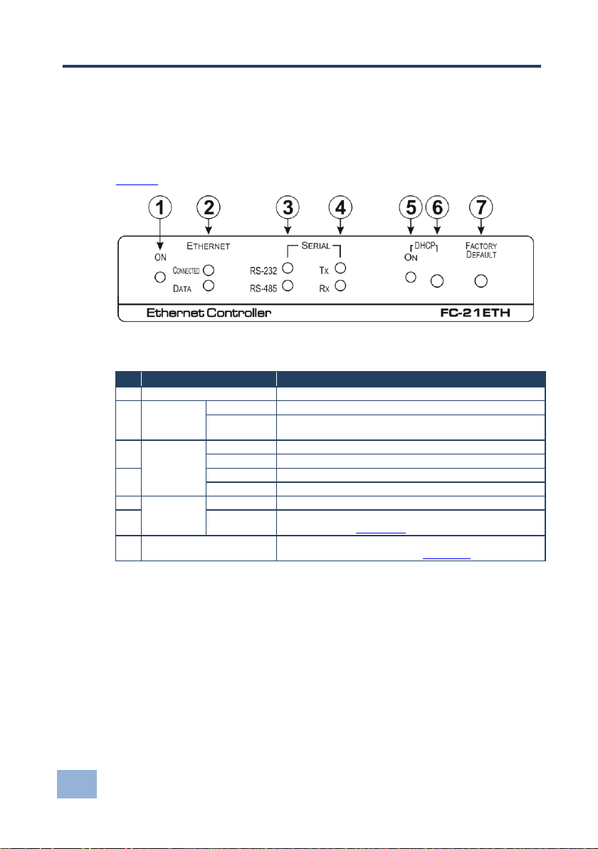
1
ON LED
Lights green when the unit is on
2
ETHERNET
LEDs
CONNECTED
Lights yellow when the Ethernet port is connected
DATA
Flashes green when data is transferred over the Ethernet
link
3
SERIAL
LEDs
RS-232
Lights green when RS-232 is selected
RS-485
Lights green when RS-485 is selected
4
Tx
Flashes red when the serial port is transmitting data
Rx
Flashes green when the serial port is receiving data
5
DHCP
ON LED
Lights green when DHCP is selected
6
Button
Press to toggle the selection between DHCP and static IP
addressing, (see Section 8.3)
7
FACTORY DEFAULT Button
Press and hold while power-cycling the device to reset to
factory default parameters, (see Section 10)
4 Defining the FC-21ETH, FC-22ETH and
FC-24ETH Ethernet Controllers
4.1 Defining the FC-21ETH Ethernet Controller
Figure 1 defines the front panel of the FC-21ETH.
Figure 1: FC-21ETH Ethernet Controller Front Panel
Page 11
Defining the FC-21ETH, FC-22ETH and
FC-24ETH Ethernet Controllers
7
#
Feature
Function
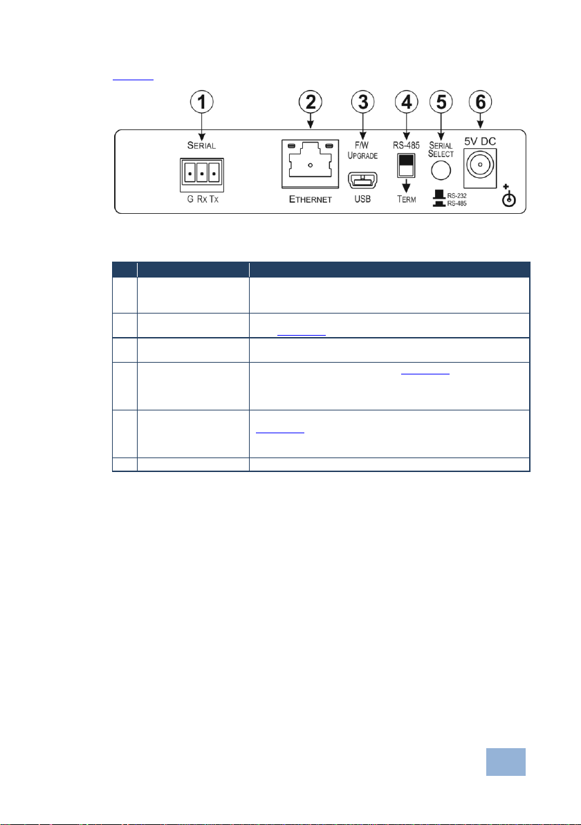
1
SERIAL 3-pin
Terminal Block
Connect to an RS-232 or RS-485 controlled device.
When connecting as an RS-485 port, the connections are G,
B, A in place of G, Rx, Tx
2
ETHERNET RJ-45
Connector
Connect to the PC or other controller directly or via a LAN
(see Section 6.1)
3
F/W UPGRADE USB
Connector
Connect to a PC to upgrade the firmware
4
RS-485 TERM Switch
Terminates the RS-485 bus, (see Section 8.3).
Slide down when this is the last device on an RS-485 bus.
Slide up when this device is not the last device on an RS-485
bus
5
SERIAL SELECT
Button
Selects either RS-232 or RS-485 serial communication, (see
Section 8.3).
Depress for RS-485 serial communication.
Release for RS-232 serial communication
6
5V DC Connector
Connect to the 5V DC power supply, center pin positive
Figure 2 defines the rear panel of the FC-21ETH.
Figure 2: FC-21ETH Ethernet Controller Rear Panel
Page 12
8
Defining the FC-21ETH, FC-22ETH and
FC-24ETH Ethernet Controllers
#
Feature
Function
1
ON LED
Lights green when the unit is on
2
ETHERNET
LEDs
CONNECTED
Lights yellow when the Ethernet port is connected
DATA
Flashes green when data is transferred over the
Ethernet link
3
SERIAL 1
LEDs
RS-232
Lights green when RS-232 is selected
RS-485
Lights green when RS-485 is selected
4
SERIAL I/Os
1 LEDs
Tx
Flashes red when the device is transmitting data over
serial port 1
Rx
Flashes green when the device is receiving data on
serial port 1
5
SERIAL I/Os
2 LEDs
Tx
Flashes red when the device is transmitting data over
serial port 2
Rx
Flashes green when the device is receiving data on
serial port 2
6
DHCP
ON LED
Lights green when DHCP is selected
7
Button
Selects either DHCP or static IP addressing, (see
Section 8.3).
Press to toggle the selection between DHCP and
static IP addressing
8
FACTORY DEFAULT Button
Press and hold while power-cycling the device to
reset to factory default parameters, (see Section 10)
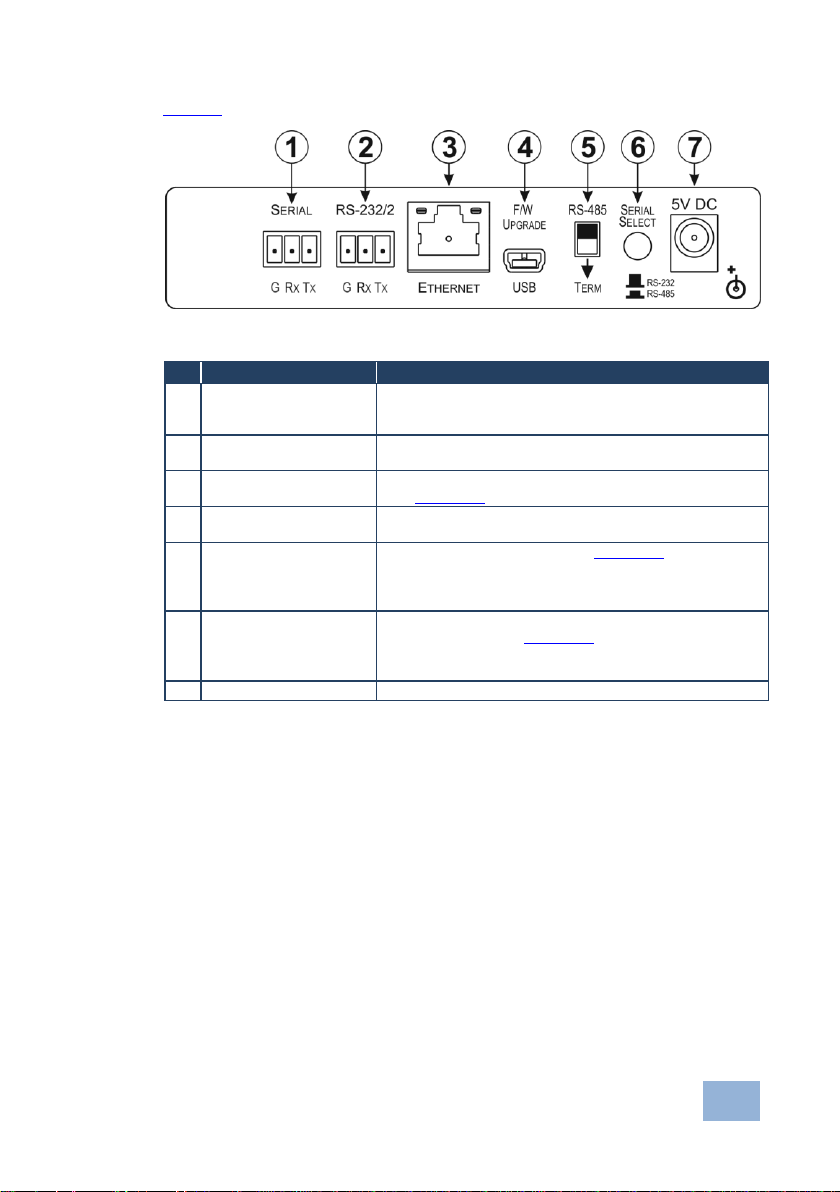
4.2 Defining the FC-22ETH Ethernet Controller
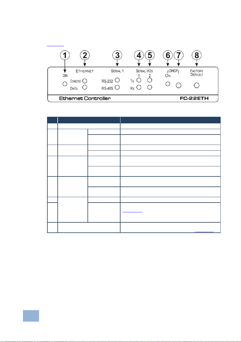
Figure 3 defines the front panel of the FC-22ETH.
Figure 3: FC-22ETH Ethernet Controller Front Panel
Page 13
Defining the FC-21ETH, FC-22ETH and
FC-24ETH Ethernet Controllers
9
#
Feature
Function
1
SERIAL 3-pin Terminal
Block
Connect to an RS-232 or RS-485 controlled device.
When connecting as an RS-485 port, the connections are G,
B, A in place of G, Rx, Tx
2
RS-232/2 3-pin Terminal
Block
Connect to an RS-232 controlled device
3
ETHERNET RJ-45
Connector
Connect to the PC or other controller directly or via a LAN
(see Section 6.1)
4
F/W UPGRADE USB
Connector
Connect to a PC to upgrade the firmware
5
RS-485 TERM Switch
Terminates the RS-485 bus, (see Section 8.3).
Slide down when this is the last device on an RS-485 bus.
Slide up when this device is not the last device on an
RS-485 bus
6
SERIAL SELECT Button
Selects either RS-232 or RS-485 serial communication for
the SERIAL port, (see Section 8.3).
Depress for RS-485 serial communication.
Release for RS-232 serial communication
7
5V DC Connector
Connect to the 5V DC power supply, center pin positive
Figure 4 defines the rear panel of the FC-22ETH.
Figure 4: FC-22ETH Ethernet Controller Rear Panel
Page 14
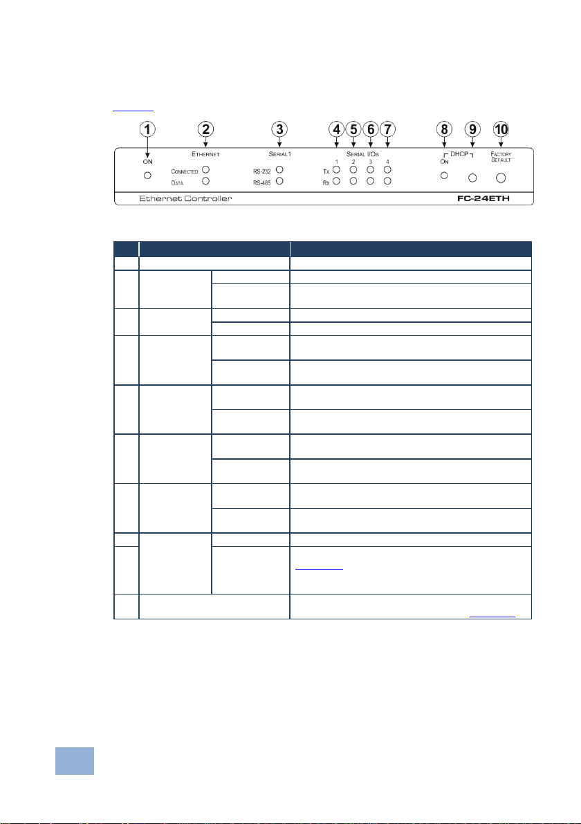
10
Defining the FC-21ETH, FC-22ETH and
FC-24ETH Ethernet Controllers
#
Feature
Function
1
ON LED
Lights green when the unit is on
2
ETHERNET
LEDs
CONNECTED
Lights yellow when the Ethernet port is connected
DATA
Flashes green when data is transferred over the
Ethernet link
3
SERIAL 1
LEDs
RS-232
Lights green when RS-232 is selected
RS-485
Lights green when RS-485 is selected
4
SERIAL I/Os
1 LEDs
Tx
Flashes red when the device is transmitting data over
serial port 1
Rx
Flashes green when the device is receiving data on
serial port 1
5
SERIAL I/Os
2 LEDs
Tx
Flashes red when the device is transmitting data over
serial port 2
Rx
Flashes green when the device is receiving data on
serial port 2
6
SERIAL I/Os
3 LEDs
Tx
Flashes red when the device is transmitting data over
serial port 3
Rx
Flashes green when the device is receiving data on
serial port 3
7
SERIAL I/Os
4 LEDs
Tx
Flashes red when the device is transmitting data over
serial port 4
Rx
Flashes green when the device is receiving data on
serial port 4
8
DHCP
ON LED
Lights green when DHCP is selected
9
Button
Selects either DHCP or static IP addressing, (see
Section 8.3).
Press to toggle the selection between DHCP and
static IP addressing
10
FACTORY DEFAULT Button
Press and hold while power-cycling the device to
reset to factory default parameters, (see Section 10)
4.3 Defining the FC-24ETH Ethernet Controller
Figure 5 defines the front panel of the FC-24ETH.
Figure 5: FC-24ETH Ethernet Controller Front Panel
Page 15
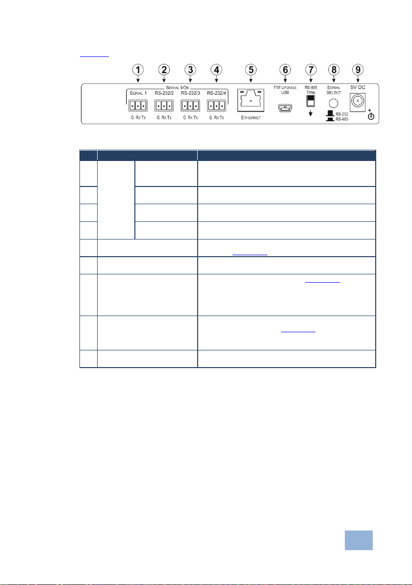
Defining the FC-21ETH, FC-22ETH and
FC-24ETH Ethernet Controllers
11
#
Feature
Function
1
SERIAL
I/Os
SERIAL 3-pin
Terminal Block
Connect to an RS-232 or RS-485 controlled device.
When connecting as an RS-485 port, the connections
are G, B, A in place of G, Rx, Tx
2
RS-232/2 3-pin
Terminal Block
Connect to an RS-232 controlled device
3
RS-232/2 3-pin
Terminal Block
Connect to an RS-232 controlled device
4
RS-232/2 3-pin
Terminal Block
Connect to an RS-232 controlled device
5
ETHERNET RJ-45
Connector
Connect to the PC or other controller directly or via a
LAN (see Section 6.1)
6
F/W UPGRADE USB
Connector
Connect to a PC to upgrade the firmware
7
RS-485 TERM Switch
Terminates the RS-485 bus, (see Section 8.3).
Slide down when this is the last device on an RS-485
bus.
Slide up when this device is not the last device on an
RS-485 bus
8
SERIAL SELECT Button
Selects either RS-232 or RS-485 serial communication
for the SERIAL port, (see Section 8.3).
Depress for RS-485 serial communication.
Release for RS-232 serial communication
9
5V DC Connector
Connect to the 5V DC power supply, center pin
positive
Figure 6 defines the rear panel of the FC-24ETH.
Figure 6: FC-24ETH Ethernet Controller Rear Panel
Page 16

12
Initial Configuration and Use Overview
5 Initial Configuration and Use Overview
This chapter provides an overview of the initial configuration and basic operation
of the FC-21ETH, FC-22ETH and FC-24ETH. The chapter comprises:
Configuring the FC-21ETH, FC-22ETH and FC-24ETH (see Section 5.1)
Configuring a virtual port on the PC (see Section 5.2)
Configuring an Ethernet connection on the PC (see Section 5.3)
In the following description the FC-24ETH is used as an example. The same
principles apply to the FC-21ETH and FC-22ETH.
Figure 7: Connecting the FC-24ETH for Initial Configuration
5.1 Configuring the FC-21ETH, FC-22ETH and FC-24ETH
To configure the FC-21ETH, FC-22ETH and FC-24ETH:
1. Connect the Ethernet port on the rear panel of the FC-21ETH, FC-22ETH
and FC-24ETH to a PC either directly or via a LAN, (see Section 6.1).
Page 17

Initial Configuration and Use Overview
13
2. Using a Web browser, (see Section 6.1 and Section 7) browse to the
General Info home page (see Figure 14).
3. Click on Device Settings to browse to the Device Settings page, (see
Figure 16).
4. Enter the time and date manually, or enter the Time server address for
automatic time and date synchronization.
5. Click Save Changes.
6. Click on Communication to browse to the Communication page, (see
Figure 17).
7. Enter the IP address, mask and gateway for static IP addressing and Click
Set.
—Or—
Click DHCP On for dynamic IP addressing.
Note: If you have changed the IP from the default setting, you must reload
the General Info home page again using the new IP address.
8. Click on Serial Ports Settings to browse to the Serial Port Settings page,
(see Figure 18).
9. Associate the required serial ports with their corresponding TCP/UDP
settings.
10. For each associated serial port, enter the serial port configuration
parameters using the drop-down lists under Serial Configuration.
11. Click Save Changes.
12. If required, click on Security to browse to the Security page.
13. Click ON to activate security.
The user name and password credentials popup appears.
14. Enter the required user name and password.
Page 18

14
Initial Configuration and Use Overview
5.2 Configuring a Virtual Port on the PC
If the control application cannot work with an Ethernet driver, download the Kramer
VSPM from our Web site to set a virtual port for each local port on your
FC-21ETH, FC-22ETH and FC-24ETH.
The Kramer VSPM software lets you emulate virtual ports which normally would
be present in the machine hardware. After setup, the virtual port lets you control
Kramer machines via your PC.
5.3 Configuring an Ethernet Connection on the PC
If the control application can directly connect to the Ethernet driver, select the host
IP and port number according to your FC-21ETH, FC-22ETH and FC-24ETH
configuration, as illustrated in Figure 8.
Figure 8: Configuring a Remote Connection
Page 19

Connecting the FC-21ETH, FC-22ETH and FC-24ETH
15
Always switch off the power to each device before connecting it to your
FC-21ETH, FC-22ETH and FC-24ETH. After connecting your
FC-21ETH, FC-22ETH and FC-24ETH, connect its power and then
switch on the power to each device.
i
6 Connecting the FC-21ETH, FC-22ETH and
FC-24ETH
This section describes:
Connecting the FC-21ETH, FC-22ETH or FC-24ETH via Ethernet (see
Section 6.1)
Connecting the FC-21ETH, FC-22ETH or FC-24ETH via RS-232 (see
Section 6.2)
Connecting the FC-21ETH, FC-22ETH or FC-24ETH via RS-485 (see
Section 6.3)
In the following description, the FC-24ETH is used as an example. The same
principles apply to the FC-21ETH and FC-22ETH.
Page 20

16
Connecting the FC-21ETH, FC-22ETH and FC-24ETH
Figure 9: Connecting the FC-24ETH Ethernet Controller
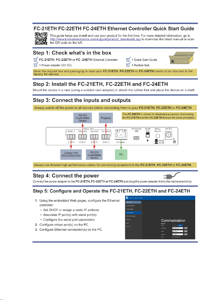
To connect the FC-24ETH as illustrated in the example in Figure 9:
1. Connect the device to a LAN or PC via the RJ-45 Ethernet connector.
2. Connect up to 4 serially controlled devices, (for example, an RS-232/RS-485
controlled device, a projector and two other devices) to the 3-pin, RS-232
terminal blocks.
3. Connect the device to the power adapter and connect the power adapter to
the mains electricity (not shown in Figure 9).
Page 21

Connecting the FC-21ETH, FC-22ETH and FC-24ETH
17
This type of connection is recommended for identifying the FC-24ETH
with the factory configured default IP address.
i
6.1 Connecting via Ethernet
You can connect to the FC-24ETH via Ethernet using either of the following
methods:
Directly to the PC using a crossover cable (see Section 6.1.1)
Via a network hub, switch, or router, using a straight-through cable (see
Section 6.1.2)
Note: If you want to connect via a router and your IT system is based on IPv6,
speak to your IT department for specific installation instructions.
6.1.1 Connecting the Ethernet Port Directly to a PC
You can connect the Ethernet port of the FC-24ETH directly to the Ethernet port on
your PC using a crossover cable with RJ-45 connectors.
After connecting the FC-24ETH to the Ethernet port, configure your PC as follows:
1. Click Start > Control Panel > Network and Sharing Center.
2. Click Change Adapter Settings.
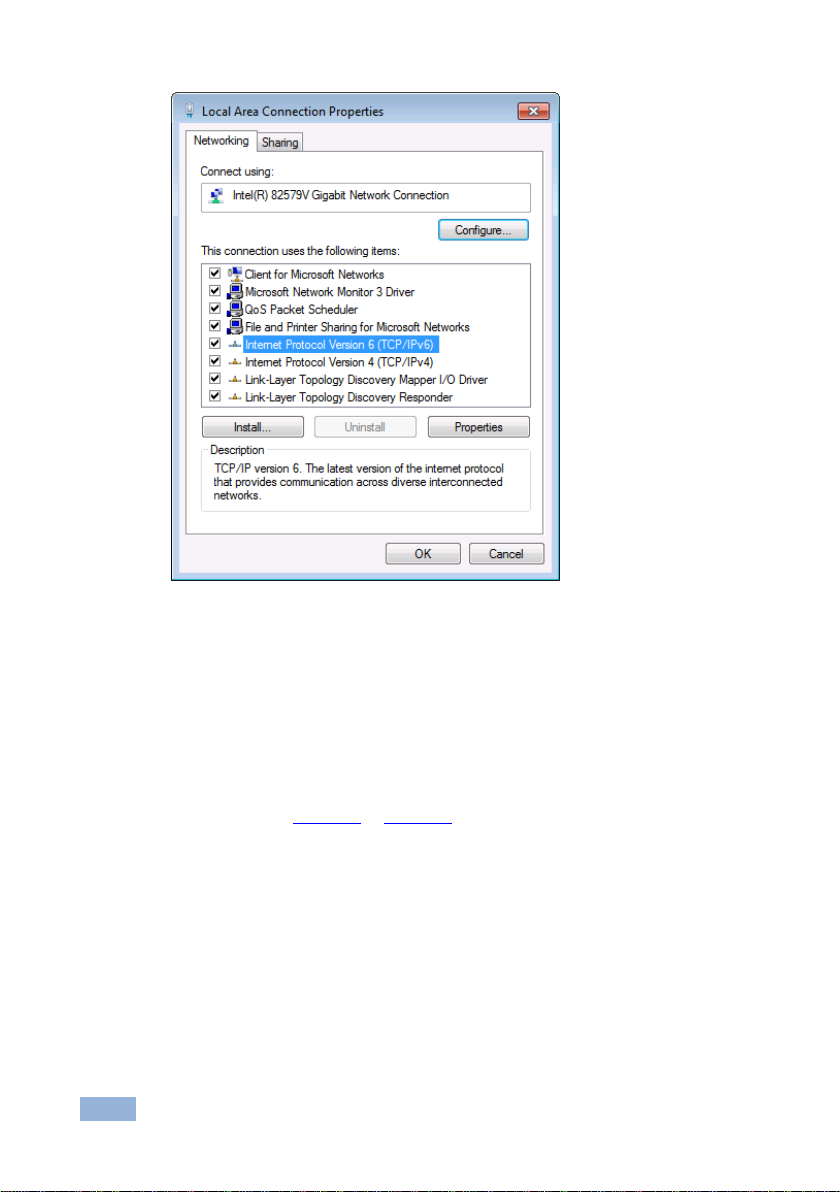
3. Highlight the network adapter you want to use to connect to the device and
click Change settings of this connection.
The Local Area Connection Properties window for the selected network
adapter appears as shown in Figure 10.
Page 22
18
Connecting the FC-21ETH, FC-22ETH and FC-24ETH
Figure 10: Local Area Connection Properties Window
4. Highlight either Internet Protocol Version 6 (TCP/IPv6) or Internet
Protocol Version 4 (TCP/IPv4) depending on the requirements of your IT
system.
5. Click Properties.
The Internet Protocol Properties window relevant to your IT system appears
as shown in Figure 11 or Figure 12.
Page 23

Connecting the FC-21ETH, FC-22ETH and FC-24ETH
19
Figure 11: Internet Protocol Version 4 Properties Window
Figure 12: Internet Protocol Version 6 Properties Window
Page 24

20
Connecting the FC-21ETH, FC-22ETH and FC-24ETH
6. Select Use the following IP Address for static IP addressing and fill in the
details as shown in Figure 13.
For TCP/IPv4 you can use any IP address in the range 192.168.1.1 to
192.168.1.255 (excluding 192.168.1.39) that is provided by your IT
department.
Figure 13: Internet Protocol Properties Window
7. Click OK.
8. Click Close.
6.1.2 Connecting the Ethernet Port via a Network Hub or Switch
You can connect the Ethernet port of the FC-24ETH to the Ethernet port on a
network hub or using a straight-through cable with RJ-45 connectors.
Page 25

Connecting the FC-21ETH, FC-22ETH and FC-24ETH
21
6.2 Connecting to the Ethernet Controller via RS-232
To connect to the FC-21ETH, FC-22ETH and FC-24ETH via RS-232:
Connect the RS-232, 3-pin, terminal block connectors on the rear panel of
the FC-21ETH, FC-22ETH and FC-24ETH unit via 3-wire cable (pin TX to
pin 2, RX to pin 3, and G to pin 5) to the RS-232 9-pin D-sub port on the
devices to be controlled
6.3 Connecting to a Controlled Device via the RS-485 Port
You can control a device up to 1200m (3900ft) away by using the RS-232/RS-485
port on the FC-21ETH, FC-22ETH and FC-24ETH and setting it to RS-485
operation. To connect via RS-485, you must switch the Serial 1 port on the rear
panel of the FC-21ETH, FC-22ETH and FC-24ETH to RS-485 operation and set
the RS-485 bus termination.
Note: On the dual-use Serial port, the connections are G, B, A in place of G, Rx,
Tx.
To connect a device with an RS-485 port to the FC-21ETH, FC-22ETH and
FC-24ETH:
1. Depress the Serial Select switch on the rear panel of the FC-21ETH,
FC-22ETH and FC-24ETH.
2. Connect the devices as follows:
Connect the B (–) pin on the RS-485 port of the PC to the Tx (A) pin on
the RS-485 port on the rear panel of the FC-21ETH, FC-22ETH and
FC-24ETH
Connect the A (+) pin on the RS-485 port of the PC to the Rx (B) pin on
the RS-485 port on the rear panel of the FC-21ETH, FC-22ETH and
FC-24ETH
Connect the G pin on the RS-485 port of the PC to the G pin on the
RS-485 port on the rear panel of the FC-21ETH, FC-22ETH and
FC-24ETH
Page 26

22
Connecting the FC-21ETH, FC-22ETH and FC-24ETH
3. Terminate the RS-485 bus at the FC-21ETH/FC-22ETH/FC-24ETH by
sliding the RS-485 Term switch on the rear panel of the FC-21ETH,
FC-22ETH and FC-24ETH down.
Page 27

Operating the FC-21ETH, FC-22ETH and FC-24ETH Remotely via the Web Pages
23
7 Operating the FC-21ETH, FC-22ETH and
FC-24ETH Remotely via the Web Pages
The embedded Web pages can be used to remotely operate the FC-21ETH,
FC-22ETH and FC-24ETH using a Web browser and an Ethernet connection.
Before attempting to connect:
Perform the procedures in Section 6.1.
Ensure that your browser is supported (see Section 9)
Note: The FC-24ETH is used throughout this chapter as an example. The same
principles apply to the FC-21ETH and the FC-22ETH.
7.1 Browsing the FC-24ETH Web Pages
To browse the FC-24ETH Web pages:
1. Open your Internet browser.
2. Type the device’s IP number (see Section 10) in the Address bar of your
browser.
The Loading page appears followed shortly by the General Info page shown in
Figure 14.
The General Info page displays the following:
Model Name
Firmware version
Device serial number
Web page version
Page 28

24
Operating the FC-21ETH, FC-22ETH and
FC-24ETH Remotely via the Web Pages
At the bottom left hand side of all pages there are Load/Save Configuration
buttons. These allow you to save the current configuration and load any presaved
configurations.
Figure 14: General Info Page
Page 29
Operating the FC-21ETH, FC-22ETH and
FC-24ETH Remotely via the Web Pages
25
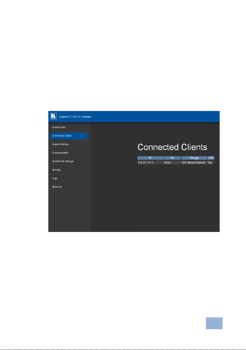
7.2 Connected Clients Page
The Connected Clients page is informational and allows you to view the following
details of any client devices connected via Ethernet to the FC-24ETH:
IP address
The port it is connected to
Method of connection
Whether or not Send Replies is enabled for the port
Figure 15: Connected Clients Page
Page 30
26
Operating the FC-21ETH, FC-22ETH and
FC-24ETH Remotely via the Web Pages
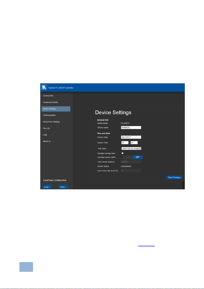
7.3 Device Settings Page
The Device Settings page allows you to view the model name and time server
status, and modify the following fields:
Device name
Time and date automatically using a Time Server (if the device is connected
to the Internet), including the Time Zone and daylight savings time
Time and date manually
Figure 16: Device Settings Page
The FC-24ETH has a built-in clock that can synchronize with a Time Server if
required.
To enable Time Server synchronization:
1. Browse to the Device Settings page by clicking Device Settings.
The Device Settings page is displayed as shown in Figure 16.
2. Click the Use Time Server ON button.
Page 31

Operating the FC-21ETH, FC-22ETH and
FC-24ETH Remotely via the Web Pages
27
3. Enter the IP address of the Time Server.
4. Enter the time of day at which the FC-24ETH should synchronize with the
Time Server.
7.4 Communication Page
The communication page allows you to:
Turn DHCP for the device on and off
Edit the IP settings for static IP
5. Click Save Changes.
Figure 17: Communication Page
After modifying any of the IP settings, click Set to save the changes.
Page 32

28
Operating the FC-21ETH, FC-22ETH and
FC-24ETH Remotely via the Web Pages
7.5 Serial Port Settings Page
The Serial Port Settings page allows you to:
Set the following Ethernet parameters for each Ethernet port:
Select TCP or UDP
IP port label
TCP keep alive time
Set the following serial parameters for each serial port:
Parity
Data bits
Baud rates
Stop bits
Select whether or not to send replies on the port to the new client
Figure 18: Serial Port Settings Page
Page 33

Operating the FC-21ETH, FC-22ETH and
FC-24ETH Remotely via the Web Pages
29
7.6 Security Page
The Security page allows you to turn the security for the device on or off.
Figure 19: Security Page
When security is on, access to the Web pages is only granted on submission of a
valid user and password. The default credentials are “admin” and no password.
To activate Web page security:
1. On the Security page, click ON.
The confirmation popup is displayed as shown in Figure 20.
Figure 20: Security Confirmation Popup
2. Click OK.
The Authentication Required popup is displayed as shown in Figure 21.
Page 34

30
Operating the FC-21ETH, FC-22ETH and
FC-24ETH Remotely via the Web Pages
Figure 21: Authentication Required Popup
3. Enter the default User Name and Password.
4. Click OK.
5. Wait until the Web pages have reloaded and click to browse to the Security
page.
The page show in Figure 22 is displayed.
Figure 22: Security Activated Page
6. If required, turn security off by clicking OFF or change the password and
click Change.
Page 35

Operating the FC-21ETH, FC-22ETH and
FC-24ETH Remotely via the Web Pages
31
7.7 Logs Page
The Logs page allows you to:
View current logs
Configure the logs
Filter the logs
Figure 23: Logs Page
The display is not updated automatically. Click Refresh to update the display.
Use the Log Config check-boxes to select which events are recorded. Use the Log
Filter check-boxes to select which events to display from the log.
Page 36

32
Operating the FC-21ETH, FC-22ETH and
FC-24ETH Remotely via the Web Pages
7.8 About Us Page
The About Us page displays the Web page version and the Kramer company
details.
Figure 24: About Us Page
Page 37

Configuring and Maintaining the FC-21ETH, FC-22ETH and FC-24ETH
33
8 Configuring and Maintaining the FC-21ETH,
FC-22ETH and FC-24ETH
This section describes:
Selecting the RS-232 or RS-485 Port (see Section 8.1)
Terminating the RS-485 bus (see Section 8.2)
Activating DHCP (see Section 8.3)
Resetting to the factory default settings (see Section 8.4)
Upgrading the firmware (see Section 8.5)
8.1 Selecting the RS-232 or RS-485 Serial Port
The 3-pin Serial terminal block can be used as either an RS-232 or as an RS-485
port.
To set the Serial port as an RS-232 port:
Release the RS-232/RS-485 button on the rear panel.
The Serial RS-232 LED lights
To set the Serial port as an RS-485 port:
Depress the RS-232/RS-485 button on the rear panel.
The Serial RS-485 LED lights
8.2 Terminating the RS-485 Bus
The devices at both ends of the RS-485 chain must be terminated; all other
devices in the chain must be left unterminated.
To terminate the RS-485 bus:
Slide the RS-485 Term switch down
Page 38

34
Configuring and Maintaining the FC-21ETH,
FC-22ETH and FC-24ETH
8.3 Activating DHCP
The IP address of the FC-21ETH, FC-22ETH and FC-24ETH can be set either
statically or dynamically where it is issued by a DHCP server.
To activate and deactivate DHCP:
1. Press the DHCP button on the front panel.
DHCP is activated, the DHCP LED lights green.
2. Press the DHCP button again.
DHCP is deactivated and the DHCP LED no longer lights.
8.4 Resetting to the Factory Default Settings
To reset the device to its factory default settings:
1. Turn off the power to the device.
2. Press and hold the Reset button on the front panel.
3. Turn on the power to the device while holding down the Reset button for a
few seconds.
4. Release the button.
The device is reset to the factory default settings.
8.5 Upgrading the Firmware
For instructions on upgrading the firmware see the “Kramer K-Upload User
Manual”.
Page 39
Technical Specifications
35
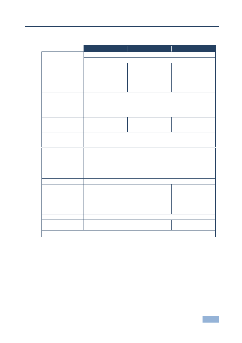
FC-21ETH
FC-22ETH
FC-24ETH
PORTS:
1 Ethernet on an RJ-45 connector
1 USB on a mini USB connector for programming
1 RS-232/RS-485
serial port on a 3-pin
terminal block
1 RS-232/RS-485
serial port on a 3-pin
terminal block
1 RS-232 serial port
on 3-pin terminal
blocks
1 RS-232/RS-485
serial port on a 3-pin
terminal block
3 RS-232 serial ports
on 3-pin terminal
blocks
MAXIMUM SERIAL
PORT BAUD
RATE:
115200bps
RS-232
COMMUNICATION:
Transparent up to 115200bps
OVERALL DEVICE
BAUDRATE
SUPPORT:
150kbps
140kbps
180kbps
SUPPORTED WEB
BROWSERS:
Microsoft IE V9.0 and higher
Google Chrome
Firefox V3.0 and higher
POWER
CONSUMPTION:
200mA
OPERATING
TEMPERATURE:
0° to +40°C (32° to 104°F)
STORAGE
TEMPERATURE:
–40° to +70°C (–40° to 158°F)
HUMIDITY:
10% to 90%, RHL non-condensing
DIMENSIONS:
12.1cm x 6.97cm x 2.48cm
(4.76” x 2.74” x 0.98”) W, D, H
18.8cm x 11.3cm x
2.5cm
(7.4” x 4.5” x 1”) W,
D, H
WEIGHT:
0.48kg (1.1lbs) approx.
0.72kg (1.59lbs)
approx.
ACCESSORIES:
Power adapter
OPTIONS:
19“ Rack adapter RK-3T
19“ Rack adapter
RK-T2B
Specifications are subject to change without notice at http://www.kramerelectronics.com
9 Technical Specifications
9.1 Data Handling Performance
The FC-21ETH, FC-22ETH and FC-24ETH are designed to support mainly AVrelevant RS-232 communication.
These devices have overall data bandwidth limits which should be high enough in
most AV installations to support the required communication bandwidth.
Page 40

36
Technical Specifications
In extremely demanding cases, we recommend that you take into account the
bandwidth limitations.
The total sustained data bandwidth that each device can handle for all ports
simultaneously is as follows:
FC-21ETH—150kbps
FC-22ETH—140kbps
FC-24ETH—180kbps
9.2 Example Bandwidth Calculation
The FC-22ETH has two serial ports. Each serial port can support up to:
140kbps / 2 = 70kbps
If each of your protocol commands is 100 bytes, (that is, 800bits), you can safely
send and/or receive a minimum of 85 of these commands per second on each
serial port ((140kbps * 1024) / 800bits / 2 = 89.2). The same calculation applies to
all devices. A similar calculation applies when fewer ports are used at the same
time; in this case higher bandwidth per port can be achieved.
In critical applications requiring a lossless data transfer, we recommend that
communication on all the other ports is stopped when making a long file transfer
(for example, when performing a firmware upgrade via one of the serial ports).
Page 41

Default Communication Parameters
37
RS-232
Protocol 3000
Baud Rate:
115200
Data Bits:
8
Stop Bits:
1
Parity:
None
Ethernet
IP Address:
192.168.1.39
TCP Port Number:
5000
Network Mask:
255.255.0.0
Default Gateway:
192.168.0.1
10 Default Communication Parameters
Page 42

38
Kramer Protocol 3000
Start
Address
(optional)
Body
Delimiter
#
Destination_id@
Message
CR
Start
Body
Delimiter
#
Command SP Parameter_1,Parameter_2,…
CR
Start
Address
Body
Delimiter
#
Destination_id@
Command_1
Parameter1_1,Parameter1_2,…|
Command_2
Parameter2_1,Parameter2_2,…|
Command_3
Parameter3_1,Parameter3_2,…|…
CR
Start
Address
(optional)
Body
delimiter
~
Sender_id@
Message
CR LF
Start
Address
(optional)
Body
Delimiter
~
Sender_id@
Command SP [Param1 ,Param2 …] result
CR LF
11 Kramer Protocol 3000
The FC-21ETH can be operated using serial commands from a PC, remote
controller or touch screen using the Kramer Protocol 3000.
This section describes:
Kramer Protocol 3000 syntax (see Section 11.1)
Kramer Protocol 3000 commands (see Section 11.2)
11.1 Kramer Protocol 3000 Syntax
11.1.1 Host Message Format
11.1.1.1 Simple Command
Command string with only one command without addressing:
11.1.1.2 Command String
Formal syntax with commands concatenation and addressing:
11.1.2 Device Message Format
11.1.2.1 Device Long Response
Echoing command:
Page 43

Kramer Protocol 3000
39
CR = Carriage return (ASCII 13 = 0x0D)
LF = Line feed (ASCII 10 = 0x0A)
SP = Space (ASCII 32 = 0x20)
11.1.3 Command Terms
Command
A sequence of ASCII letters ('A'-'Z', 'a'-'z' and '-').
Command and parameters must be separated by at least one space.
Parameters
A sequence of alphanumeric ASCII characters ('0'-'9','A'-'Z','a'-'z' and some special
characters for specific commands). Parameters are separated by commas.
Message string
Every command entered as part of a message string begins with a message
starting character and ends with a message closing character.
Note: A string can contain more than one command. Commands are separated by
a pipe ( '|' ) character.
Message starting character
'#' – For host command/query
'~' – For device response
Device address (Optional, for K-NET)
K-NET Device ID followed by '@'
Query sign
'?' follows some commands to define a query request.
Message closing character
CR – For host messages; carriage return (ASCII 13)
CRLF – For device messages; carriage return (ASCII 13) + line-feed (ASCII 10)
Command chain separator character
When a message string contains more than one command, a pipe ( '|' ) character
separates each command.
Page 44

40
Kramer Protocol 3000
Command
Description
#
Protocol handshaking
BUILD-DATE?
Read device build date
FACTORY
Restart the machine with the default
HELP
List of commands
LOGIN
Elevates terminal security level
LOGIN?
Displays current terminal security level
LOGOUT
Demotes the terminal security level to minimum
MODEL?
Read device model
Spaces between parameters or command terms are ignored.
11.1.4 Entering Commands
You can directly enter all commands using a terminal with ASCII communications
software, such as HyperTerminal, Hercules, etc. Connect the terminal to the serial
or Ethernet port on the Kramer device. To enter CR press the Enter key.
( LF is also sent but is ignored by command parser).
For commands sent from some non-Kramer controllers like Crestron, some
characters require special coding (such as, /X##). Refer to the controller manual.
11.1.5 Command Forms
Some commands have short name syntax in addition to long name syntax to allow
faster typing. The response is always in long syntax.
11.1.6 Chaining Commands
Multiple commands can be chained in the same string. Each command is
delimited by a pipe character (“|”). When chaining commands, enter the message
starting character and the message closing character only once, at the
beginning of the string and at the end.
Commands in the string do not execute until the closing character is entered.
A separate response is sent for every command in the chain.
11.1.7 Maximum String Length
64 characters
11.2 Kramer Protocol 3000 Commands
Page 45

Kramer Protocol 3000
41
Command
Description
NAME?
Get device name
NET-DHCP
Sets DHCP on or off
NET-DHCP?
Checks if DHCP on or off
NET-GATE
Sets the network gateway
NET-GATE?
Gets the network gateway
NET-IP
Sets the IP
NET-IP?
Get the IP
NET-MAC?
Gets the MAC address
NET-MASK
Sets the subnet mask
NET-MASK?
Gets the subnet mask
PASS
Sets the password
PASS?
Gets the password
PROT-VER?
Read device protocol version
RESET
Reset device
SECUR
Sets security on or off
SECUR?
Indicates whether security is on or off
SN?
Read device serial number
TIME
Sets the time
TIME?
Gets the time
TIME-LOC
Sets the time zone and DST
TIME-LOC?
Gets the timezone and DST
TIME-SRV
Sets the NTP server parameters
TIME-SRV?
Gets the NTP server parameters
UART
Sets a port serial parameters
UART?
Gets a port serial parameters
VERSION?
Read device firmware version
Page 46

Page 47

For the latest information on our products and a list of Kramer distributors,
visit our Web site where updates to this user manual may be found.
We welcome your questions, comments, and feedback.
Web site: www.kramerelectronics.com
E-mail: info@kramerel.com
P/N:
2900- 300221
Rev:
1
!
SAFETY WARNIN G
Disconnect the unit from the power
supply before opening and servicing
 Loading...