

Page 1

KRAMER ELECTRONIC S LTD.
USER MANUAL
MODEL:
FC-1 0E TH
Ethernet Controller
P/N: 2900-000086 Rev 3
Page 2
Page 3

FC-10ETH – Contents
i
Contents
1 Introduction 1
2 Getting Started 2
2.1 Achieving the Best Performance 2
2.2 Safety Instructions 2
2.3 Recycling Kramer Products 3
3 Overview 4
3.1 Defining the FC-10ETH Ethernet Controller 5
4 Configuring the FC-10ETH Ethernet Controller 7
4.1 Operating via Ethernet 7
4.2 Installing and Configuring the FC-10ETH 11
4.3 Defining the Kramer FC-10ETH Manager 12
4.4 Routing Data 13
5 Controlling Machines via the Ethernet using the FC-10ETH 15
5.1 Controlling a Machine via a Computer 15
5.2 Controlling a Kramer Machine via a Serial Controller 17
6 Flash Memory Upgrade 20
6.1 Upgrading Version 1 Devices 20
6.2 Upgrading Version 2 Devices 21
7 Technical Specifications 22
Figures
Figure 1: FC-10ETH Ethernet Controller 5
Figure 2: Underside of the FC-10ETH Ethernet Controller 5
Figure 3: Local Area Connection Properties Window 8
Figure 4: Internet Protocol Version 4 Properties Window 9
Figure 5: Internet Protocol Version 6 Properties Window 9
Figure 6: Internet Protocol Properties Window 10
Figure 7: Connecting the FC-10ETH for Configuration 11
Figure 8: FC-10ETH Manager Window 12
Figure 9: Connecting the FC-10ETH in the Passive Routing Mode 16
Figure 10: The Port Window – Selecting a Remote Connection 17
Figure 11: Connecting the FC-10ETH in the Active Routing Mode 19
Figure 12: The KFR-Programmer Window 21
Page 4

FC-10ETH – Introduction
1
1 Introduction
Welcome to Kramer Electronics! Since 1981, Kramer Electronics has been
providing a world of unique, creative, and affordable solutions to the vast range of
problems that confront video, audio, presentation, and broadcasting professionals
on a daily basis. In recent years, we have redesigned and upgraded most of our
line, making the best even better!
Our 1,000-plus different models now appear in 11 groups that are clearly defined
by function: GROUP 1: Distribution Amplifiers; GROUP 2: Switchers and Routers;
GROUP 3: Control Systems; GROUP 4: Format/Standards Converters; GROUP 5:
Range Extenders and Repeaters; GROUP 6: Specialty AV Products; GROUP 7:
Scan Converters and Scalers; GROUP 8: Cables and Connectors; GROUP 9:
Room Connectivity; GROUP 10: Accessories and Rack Adapters and GROUP 11:
Sierra Video Products.
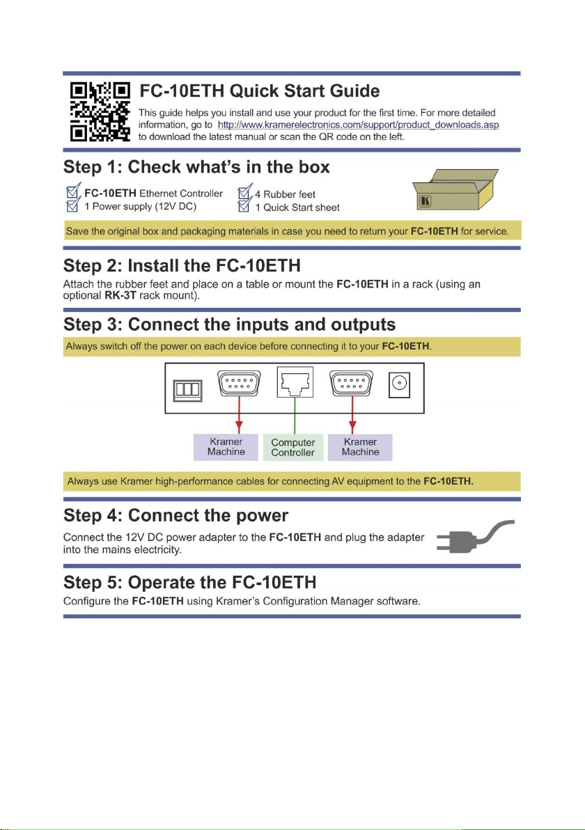
Congratulations on purchasing your Kramer FC-10ETH Ethernet Controller, which
is ideal for use with Ethernet / RS-232 interfaces and/or Ethernet / RS-485
interfaces.
Page 5

2
FC-10ETH - Getting Started
Go to http://www.kramerelectronics.com/support/product_downloads.asp
to check for up-to-date user manuals, application programs, and to check if
firmware upgrades are available (where appropriate).
This equipment is to be used only inside a building. It may only be
connected to other equipment that is installed inside a building.
Caution:
There are no operator serviceable parts inside the unit
Warning:
Use only the Kramer Electronics input power wall
adapter that is provided with the unit
Warning:
Disconnect the power and unplug the unit from the wall
before installing
i
!
!
2 Getting Started
We recommend that you:
Unpack the equipment carefully and save the original box and packaging
materials for possible future shipment
Review the contents of this user manual
2.1 Achieving the Best Performance
To achieve the best performance:
Use only good quality connection cables (we recommend Kramer high-
performance, high-resolution cables) to avoid interference, deterioration in
signal quality due to poor matching, and elevated noise levels (often
associated with low quality cables)
Do not secure the cables in tight bundles or roll the slack into tight coils
Avoid interference from neighboring electrical appliances that may adversely
influence signal quality
Position your Kramer FC-10ETH away from moisture, excessive sunlight and
dust
2.2 Safety Instructions
Page 6

FC-10ETH – Getting Started
3
2.3 Recycling Kramer Products
The Waste Electrical and Electronic Equipment (WEEE) Directive 2002/96/EC
aims to reduce the amount of WEEE sent for disposal to landfill or incineration by
requiring it to be collected and recycled. To comply with the WEEE Directive,
Kramer Electronics has made arrangements with the European Advanced
Recycling Network (EARN) and will cover any costs of treatment, recycling and
recovery of waste Kramer Electronics branded equipment on arrival at the EARN
facility. For details of Kramer’s recycling arrangements in your particular country
go to our recycling pages at http://www.kramerelectronics.com/support/recycling/.
Page 7

4
FC-10ETH - Overview
3 Overview
The high-performance FC-10ETH Ethernet Controller is an easy-to-use,
bidirectional hardware and software interface system for controlling Kramer (and
also non-Kramer) RS-232 and/or RS-485 controllable machines via Ethernet LAN,
as well as via the Internet. In particular, the FC-10ETH features:
Network connectivity that lets you connect a Kramer (or other) device via its
RS-232 or RS-485 port to the Ethernet LAN network
The FC-10ETH data buffer is limited to 128 bytes
Control of two RS-232 devices (or one RS-232 device and one RS-485
device) via Ethernet, from a PC (set to the Passive routing mode) or other
protocol compatible remote controller
Device control from up to five Ethernet points (PCs or remote controllers)
Windows®-based Configuration Management software for configuring the
FC-10ETH unit (including routing mode settings, network settings, serial
settings, and destination device settings)
Internet system remote control (requiring only a dedicated IP address and a
modem in the remote location) whether it is a standalone PC or a LAN
system
A 128-byte data buffer making it compatible with most non-Kramer protocols
The FC-10ETH includes the Virtual Serial Port Manager (Kramer VSPM) for
compatibility with applications based on COM-port communication. The virtual
serial port:
Makes the FC-10ETH compatible with all Windows®-based applications that
work through an actual COM port. This includes all versions of K-Router and
other Kramer control applications. It lets you operate all RS-232 and RS-485
controllable devices via Ethernet LAN using their existing PC software
Operates like an actual hardware port, that is, a logical COM that behaves
like a standard hardware COM but in reality transparently reroutes the data
using the TCP/IP network to the FC-10ETH interface via a Virtual null
modem connection, which you can emulate over the Ethernet or Internet
Can be created in any quantity on your PC and does not occupy an actual
serial port
Page 8
FC-10ETH – Overview
5
3.1 Defining the FC-10ETH Ethernet Controller
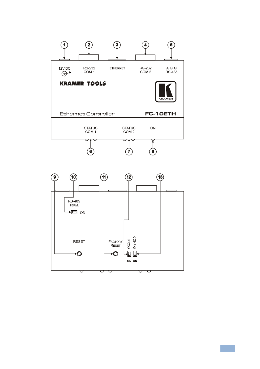
Figure 1: FC-10ETH Ethernet Controller
Figure 2: Underside of the FC-10ETH Ethernet Controller
Page 9

6
FC-10ETH - Overview
#
Feature
Function
1
12V DC
+12V DC connector for powering the unit
2
RS-232 COM 1 Port
Connects to the RS-232 9-pin D-sub port on the Kramer (or
other) device 1 or PC
3
ETHERNET Port
Connects to your LAN
4
RS-232 COM 2 Port
Connects to the RS-232 9-pin D-sub port on a Kramer (or
other) device 2 or PC
A Kramer device can be connected to either the RS-232 COM 2
port, or to the RS-485 terminal block port (but not to both)
5
RS-485 Terminal
Block Port
Connects to the RS-485 port on a Kramer (or other) device
A Kramer device can be connected to either the RS-232 COM 2
port, or to the RS-485 terminal block port (but not to both)
PIN A connects to the “A” (+) PIN; PIN B connects to the “B”
(–) PIN (and PIN G connects to the “G (Ground)” PIN, if
necessary)
The connection to G is usually not necessary for RS-485
6
STATUS COM 1 LEDs
Lit when a signal is transmitted or received from port 1
(mostly used for troubleshooting)
7
STATUS COM 2 LEDs
Lit when a signal is transmitted or received from port 2
(mostly used for troubleshooting)
8
ON LED
Lit when receiving power
9
RESET Button
Press to reset the machine
Turns the machine off and on again while retaining its definitions
(identical to disconnecting the power adapter and then
connecting it again)
10
RS-485 TERM. Button
Press for BUS termination:
Set to OFF if the RS-485 terminal block port is not connected
Set to ON if the RS-485 terminal block port is connected
11
FACTORY RESET
Button
Press to reset to factory default definitions
First disconnect the power adapter and then connect it again
while pressing the FACTORY RESET button. The unit will power
up and load its memory with the factory default definitions
12
PROG Switch
Switch ON to upgrade firmware
13
CONFIG Switch
Not used, set to OFF
Page 10

FC-10ETH – Configuring the FC-10ETH Ethernet Controller
7
This type of connection is recommended for identifying the FC-10ETH
with the factory configured default IP address.
i
4 Configuring the FC-10ETH Ethernet
Controller
This section describes:
How to connect the FC-10ETH for configuration, via its ETHERNET port
(see Section 4.1)
How to install and run the Configuration Manager software (see Section 4.2)
The Configuration Manager Window features (see Section 4.3)
4.1 Operating via Ethernet
You can connect to the product via Ethernet using either of the following
methods:
Directly to the PC using a crossover cable (see Section 4.1.1)
Via a network hub, switch, or router, using a straight-through cable (see
Section 4.1.2)
Note: If you want to connect via a router and your IT system is based on IPv6,
speak to your IT department for specific installation instructions.
4.1.1 Connecting the Ethernet Port Directly to a PC
You can connect the Ethernet port of the FC-10ETH directly to the Ethernet port on
your PC using a crossover cable with RJ-45 connectors.
After connecting the FC-10ETH to the Ethernet port, configure your PC as follows:
1. Click Start > Control Panel > Network and Sharing Center.
2. Click Change Adapter Settings.
3. Highlight the network adapter you want to use to connect to the device and
click Change settings of this connection.
Page 11
8
FC-10ETH - Configuring the FC-10ETH Ethernet Controller
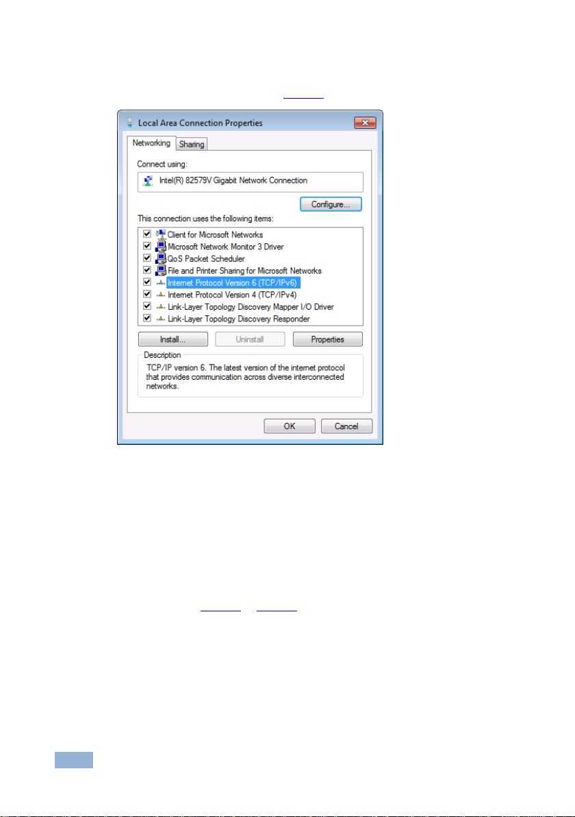
The Local Area Connection Properties window for the selected network
adapter appears as shown in Figure 3.
Figure 3: Local Area Connection Properties Window
4. Highlight either Internet Protocol Version 6 (TCP/IPv6) or Internet
Protocol Version 4 (TCP/IPv4) depending on the requirements of your IT
system.
5. Click Properties.
The Internet Protocol Properties window relevant to your IT system appears
as shown in Figure 4 or Figure 5.
Page 12
FC-10ETH – Configuring the FC-10ETH Ethernet Controller
9
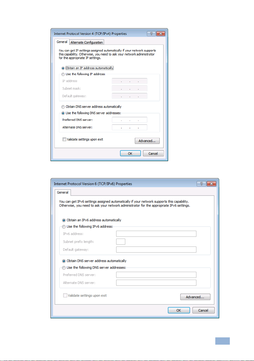
Figure 4: Internet Protocol Version 4 Properties Window
Figure 5: Internet Protocol Version 6 Properties Window
Page 13

10
FC-10ETH - Configuring the FC-10ETH Ethernet Controller
6. Select Use the following IP Address for static IP addressing and fill in the
details as shown in Figure 6.
For TCP/IPv4 you can use any IP address in the range 192.168.1.1 to
192.168.1.255 (excluding 192.168.1.39) that is provided by your IT
department.
Figure 6: Internet Protocol Properties Window
7. Click OK.
8. Click Close.
4.1.2 Connecting the Ethernet Port via a Network Hub or Switch
You can connect the Ethernet port of the FC-10ETH to the Ethernet port on a
network hub or using a straight-through cable with RJ-45 connectors.
4.1.3 Control Configuration via the Ethernet Port
To control several units via Ethernet, connect the Master unit (Device 1) via the
Ethernet port to the Ethernet port of your PC. Use your PC provide initial
configuration of the settings (see Section 4.1).
Page 14

FC-10ETH – Configuring the FC-10ETH Ethernet Controller
11
Note that clicking the Config button will alter the IP settings of the
FC-10ETH.
i
4.2 Installing and Configuring the FC-10ETH
To configure the FC-10ETH via the ETHERNET, do the following:
1. Connect the FC-10ETH as described in Section 4.1 (see Figure 7)
2. Click the appropriate shortcut in the Start menu’s Programs folder.
The FC-10ETH Configuration Manager window (see Figure 8) opens.
3. Click the Search button to automatically search for devices (or the Search
Board command on the Action menu).
The MAC Address for the found “FC-10ETH” appears in the Device List.
4. Change the settings according to your network requirements and then click
the Config button (or the Config command on the Action menu) to apply the
settings.
Figure 7: Connecting the FC-10ETH for Configuration
Page 15

12
FC-10ETH - Configuring the FC-10ETH Ethernet Controller
#
Feature
Function
1
Menu Bar
DEVICE
Search for all connected devices
Upload configuration to device (same as button 4)
SETTINGS
Sets the broadcast address and the broadcast network
interface
ABOUT
Displays software development information, including the
software version
2
Search Button
Seeks the FC-10ETH devices that connect to the PC via the
ETHERNET port, and displays them and their corresponding
settings
3
Device List
Displays the MAC Addresses for the FC-10ETH devices,
connected via the selected port (LAN or COM) and the version
(V1 and V2) of the device
4
UPLOAD TO DEVICE
Press to upload the displayed configuration to the device
5
FC-10ETH Setting
FIRMWARE
VERSION
Displays the firmware version
6
MAC ADDRESS
Displays the MAC Addresses for the FC-10ETH devices,
connected via the selected port (LAN or COM)
7
IP ADDRESS
A 32-binary digit number obtained from your Network
Administrator that identifies the FC-10ETH device that is
currently being configured in the Ethernet or Internet
8
SUBNET
A 32-binary digit number obtained from your Network
Administrator, which combined with the IP Address, identifies
which network your FC-10ETH device is on
9
GATEWAY
A network position serving as an entry to another network or
to the Internet
(only relevant in the Active Routing mode)
4.3 Defining the Kramer FC-10ETH Manager
Figure 8: FC-10ETH Manager Window
Page 16

FC-10ETH – Configuring the FC-10ETH Ethernet Controller
13
#
Feature
Function
10
Data Channel Setting
LOCAL IP PORT
An address (for the local ports COM 1 and COM 2) on the
FC-10ETH device that is currently being configured, which
provides a direct route from another Ethernet point application
11
UART SPEED
Choose the appropriate baud speed (1200, 2400, 4800, 9600,
19200, 38400, 57600 or 115200)
12
UART PARITY
Choose the required parity (None, Odd, Even, Mark or Space)
13
ACTIVE Checkbox
When cleared, activates the Passive mode (see Section 4.4.1)
When selected, activates the Active mode (see Section 4.4.2)
Note: Only appears for V1 devices, not present for V2 devices
14
DESTINATION IP
A 32-binary digit number that identifies the destination
FC-10ETH device in the Ethernet or Internet
15
PORT
A pre-assigned address of the destination FC-10ETH device
that provides a direct route to its Transport layer
The Destination Settings area is active only when the Active
Mode check box is selected
4.4 Routing Data
There are two versions of the FC-10ETH, version 1 (V1) and version 2 (V2). The
version is shown on the Device List entry (see item 3 on Figure 8).
V1 devices use passive (see Section 4.4.1) and active (Section 4.4.2)
routing modes. The Active checkbox (see item 13 on Figure 8) is displayed
only for V1 devices
V2 devices only use the passive routing mode (see Section 4.4.1). No Active
checkbox is displayed for V2 devices
4.4.1 The Passive Routing Mode for V1 and V2 Devices
In the Passive routing mode, the FC-10ETH never opens the Ethernet
communication first, and only replies to the connection requests coming from the
active remote stations. Serial data that is received at the serial port of the
FC-10ETH, before the remote station contacts the FC-10ETH, is discarded.
In the Passive mode, the FC-10ETH will work with any station on the network that
contacts it (but not more than five stations simultaneously, three via COM 1 and
two via COM 2), as the example in Figure 9 illustrates.
Page 17

14
FC-10ETH - Configuring the FC-10ETH Ethernet Controller
To configure the FC-10ETH to the Passive mode, connect it and do the following:
Only for V.1 devices because this is the default mode. V.2 has no configuration.
1. Press the Search button to find the device connected to the PC.
2. Set the IP address number according to your network requirements.
3. For V1 devices, clear the Active Mode check box (if selected) in the
configuration manager. (This does not appear for V2 devices).
4. Press the Config button to accept changes.
4.4.2 The Active Routing Mode for V1 Devices Only
In the Active routing mode (V1 devices only), the FC-10ETH does not wait for the
remote station to send the connection request first, it sends the connection request
and routes the data in the destination device direction as soon as there is data to
be sent. The data is always sent to a specific destination (as defined by the
Destination IP address and the Destination Port Number Settings of the
FC-10ETH).
To configure the FC-10ETH to the Active mode, connect it and do the following:
1. Press the Search button to find the device connected to the PC.
2. Set the IP address number according to your network requirements.
3. Select the Active Mode check box in the configuration manager.
4. Set the Destin. IP and Port in the Destination Settings Area, for CHANNEL 1
and CHANNEL 2.
5. Press the Config button to accept changes.
Page 18

FC-10ETH – Controlling Machines via the Ethernet using the FC-10ETH
15
5 Controlling Machines via the Ethernet using
the FC-10ETH
You can use your FC-10ETH to control a Kramer or non-Kramer RS-232/RS-485
machine:
From computers that connect to a LAN, as well as via an Internet connection
(see Section 5.1)
Via a controller, as well as via an Internet connection (see Section 5.2).
5.1 Controlling a Machine via a Computer
To control a Kramer machine via five computers, as illustrated in the example in
Figure 9, do the following:
1. Connect the 12V DC power adapter to the power socket and connect the
adapter to the mains electricity.
2. Configure the FC-10ETH to the Passive routing mode (see Section 4.4.1).
3. Connect up to two machines, that is, connect the RS-232:
COM 1 port of the FC-10ETH to the RS-232 port of your Kramer/non-
Kramer machine (1) via a null modem
COM 2 port of the FC-10ETH to the RS-232 port of your Kramer/non-
Kramer machine (2) via a null modem (alternatively, you can connect
the RS-485 terminal block port of the FC-10ETH to the RS-485 port of
your Kramer/non-Kramer machine)
To connect the RS-485 block port, Connect PIN A to the “A” (+) PIN and PIN B to
the “B” (–) PIN.
4. Connect the ETHERNET port of your FC-10ETH to a LAN, using a
straight-through cable with RJ-45 connectors.
You can control from up to 5 computers (three via COM1 and two via COM 2), each
with its control software.
5. Run the Kramer Windows®-based control software to control the Kramer
machine from each computer.
When working with a non-Kramer device, use that device’s PC software.
Page 19

16
FC-10ETH - Controlling Machines via the Ethernet using the FC-10ETH
6. Select either:
A virtual COM port if the control application cannot directly connect to
the Ethernet driver (see Section 5.1.1), or
An Ethernet port connection if the control application can directly
connect to the Ethernet driver (see Section 5.1.2)
Figure 9: Connecting the FC-10ETH in the Passive Routing Mode
5.1.1 Setting a Virtual Port
If the control application cannot work with an Ethernet driver, download the Kramer
VSPM from our Web site to set a virtual port for each local port on your FC-
10ETH.
The Kramer VSPM software lets you emulate virtual ports which normally would
be present in the machine hardware. After setup, the virtual port lets you control
Kramer machines via your PC.
Page 20

FC-10ETH – Controlling Machines via the Ethernet using the FC-10ETH
17
Unit (A) is configured to the Passive mode.
i
5.1.2 Setting an Ethernet Connection
If the control application can directly connect to the Ethernet driver, select the host
IP and port number according to your FC-10ETH configuration, as illustrated in
Figure 10.
Figure 10: The Port Window – Selecting a Remote Connection
5.2 Controlling a Kramer Machine via a Serial Controller
To control a Kramer machine via serial controllers (in the Active routing mode), as
illustrated in the example in Figure 11, do the following:
For passive and active routing modes, see Section 4.4.
1. Connect the FC-10ETH (A) 12V DC power adapter to the power socket and
connect the adapter to the mains electricity.
2. Configure the FC-10ETH (A) to the Passive routing mode (see
Section 4.4.1).
3. Disconnect unit (A)
4. Connect the FC-10ETH (B) 12V DC power adapter to the power socket and
connect the adapter to the mains electricity.
5. Configure the FC-10ETH (B) to the Active routing mode (see Section 4.4.2)
and then Disconnect unit (B). Make sure that the:
Destin. IP set in unit (B) is identical to the IP address on unit (A)
Destination Settings Area for CHANNEL 1 and CHANNEL 2 of unit (B)
are set to be identical to the Port numbers in the Local Ports on
CHANNEL 1 and CHANNEL 2 or according to the connections we
want to establish with unit (A)
.
Page 21

18
FC-10ETH - Controlling Machines via the Ethernet using the FC-10ETH
Unit (B) is configured to the Active mode.
A connection is established after the user sends the first command
from the serial controller to the serial controlled device.
i
i
6. Connect units (A) and (B) to your network or Ethernet router, as illustrated in
Figure 11.
7. Connect up to two machines, that is, the RS-232:
COM 1 port of the FC-10ETH (A)
(for example, a Kramer machine) via a null modem adapter
COM 2 port of the FC-10ETH (A) to the RS-232 port of your machine 2
(for example, a Kramer machine) via a null modem adapter
(alternatively, you can connect the RS-485 port of unit (A)
port of your Kramer machine).
RS-485
To connect the RS-485 port, connect PIN A to the “A” (+) PIN and PIN B to the
“B” (–) PIN
8. Connect up to two serial controllers to unit (B):
Connect the RS-485 terminal block of the serial controller (1) to the
RS-485 terminal block port on the FC-10ETH (B)
Alternatively, you can connect an RS-232 output terminal block of the serial
controller to the RS-232 COM 2 port of the FC-10ETH
Connect the RS-232 port of the serial controller (2) to the RS-232 COM
1 port on the FC-10ETH (B)
9. Connect the power on each of the devices as follows:
The Kramer machines
FC-10ETH (A)
Connect the 12V DC power adapter to the power socket and connect the adapter
to the mains electricity
RS-232 port of your machine 1
to the
to the
FC-10ETH (B)
Connect the 12V DC power adapter to the power socket and connect the adapter
to the mains electricity
The serial controllers
Page 22

FC-10ETH – Controlling Machines via the Ethernet using the FC-10ETH
19
Figure 11: Connecting the FC-10ETH in the Active Routing Mode
Page 23

20
FC-10ETH - Flash Memory Upgrade
6 Flash Memory Upgrade
The FC-10ETH firmware is located in FLASH memory, which lets you upgrade to
the latest Kramer firmware version in minutes!
6.1 Upgrading Version 1 Devices
The process involves:
Downloading the upgrade package from the Internet (see Section 6.1.1)
Connecting the PC to the RS-232 port (COM 1) (see Section 6.1.2)
Upgrading the firmware (see Section 6.1.3)
6.1.1 Downloading from the Internet
You can download the up-to-date file from the Internet (file names are liable to
change from time to time). To download:
1. Go to our Web site at http://www.kramerelectronics.com and download the
file: fc10eth_11.zip” from the technical support section.
2. Extract the file fc10eth_11.zip” package, which includes the
KFR-Programmer application setup and the .s19 firmware file, to a folder (for
example, C:\Program Files\KFR Upgrade).
3. Install the KFR-Programmer Application.
6.1.2 Connecting the PC to the RS-232 Port
Before installing the latest Kramer firmware version on the FC-10ETH, do the
following:
1. Connect the RS-232 9-pin D-sub port (COM 1) on the FC-10ETH to a
null modem adapter and connect the null modem adapter with a 9-wire flat
cable to the RS-232 9-pin D-sub COM port on your PC.
2. Set the PROG dipswitch to ON.
3. Connect the power on your machine.
Page 24
FC-10ETH – Flash Memory Upgrade
21
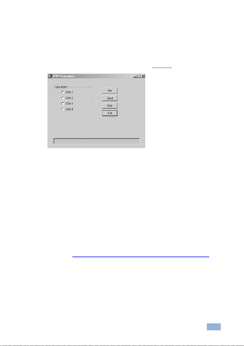
6.1.3 Upgrading the Firmware
Follow these steps to upgrade the firmware:
1. Double click the KFR-Programmer desktop icon.
The KFR-Programmer window appears (see Figure 12).
Figure 12: The KFR-Programmer Window
2. Select the required COM Port to which the FC-10ETH is connected on your
PC.
3. Press the File button to select the .s19 firmware file included in the package.
4. Press the Send button to download the file. The Send button lights red.
5. Wait until downloading is completed and the red Send button turns off.
6.2 Upgrading Version 2 Devices
To upgrade the firmware of Version 2 devices, refer to the K-Upload User Guide
available at http://www.kramerelectronics.com/support/product_downloads.asp.
Page 25

22
FC-10ETH - Technical Specifications
ETHERNET INTERFACE:
10/100BaseT Ethernet
SERIAL INTERFACES:
2 RS-232 connectors, signals: RX, TX, RTS, CTS, Ground on
9−pin D−sub ports
1 RS-485 on a detachable terminal block connector
NETWORK PROTOCOLS:
ICMP, ARP (ping), TCP, UDP
POWER CONSUMPTION:
12V DC, 140mA
DIMENSIONS:
12cm x 7.5cm x 2.5cm (4.7” x 2.95” x 0.98”), W, D, H
WEIGHT:
0.3kg (0.25lbs) approx.
ACCESSORIES:
Power supply, mounting bracket
OPTIONS:
RK−3T 19" rack adapter
Specifications are subject to change without notice
Go to our Web site at http://www.kramerelectronics.com to access the list of resolutions
7 Technical Specifications
Page 26
Page 27

For the latest information on our products and a list of Kramer distributors,
visit our Web site where updates to this user manual may be found.
We welcome your questions, comments, and feedback.
Web site: www.kramerelectronics.com
E-mail: info@kramerel.com
P/N:
2900-000086
Rev:
3
!
SAFETY WARNIN G
Disconnect the unit from the power
supply before opening and servicing
 Loading...