

Page 1

Kramer Electronics, Ltd.
USER MANUAL
Models:
6410N,
6420N,
Digital to Analog Audio Converter
Analog to Digital Audio Converter
Page 2

Contents
Contents
1
Introduction 1
2
Getting Started 1
2.1 Quick Start 1
3
Overview 3
3.1 Digital Audio Inputs/Outputs on the 6410N and 6420N 3
3.2 About the 6410N 4
3.3 About the 6420N 5
3.4 Recommendations for Achieving the Best Performance 5
4
Your Audio Converters 5
4.1 Your 6410N Digital to Analog Audio Converter 6
4.1.1 The 6410N Underside 7
4.2 Your 6420N Analog to Digital Audio Converter 8
4.2.1 The 6420N Underside 9
5
Using the Audio Converters 10
5.1 Connecting the 6410N Digital to Analog Audio Converter 10
5.1.1 Using the INPUT SELECTOR Switches 11
5.2 Connecting the 6420N Analog to Digital Audio Converter 12
6
Technical Specifications 14
Figures
Figure 1: Professional and Consumer Inputs/Outputs on the 6410N / 6420N 3
Figure 2: 6410N Digital to Analog Audio Converter 6
Figure 3: 6410N Digital to Analog Audio Converter Underside 7
Figure 4: 6420N Analog to Digital Audio Converter 8
Figure 5: 6420N Analog to Digital Audio Converter Underside 9
Figure 6: Connecting the 6410N Digital to Analog Audio Converter 11
Figure 7: Connecting the 6420N Analog to Digital Audio Converter 13
Tables
Table 1: 6410N Digital to Analog Audio Converter Features 6
Table 2: Selecting the Input on the 6410N 6
Table 3: 6410N Digital to Analog Audio Converter Underside Features 7
Table 4: 6410N Input Signal and Gain 8
Table 5: 6420N Analog to Digital Audio Converter Features 8
Table 6: 6420N Analog to Digital Audio Converter Underside Features 9
Table 7: 6410N Digital to Analog Audio Converter Technical Specifications 14
Table 8: 6420N Analog to Digital Audio Converter Technical Specifications 14
i
Page 3

Introduction
1 Introduction
Welcome to Kramer Electronics! Since 1981, Kramer Electronics has been
providing a world of unique, creative, and affordable solutions to the vast
range of problems that confront the video, audio, presentation, and
broadcasting professional on a daily basis. In recent years, we have
redesigned and upgraded most of our line, making the best even better! Our
500-plus different models now appear in eight groups1 that are clearly defined
by function.
Congratulations on purchasing your Kramer DigiTOOLS 6410N Digital to
Analog Audio Converter and/or 6420N Analog to Digital Audio Converter.
These products are ideal for:
Audio broadcast and production studios
Non-linear editing studios
Multimedia and presentation format conversion
Diagnostics of audio equipment during field operation
The package includes the following items:
6410N Digital to Analog Audio Converter and/or 6420N Analog to
Digital Audio Converter
Power adapter(s)
This user manual
2 Getting Started
We recommend that you:
Unpack the equipment carefully and save the original box and packaging
materials for possible future shipment
Review the contents of this user manual2
Use Kramer high performance high resolution cables3
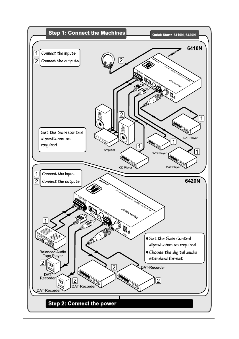
2.1 Quick Start
This quick start chart summarizes the basic setup and operation steps.
1 GROUP 1: Distribution Amplifiers; GROUP 2: Video and Audio Switchers, Matrix Switchers and Controllers; GROUP 3:
Video, Audio, VGA/XGA Processors; GROUP 4: Interfaces and Sync Processors; GROUP 5: Twisted Pair Interfaces;
GROUP 6: Accessories and Rack Adapters; GROUP 7: Scan Converters and Scalers; and GROUP 8: Cables and Connectors
2 Download up-to-date Kramer user manuals from the Internet at this URL: http://www.kramerelectronics.com
3 The complete list of Kramer cables is on our Web site at http://www.kramerelectronics.com
1
Page 4
Getting Started
2
KRAMER: SIMPLE CREATIVE TECHNOLOGY
Page 5
Overview
AES / EBU
Digital Audio Transmission Inputs/Outputs
3 Overview
Both the 6410N Digital to Analog Audio Converter and the 6420N Analog to
Digital Audio Converter use digital audio transmission standards, as section
3.1 describes.
This section summarizes:
The 6410N (see section 3.2)
The 6420N (see section 3.3)
Recommendations for achieving the best performance (see section 3.4)
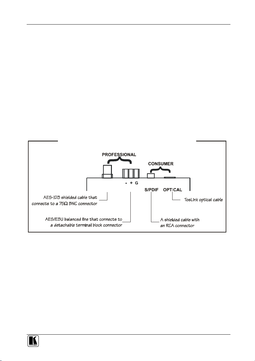
3.1 Digital Audio Inputs/Outputs on the 6410N and 6420N
Figure 1 illustrates the transmission standards for professional and consumer
formats, which can be translated via the 6410N/6420N.
AES 75
Figure 1: Professional and Consumer Inputs/Outputs on the 6410N / 6420N
3
Page 6

Overview
3.2 About the 6410N
The 6410N is a high performance format converter for digital audio signals. It
converts AES/EBU, AES-ID3, S/PDIF or Toslink® optical digital audio
signals simultaneously1 to:
Analog balanced stereo on detachable terminal block connectors
Unbalanced stereo on a 3.5” jack, capable of driving a 32 load
(headphones)
In particular, the 6410N:
Supports multi-standards - AES/EBU, IEC 958, S/PDIF and EIAJ
CP340/1201 professional and consumer formats with sampling
frequencies up to 96kHz
Provides automatic equalization and reclocking of the digital audio stream
coming from any digital input
Automatically detects the sample rate of the digital input, ranging from
32kHz to 96kHz
Features selectable conversion ratio (D/A) settings: 0dBFS to +12dB,
+16dB, +20dB or +24dB
Has an S/N Ratio of over 88dB
Has AES/EBU and AES-ID3 transformer coupled inputs
The 6410N is 12VDC fed and is housed in a DigiTOOLS enclosure.
1 As Figure 6 illustrates, the sound outputs from both the amplifier and the headphones simultaneously
4
KRAMER: SIMPLE CREATIVE TECHNOLOGY
Page 7

Your Audio Converters
3.3 About the 6420N
The 6420N is a high performance format converter for balanced audio
signals. It converts two channels of balanced audio signals to AES/EBU,
AES-ID3, S/PDIF and TOSlink® optical digital outputs simultaneously.
In particular, the 6420N:
Supports multi-standards - AES/EBU, IEC 958, S/PDIF and EIAJ
CP340/1201 professional and consumer formats with sampling
frequencies up to 96kHz
With its analog balanced stereo audio input signal, splits to four digital
audio output signals1, available in all the possible digital audio interfaces
Features selectable sampling frequencies of 32k, 44.1k, 48k, or 96k
Features selectable gain ratio (A/D) settings: -12dB, -16dB, -20dB or -24dB
to 0dBFs
Features selectable digital audio system bits (professional or consumer)
Has AES/EBU and AES-ID3 transformer coupled outputs
The 6420N is 12VDC fed and is housed in a DigiTOOLS enclosure.
3.4 Recommendations for Achieving the Best Performance
To achieve the best performance:
Connect only good quality connection cables, thus avoiding interference,
deterioration in signal quality due to poor matching, and elevated noiselevels (often associated with low quality cables)
Avoid interference from neighboring electrical appliances and position your
Kramer 6410N/6420N away from moisture, excessive sunlight and dust
Caution – No operator-serviceable parts inside unit.
Warning – Use only the Kramer Electronics input power
wall adapter that is provided with this unit2.
Warning – Disconnect power and unplug unit from wall
before installing or removing device or servicing unit.
4 Your Audio Converters
Sections 4.1 and 4.2 define the 6410N Digital to Analog Audio Converter and
the 6420N Analog to Digital Audio Converter, respectively.
1 Functioning as a 1:4 DA
2 For example: model number AD2512C, part number 2535-000251
5
Page 8

Your Audio Converters
4.1 Your 6410N Digital to Analog Audio Converter
Figure 2 and Table 1 define the 6410N Digital to Analog Audio Converter:
Figure 2: 6410N Digital to Analog Audio Converter
Table 1: 6410N Digital to Analog Audio Converter Features
# Feature Function
1 12V DC +12V DC connector for powering the unit
2
DIGITAL
INPUTS
3 AES / EBU Detachable
4 S/PDIF RCA Connector Connect to the digital audio source
5
6 ANALOG
OUT
7 A Push Button
INPUT
SELECTOR
8
9 LINK LED Illuminates when receiving the appropriate input signal
10 VOLUME Control Knob Rotate to adjust the headphones output signal level
11 PHONES Out Connector Connects to a headphone set
12 ON LED Illuminates when receiving power
AES 75 BNC Connector
Terminal Block Connector
OPTICAL Toslink® Optical
Connector
LEFT and RIGHT
Detachable Terminal Block
Connectors
B Push Button
Connect to the digital audio source
Connect to the digital audio source
Connect to the digital audio source
Connect to the analog audio acceptor
Press A and B buttons (as detailed on side panel) to
select the input (see Table 2)
Table 2: Selecting the Input on the 6410N
Press A and press B to select:
IN IN AES/EBU
OUT IN
IN OUT S/PDIF
OUT OUT OPTICAL
6
AES 75
KRAMER: SIMPLE CREATIVE TECHNOLOGY
Page 9

Your Audio Converters
4.1.1 The 6410N Underside
Figure 3 and Table 3 define the 6410N underside:
Figure 3: 6410N Digital to Analog Audio Converter Underside
Table 3: 6410N Digital to Analog Audio Converter Underside Features
Feature Function
GAIN
CONTROL
Dipswitches
RIGHT
LEFT
Set the dipswitches as follows to determine the RIGHT channel
conversion ratio1 (GAIN CONTROL):
Gain Control: DIP 1 DIP 2 DIP 3 DIP 4
+24dB ON OFF OFF OFF
+20dB OFF ON OFF OFF
+16dB OFF OFF ON OFF
+12dB OFF OFF OFF ON
Set the dipswitches as follows to determine the LEFT channel conversion
ratio1 (GAIN CONTROL):
Gain Control: DIP 5 DIP 6 DIP 7 DIP 8
+24dB ON OFF OFF OFF
+20dB OFF ON OFF OFF
+16dB OFF OFF ON OFF
+12dB OFF OFF OFF ON
1 From digital to analog
7
Page 10

Your Audio Converters
Table 4 shows an example of the relation between the input signal, the
selected gain and the THD + N.
Table 4: 6410N Input Signal and Gain
Vinput [vrms] Gain [dB] THD + N [dB] @1kHz
1
1
1
0.7
+12 -94
+16 -95
+20 -94
+24 -90
4.2 Your 6420N Analog to Digital Audio Converter
Figure 4 and Table 5 define the 6420N Analog to Digital Audio Converter:
Figure 4: 6420N Analog to Digital Audio Converter
Table 5: 6420N Analog to Digital Audio Converter Features
# Feature Function
1 12V DC +12V DC connector for powering the unit
2
DIGITAL
OUTPUTS
3 AES / EBU Detachable
4 S/PDIF RCA Connector Connect to the digital audio acceptor
5
6 ANALOG
INPUTS
7 MODE SELECTOR Dipswitches Set a dipswitch to ON to choose the appropriate
8 ON LED Illuminates when receiving power
AES 75 BNC connector
Terminal Block Connector
OPTICAL Toslink® Optical
Connector
LEFT and RIGHT
Detachable Terminal Block
Connectors
Connect to the digital audio acceptor
Connect to the digital audio acceptor
Connect to the digital audio acceptor
Connect to the analog audio source
sample rate frequency
8
KRAMER: SIMPLE CREATIVE TECHNOLOGY
Page 11

Your Audio Converters
4.2.1 The 6420N Underside
Figure 5 and Table 6 define the 6420N underside:
Figure 5: 6420N Analog to Digital Audio Converter Underside
Table 6: 6420N Analog to Digital Audio Converter Underside Features
# Feature Function
1 PROFFESIONAL / CONSUMER
Switch
2 LEFT
GAIN CONTROL
Dipswitches
RIGHT
Set to choose the digital audio system bit
Set the dipswitches as follows to determine the LEFT
channel conversion ratio1 (GAIN CONTROL):
Gain Control: DIP 1 DIP 2 DIP 3 DIP 4
-24dB ON OFF OFF OFF
-20dB OFF ON OFF OFF
-16dB OFF OFF ON OFF
-12dB OFF OFF OFF ON
Set the dipswitches as follows to determine the RIGHT
channel conversion ratio1 (GAIN CONTROL):
Gain Control: DIP 5 DIP 6 DIP 7 DIP 8
-24dB ON OFF OFF OFF
-20dB OFF ON OFF OFF
-16dB OFF OFF ON OFF
-12dB OFF OFF OFF ON
1 From analog to digital
9
Page 12

Using the Audio Converters
5 Using the Audio Converters
Sections 5.1 and 5.2 describe how to connect the 6410N Digital to Analog
Audio Converter and the 6420N Analog to Digital Audio Converter,
respectively.
5.1 Connecting the 6410N Digital to Analog Audio Converter
To connect your 6410N Digital to Analog Audio Converter, as illustrated in
the example in Figure 6, do the following1:
1. Connect up to four sources to the four digital input connectors, as follows:
Connect an AES-75 source (for example, a DAT-Player) to the
AES-75 BNC input connector
Connect an AES/EBU source (for example, a DAT-Player) to the
AES/EBU detachable terminal block input connector using a shielded
twisted pair cable
Connect an S/PDIF source (for example, a DVD Player) to the S/PDIF
RCA input connector
Connect an optical source (for example, a CD Player) to the optical
input connector
2. Connect up to two analog acceptors, as follows:
Connect the ANALOG OUT LEFT and RIGHT detachable terminal
block connectors via shielded twisted pair cables to an analog balanced
stereo acceptor (for example, an amplifier with a pair of loudspeakers)
If required, connect the PHONES 3.5mm output jack to a headphone
set2
3. Connect the 12V DC power adapter to the power socket and connect the
adapter to the mains electricity (not shown in Figure 6).
4. Set the conversion ratio on the underside of the unit3.
1 Switch OFF the power on each device before connecting it to your 6410N. After connecting your 6410N, switch on its
power and then switch on the power on each device
2 The headphone output is usually used for diagnostics and setup of the audio system. It is recommended to disconnect the
headphones (or to minimize the headphone volume level) when not in use
3 It is essential that you choose the correct conversion ratio to prevent clipping, and to maintain the S/N ratio within the spec
limits. The selection of the conversion rate greatly depends on the type of audio played, and also on the audio equipment that
is connected to the 6410N
10
KRAMER: SIMPLE CREATIVE TECHNOLOGY
Page 13

Using the Audio Converters
Figure 6: Connecting the 6410N Digital to Analog Audio Converter
5.1.1 Using the INPUT SELECTOR Switches
Set the digital input standard by pushing in and/or releasing one or both of the
two INPUT SELECTOR switches1 on the 6410N Digital to Analog Audio
Converter, as Table 1 defines.
1 Item 7 (button A) and item 8 (button B), in Figure 2
11
Page 14

Using the Audio Converters
5.2 Connecting the 6420N Analog to Digital Audio Converter
To connect your 6420N Analog to Digital Audio Converter, as illustrated in
the example in Figure 7, do the following1:
1. Connect an analog balanced stereo source (for example, a balanced audio
tape player) to the ANALOG INPUT LEFT and RIGHT detachable
terminal block connector connectors via shielded twisted pair cables.
2. Connect the four different digital output connectors to up to four acceptors,
as follows:
Connect the AES-75 BNC output connector to an AES-75 acceptor
(for example, a DAT-Recorder)
Connect the AES/EBU detachable terminal block output connector2 to
an AES/EBU acceptor (for example, a DAT-Recorder)
Connect the S/PDIF RCA output connector to an S/PDIF acceptor (for
example, a DAT-Recorder3)
Connect the OPTICAL output connector to an optical acceptor (for
example, a DAT-Recorder3)
3. Connect the 12V DC power adapter to the power socket and connect the
adapter to the mains electricity (not shown in Figure 7).
4. Set the MODE SELECTOR dipswitches on the 6420N Analog to Digital
Audio Converter to determine the appropriate digital sampling frequency.
5. On the machine underside:
If required, set the switch to PROFESSIONAL or CONSUMER to
determine the digital audio standard format
Set the conversion ratio on the underside of the unit4
1 Switch OFF the power on each device before connecting it to your 6420N. After connecting your 6420N, switch on its
power and then switch on the power on each device
2 Using a shielded twisted pair cable (110)
3 A small-sized consumer DAT-Recorder
4 It is essential that you choose the correct conversion rate to prevent clipping and to maintain the S/N ratio within the spec
limits. The selection of the conversion rate greatly depends on the type of audio played, and also on the audio equipment that
is connected to the 6420N
12
KRAMER: SIMPLE CREATIVE TECHNOLOGY
Page 15

Using the Audio Converters
Figure 7: Connecting the 6420N Analog to Digital Audio Converter
13
Page 16

Technical Specifications
6 Technical Specifications
Table 7 and Table 8 include the technical specifications for the 6410N Digital
to Analog Audio Converter and the 6420N Analog to Digital Audio
Converter, respectively.
Table 7: 6410N Digital to Analog Audio Converter Technical Specifications
INPUTS:
OUTPUTS: 2 analog outputs: balanced line out on detachable terminal blocks;
SAMPLE RATE CONVERSION: 32kHz, 44.1kHz, 48kHz, 96kHz
CONVERSION GAIN: +12dB, +16dB, +20dB,+24dB
BANDWIDTH (+4dBu/-3dBu): 20Hz to 22kHz
MAX. OUTPUT LEVEL: 11.2Vpp @1kHz
S/N RATIO: 88dB
AUDIO THD + NOISE: -92dB
AUDIO 2nd HARMONIC: 0.003%
CONTROLS: Input selector buttons, 8 gain switches, headphones level rotary control
POWER SOURCE: 12V DC/1.25A, 150mA
DIMENSIONS: 12cm x 6.95cm x 2.44cm (4.72" x 2.74" x 0.96", W, D, H)
WEIGHT: .3kg (0.66lbs.) approx.
ACCESSORIES: Power supply, mounting bracket
OPTIONS: 19" rack adapters
Table 8: 6420N Analog to Digital Audio Converter Technical Specifications
INPUTS: 1 analog input balanced line in (10k) on detachable terminal blocks
OUTPUTS:
SAMPLE RATE CONVERSION: 32kHz, 44.1kHz, 48kHz, 96kHz
MAX. INPUT LEVEL: 11.2Vpp @1kHz
CONVERSION GAIN: -12dB, -16dB, -20dB,-24dB
CONTROLS: 4 sample rate selector switches, system bit selector switch, 8 gain switches,
COUPLING: AC
POWER SOURCE: 12V DC/1.25A, 130mA
DIMENSIONS: 12cm x 6.95cm x 2.44cm (4.72" x 2.74" x 0.96", W, D, H)
WEIGHT: .3kg (0.66lbs.) approx.
ACCESSORIES: Power supply, mounting bracket
OPTIONS: 19" rack adapters
4 digital audio inputs: AES 75; AES/EBU; S/PDIF; TosLink Optical
3.5mm headphone jack
knob, 2 LEDs: ON and LINK
4 digital audio outputs: AES 75; AES/EBU; S/PDIF; TosLink Optical
ON LED
14
KRAMER: SIMPLE CREATIVE TECHNOLOGY
Page 17

LIMI TED WARRAN TY
Kramer Electronics (hereafter ) warrants this product free from defects in material and workmanship under the
following terms.
HOW LONG IS THE WARRANT Y
Labor and parts are warranted for seven years from the date of the first customer purchase.
WHO IS PROTECT ED?
Only the first purchase customer may enforce this warranty.
WHAT IS COVERED AND WHAT IS NOT COVERED
Except as below, this warranty covers all defects in material or workmanship in this product. The following are not covered
by the warranty:
1. Any product which is not distributed by Kramer, or which is not purchased from an authorized Kramer dealer. If you are
uncertain as to whether a dealer is authorized, please contact Kramer at one of the agents listed in the Web site
www.kramerelectronics.com.
2. Any product, on which the serial number has been defaced, modified or removed, or on which the WARRANTY VOID
TAMPERED sticker has been torn,
IF reattached, removed or otherwise interfered with.
3. Damage, deterioration or malfunction resulting from:
i) Accident, misuse, abuse, neglect, fire, water, lightning or other acts of nature
ii) Product modification, or failure to follow instructions supplied with the product
iii) Repair or attempted repair by anyone not authorized by Kramer
iv) Any shipment of the product (claims must be presented to the carrier)
v) Removal or installation of the product
vi) Any other cause, which does not relate to a product defect
vii) Cartons, equipment enclosures, cables or accessories used in conjunction with the product
WHAT WE WILL PAY FOR AND WHAT WE WILL NOT PAY FOR
We will pay labor and material expenses for covered items. We will not pay for the following:
1. Removal or installations charges.
2. Costs of initial technical adjustments (set-up), including adjustment of user controls or programming. These costs are the
responsibility of the Kramer dealer from whom the product was purchased.
3. Shipping charges.
HOW YO U C AN GET WARRANTY SERVI CE
1. To obtain service on you product, you must take or ship it prepaid to any authorized Kramer service center.
2. Whenever warranty service is required, the original dated invoice (or a copy) must be presented as proof of warranty
coverage, and should be included in any shipment of the product. Please also include in any mailing a contact name,
company, address, and a description of the problem(s).
3. For the name of the nearest Kramer authorized service center, consult your authorized dealer.
LIMI TATION OF IMPLIE D WARRANT IES
All implied warranties, including warranties of merchantability and fitness for a particular purpose, are limited in duration to
the length of this warranty.
EXCLUSIO N OF DAMAGES
The liability of Kramer for any effective products is limited to the repair or replacement of the product at our option. Kramer shall
not be liable for:
1. Damage to other property caused by defects in this product, damages based upon inconvenience, loss of use of the product, loss
of time, commercial loss; or:
2. Any other damages, whether incidental, consequential or otherwise. Some countries may not allow limitations on how long an
implied warranty lasts and/or do not allow the exclusion or limitation of incidental or consequential damages, so the above
limitations and exclusions may not apply to you.
This warranty gives you specific legal rights, and you may also have other rights, which vary from place to place.
All products returned to Kramer for service must have prior approval. This may be obtained from your dealer.
NOTE:
This equipment has been tested to determine compliance with the requirements of:
EN-50081: "Electromagnetic compatibility (EMC);
Residential, commercial and light industry"
EN-50082: "Electromagnetic compatibility (EMC) generic immunity standard.
CFR-47: FCC Rules and Regulations:
CAUT ION!
generic emission standard.
Part 1:
Part 1: Residential, commercial and light industry environment".
Part 15: “Radio frequency devices
Subpart B Unintentional radiators”
Servicing the machines can only be done by an authorized Kramer technician. Any user who makes changes or
modifications to the unit without the expressed approval of the manufacturer will void user authority to operate the
equipment.
Use the supplied DC power supply to feed power to the machine.
Please use recommended interconnection cables to connect the machine to other components.
Kramer
15
Page 18

For the latest information on our products and a list of Kramer
distributors, visit our Web site: www.kramerelectronics.com,
where updates to this user manual may be found.
We welcome your questions, comments and feedback.
Safety Warning:
Disconnect the unit from the power supply before
opening/servicing.
Caution
PN:
2900-000317
Rev:
2
Kramer Electronics, Ltd.
Web site: www.kramerelectronics.com
E-mail: info@kramerel.com
P/N: 2900-000317 REV 2
 Loading...