

Page 1

KRAMER ELECTRONIC S LTD.
USER MANUAL
MODEL:
61 3T
3G HD-SDI Mini Optical
Transmitter
61 3R
3G HD-SDI Mini Optical
Receiver
P/N: 2900-000721 Rev 3
Page 2
Page 3

613T, 613R – Contents
i
Contents
1 Introduction 1
2 Getting Started 2
2.1 Achieving the Best Performance 2
2.2 Safety Instructions 3
2.3 Recycling Kramer Products 3
3 Overview 4
3.1 Defining the 613T, 613R 3G HD-SDI Mini Optical Transmitter/Receiver 5
3.2 Powering the 613T, 613R 5
4 Using the 3G-SDI Mini Optical Set 6
4.1 Connecting the 3G-SDI Mini Optical Transmitter/Receiver Set 6
4.2 Avoiding Pitfalls Using the 613T and 613R 7
5 Technical Specifications 8
Figures
Figure 1: 613T, 613R 3G HD-SDI Mini Optical Transmitter/Receiver 5
Figure 2: Power Connector Pinout 5
Page 4

613T, 613R - Introduction
1
1 Introduction
Welcome to Kramer Electronics! Since 1981, Kramer Electronics has been
providing a world of unique, creative, and affordable solutions to the vast range of
problems that confront video, audio, presentation, and broadcasting professionals
on a daily basis. In recent years, we have redesigned and upgraded most of our
line, making the best even better!
Our 1,000-plus different models now appear in 11 groups that are clearly defined
by function: GROUP 1: Distribution Amplifiers; GROUP 2: Switchers and Routers;
GROUP 3: Control Systems; GROUP 4: Format/Standards Converters; GROUP 5:
Range Extenders and Repeaters; GROUP 6: Specialty AV Products; GROUP 7:
Scan Converters and Scalers; GROUP 8: Cables and Connectors; GROUP 9:
Room Connectivity; GROUP 10: Accessories and Rack Adapters and GROUP 11:
Sierra Products.
Congratulations on purchasing your Kramer 613T, 613R 3G HD-SDI Mini Optical
Transmitter/Receiver, which is ideal for the following typical applications:
EFP (electronic field production) and ENG (electronic news gathering)
broadcasting
Stadium to studio 3G-SDI digital video extension broadcasting
Medical, military, government and security applications
Page 5

2
613T, 613R - Getting Started
Go to http://www.kramerelectronics.com to check for up-to-date
user manuals, application programs, and to check if firmware
upgrades are available (where appropriate).
This equipment is to be used only inside a building. It may only be
connected to other equipment that is installed inside a building.
i
!
2 Getting Started
We recommend that you:
Unpack the equipment carefully and save the original box and packaging
materials for possible future shipment
Review the contents of this user manual
2.1 Achieving the Best Performance
To achieve the best performance:
Use only good quality connection cables (we recommend Kramer high-
performance, high-resolution cables) to avoid interference, deterioration in
signal quality due to poor matching, and elevated noise levels (often
associated with low quality cables)
Do not secure the cables in tight bundles or roll the slack into tight coils
Avoid interference from neighboring electrical appliances that may adversely
influence signal quality
Position your Kramer 613T, 613R away from moisture, excessive sunlight
and dust
Page 6

613T, 613R - Getting Started
3
Caution:
There are no operator serviceable parts inside the unit
Warning:
Use only the Kramer Electronics input power wall
adapter that is provided with the unit
Warning:
Disconnect the power and unplug the unit from the wall
before installing
!
2.2 Safety Instructions
2.3 Recycling Kramer Products
The Waste Electrical and Electronic Equipment (WEEE) Directive 2002/96/EC
aims to reduce the amount of WEEE sent for disposal to landfill or incineration by
requiring it to be collected and recycled. To comply with the WEEE Directive,
Kramer Electronics has made arrangements with the European Advanced
Recycling Network (EARN) and will cover any costs of treatment, recycling and
recovery of waste Kramer Electronics branded equipment on arrival at the EARN
facility. For details of Kramer’s recycling arrangements in your particular country
go to our recycling pages at http://www.kramerelectronics.com/support/recycling/.
Page 7

4
613T, 613R - Overview
3 Overview
The 613T converts 3G-SDI, HD-SDI and DVB-ASI (Digital Video Broadcasting –
Asynchronous Serial Interface) digital video signals to optical signals. It transmits
them over single mode fiber optic cable to the 613R that decodes the optical
signals back to electrical 3G-SDI, HD-SDI and DVB-ASI digital video signals.
The 613T and 613R transmitter/receiver pair:
Supports up to 3G-SDI digital video signals over fiber optic cable
Supports 1080p, 3G-SDI format
Is designed to transport one-channel SMPTE-424M 3G-SDI, SMPTE 292M
HD-SDI or SMPTE-259M serial digital video signal over long distance
through single-mode optical fiber
Features signal equalizing and re-clocking
Has a transmission range of up to 19 miles (30 km) at 3Gbps
Handles SDI, DVB-ASI, HD-SDI, 3G-SDI
Includes a latch locking mechanism for the power supply to prevent the
power from disconnecting due to misuse
Includes power and status blue LEDs
Does not require any special memory size, CPU speed and chipsets, when
using a computer
Both the 613T and 613R come in a very small standalone, metal die-cast
enclosure suitable for rugged applications.
Page 8

613T, 613R - Overview
5
3.1 Defining the 613T, 613R 3G HD-SDI Mini Optical Transmitter/Receiver
This section defines the 613T, 613R.
Figure 1: 613T, 613R 3G HD-SDI Mini Optical Transmitter/Receiver
3.2 Powering the 613T, 613R
Your 613T/613R pair comes with two 5V DC power adapters. Both units need to
be connected to their external power adapter. Figure 2 illustrates the power
connector pinout:
Figure 2: Power Connector Pinout
Page 9

6
613T, 613R - Using the 3G-SDI Mini Optical Set
4 Using the 3G-SDI Mini Optical Set
This section describes how to:
Connect the detachable optical 3G-SDI Mini Optical Transmitter/ Receiver
(see Section 4.1)
Avoid pitfalls when using the 613T and 613R (see Section 4.2)
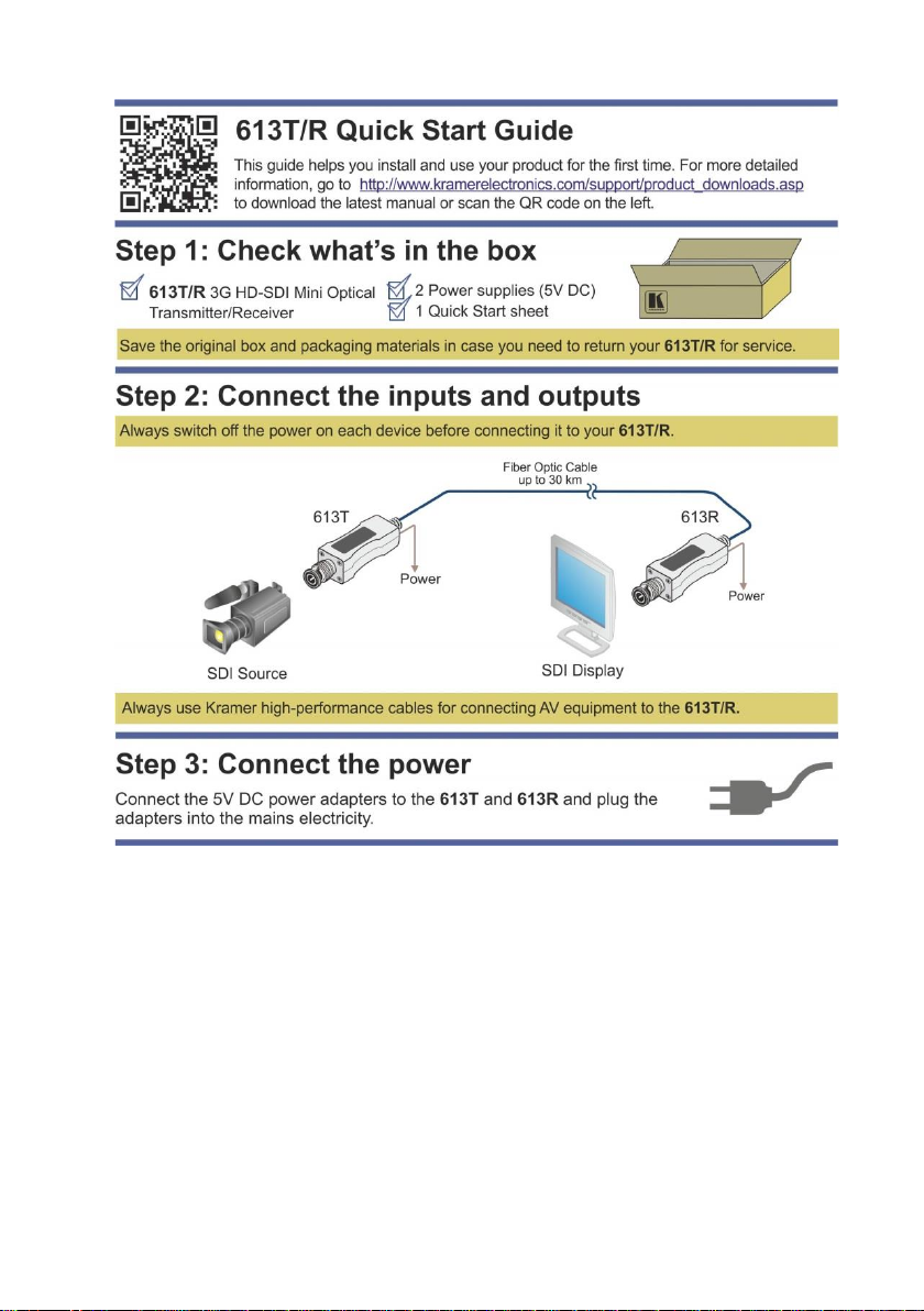
4.1 Connecting the 3G-SDI Mini Optical Transmitter/Receiver Set
To connect the 613T 3G-SDI Mini Optical Transmitter with the 613R 3G-SDI Mini
Optical Receiver, as the example in Figure 1 illustrates, do the following:
1. Connect the BNC connector of the SDI Source (for example, a camera)
directly to the 613T BNC connector.
Avoid using any intermediate cable which may result in signal quality deterioration.
2. Plug the 5V power adapters to the transmitter and to the receiver, and
connect the adapters to the mains electricity.
The blue LED lights.
3. Connect the 613R BNC connector directly to the BNC connector of the display
device.
4. Remove the protective cover from the optic fiber ST connector on the 613T
and connect to the fiber optic cable.
Use glass single-mode fiber optic cable with 1310, 1550nm bandwidth on ST
connectors.
5. Remove the protective cover from the optic fiber ST connector on the 613R
and connect to the other side of the fiber optic cable.
6. Turn ON the power on the source and the display devices.
Page 10

613T, 613R - Using the 3G-SDI Mini Optical Set
7
Caution:
Be sure that the fiber optic cables are always stored
and used away from liquid or dirt
!
4.2 Avoiding Pitfalls Using the 613T and 613R
If any of these problems occur, we recommend the following solutions:
If the display device shows only a black screen:
Make sure that all the AC and DC plugs and jacks used by the external
power supplies are firmly connected
Be sure that the BNC connectors are firmly plugged into the SDI source and the
display devices, and be sure that the transmitter and receiver modules are
correctly plugged into the source and SDI display devices, respectively
Check if the SDI source and display are powered ON and properly booted
Reset the system by unplugging and then replugging the transmitter SDI port
or receiver SDI port and then reboot the system
If the picture on the screen appears distorted or displays noise, check the quality
of the SDI source and the length of the optical fiber cable.
Page 11

8
613T, 613R - Technical Specifications
INPUTS:
613T: SD/HD/3G HD-SDI on a 75Ω BNC connector
613R: 1 optical ST connector
OUTPUTS:
613T: 1 optical ST connector
613R: SD/HD/3G HD-SDI on a 75Ω BNC connector
MAXIMUM DATA RATE:
Up to 3Gbps
MAXIMUM LENGTH:
30km (19mi) @3G, 1080p 3G-SDI format
FORMAT:
SMPTE 424M: 3G HD-SDI; SMPTE 292M: HD-SDI;
SMPTE 259: SDI, DVB-ASI
RECOMMENDED
FIBER-OPTIC CABLE:
1310, 1550nm single-mode optical fiber with ST
connectors
POWER CONSUMPTION:
5V DC, 1.5A
OPERATING TEMPERATURE:
-20° to 70°C (-4° to 158°F)
STORAGE TEMPERATURE:
-30° to 85°C (-22° to 185°F) ambient
HUMIDITY:
5% to 95% RH
DIMENSIONS:
1.9cm x 8.3cm x 1.0 cm (0.7" x 3.3" x 0.7") W, D, H
WEIGHT:
613T and 613R 0.1kg (0.2lbs) approx.
ACCESSORIES:
2 power supplies
Specifications are subject to change without notice at http://www.kramerelectronics.com
5 Technical Specifications
Page 12

Page 13

For the latest information on our products and a list of Kramer distributors,
visit our Web site where updates to this user manual may be found.
We welcome your questions, comments, and feedback.
Web site: www.kramerelectronics.com
E-mail: info@kramerel.com
P/N:
2900-000721
Rev:
3
!
SAFETY WARNIN G
Disconnect the unit from the power
supply before opening and servicing
 Loading...