How it Works
Log In / Sign Up
Buy Points
How it Works
FAQ
Contact Us
Questions and Suggestions
Users
Kramer
Loading...
W
WD-MF
WHC-3
WP-110
4
WP-110xl
WP-120
2
WP-121
2
wp-20
5
WP-209
WP-20-BLNK
WP-20CT
2
WP-20CT EU PANEL SET
WP-20/US(W)
2
WP-210
WP-210A
WP-210AE
WP-210AL
WP-210E
WP-211DS
WP-211T
2
WP-211T EU PANEL SET
WP-211X
WP-211X EU PANEL SET
WP-220
WP-220E
WP-230
WP-27
WP-28
WP-2UC
WP-2UT/R-KIT
WP-2UT US PANEL SET
WP-301xl
WP-3H2
WP-3H2 PANEL SET
WP-3TB
WP-4 iR
2
WP-500
WP-501
WP-561
WP-562
2
WP-571
WP-572
WP-577VH
WP-580R
3
WP-580RXR
3
WP-580T
WP-580T/US/D(B)
WP-580TXR
3
WP-5VH2
3
WP-789R
WP-789R US PANEL SET
WP-789T
3
WP-871xr
4
WP-871XR/US
WP-872xr
2
WP-872xr EU PANEL SET
WP-DEC7
2
WP-DEC7 EU PANEL SET
WP-EN6
2
WP-EN6 US PANEL SET
WP-HDMI1M
WP-HDMI2M
WPN-11
WPN-12
WP-SW2-EN7
2
WP-SW2-EN7 EU PANEL SET
WR45
WRR
WSI-1VGA
WSP-1
WU3-AA
WU-AA
WU-AB
WU-BA
WU-BB
WU-CA
WU-CC
WV-11
WV-12
WV-20
WVS-1
WVS-2
WX-1
WX-2F
WX-2M
WXA-1
WXA-1/U(G)
WXA-2
WXA-2P
WXA-H
WXA-H1
WXA-HU
WX-F5B
WX-FM
WXL
WXL-1F
WXL-1FM
WXL-1M
WXL-2F
WXL-2M
WX-MF
Loading...
Loading...
Nothing found
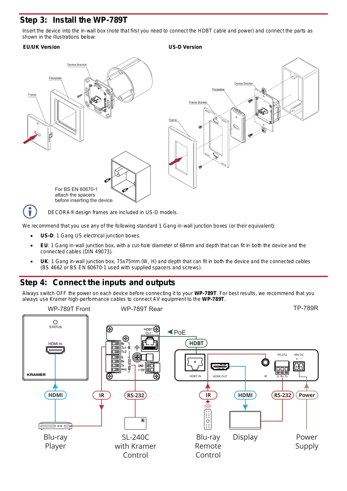
WP-789T
Datasheet
4 pgs
489.94 Kb
0
Quick Start Guide
4 pgs
1.02 Mb
0
Users Guide
27 pgs
1.75 Mb
0
Table of contents
Loading...
Kramer WP-789T Quick Start Guide
...
Kramer Quick Start Guide
Download
Specifications and Main Features
Frequently Asked Questions
User Manual
Download
Page 1
Page 2
Page 3
Page 4
Loading...
+
hidden pages
Unhide
You need points to download manuals.
1 point = 1 manual.
You can buy points or you can get point for every manual you upload.
Buy points
Upload your manuals
 Loading...