

Page 1

KRAMER ELECTRONICS LTD.
USER MANUAL
MODELS:
WP
HDMI Line Transmitter
WP
HDMI Line Receiver
P/N: 2900-300094 Rev 5
-580T
-580R
Page 2
Page 3

Contents
1 Introduction 1
2 Getting Started 2
2.1 Achieving the Best Performance 2
2.2 Safety Instruc tions 2
2.3 Recycling Kramer Products 3
3 Overview 4
3.1 About HDBaseT™ Technology 5
3.2 Using Twisted Pair Cable 5
4 Defining the WP-580T HDMI Line Transmitter 6
5 Defining the WP-580R HDMI Line Receiver 8
6 Connecting the WP-580T Transmitter to the WP-580R Receiver 10
6.1 Wiring the TP LINE IN / LINE OUT RJ-45 Connectors 12
6.2 Grounding the Transmitter/Receiver 13
7 Technical Specifications 14
Figures
Figure 1: WP-580T HDMI Line Transmitter for the US and US-D Sizes 6
Figure 2: WP-580T HDMI Line Transmitter for Europe (80mm/86mm) 7
Figure 3: WP-580R HDMI Line Receiver for the US and US-D S izes 8
Figure 4: WP-580R HDMI Line Receiver for Europe (80mm/86mm) 9
Figure 5: Connecting the WP-580T/WP-580R Transmitter/Receiver 11
Figure 6: TP PINOUT 12
Figure 7: Grounding Connection Components 13
WP-580T/WP-580R – Contents i
Page 4

i
1 Introduction
Welcome to Kramer Electronics! Since 1981, Kramer Electronics has been
providing a world of unique, creative, and affordable solutions to the vast range of
problems that confront video, audio, presentation, and broadcasting professionals
on a daily basis. In recent years, we have redesigned and upgraded most of our
line, making the best even better!
Our 1,000-plus different models now appear in 13 groups that are clearly defined
by function: GROUP 1: Distribution Amplifiers; GROUP 2: Switchers and Routers;
GROUP 3: Control Systems; GROUP 4: Format/Standards Converters; GROUP
5: Range Extenders and Repeaters; GROUP 6: Specialty AV Products; GROUP
7: Scan Converters and Scalers; GROUP 8: Cables and Connectors; GROUP 9:
Room Connectivity; GROUP 10: Accessories and Rack Adapters; GROUP 11:
Sierra Video Products; GROUP 12: Digital Signage; and GROUP 13: Audio.
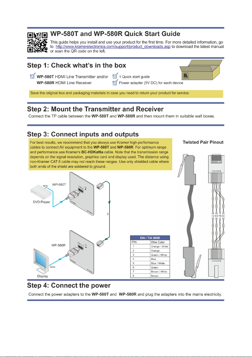
Congratulations on purchasing your Kramer WP-580T transmitter and/or
WP-580R receiver (for the US, Europe and/or US-D wall plates), which c an be
part of a transmitter/receiver system and is ideal for the following typical
applications:
• Conference rooms, boardrooms, auditoriums, hotels, churches, classrooms
and production studios
• Rental and staging
Note that WP-580T and WP-580R are purchased separately, and
can be connected to other HDBaseT certified transmitters and
receivers, respectively.
WP-580T/WP-580R - Introduction 1
Page 5

i
!
!
2 Getting Started
We recommend that you:
• Unpack the equipment carefully and save the original box and packaging
materials for possible future shipment
• Review the contents of this user manual
Go to www.kramerav.com/manual/WP-580T to check for up-to-date user
manuals, application programs, and to check if firmware upgrades are
available (where appropriate).
2.1 Achieving the Best Performance
To achieve the best performance:
• Use only good quality connection cables (we recommend Kramer high-
performance, high-resolution cables) to avoid interference, deterioration in
signal quality due to poor matching, and elevated noise levels (often
associated with low quality cables)
• Do not secure the cables in tight bundles or roll the slack into tight coils
• Avoid interference from neighboring electrical appliances that may adversely
influence signal quality
• Position your Kramer WP-580T transmitter and WP-580R receiver away
from moisture, excessive sunlight and dust
This equipment is to be used only inside a building. It may only be
connected to other equipment that is installed inside a building.
2.2 Safety Instructions
Caution: There are no operator serviceable parts inside the unit
Warning:
Warning:
2 WP-580T/WP-580R - Getting Started
Use only the Kramer Electronics input power wall
adapter that is provided with the unit
Disconnect the power and unplug the unit from the
wall before installing
Page 6

2.3 Recycling Kramer Products
The Waste Electrical and Electronic Equipment (WEEE) Directive 2002/96/EC
aims to reduce the amount of WEEE sent for disposal to landfill or incineration by
requiring it to be collected and recycled. To comply with the WEEE Directive,
Kramer Electronics has made arrangements with the European Advanced
Recycling Network (EARN) and will cover any costs of treatment, recycling and
recovery of waste Kramer Electronics branded equipment on arrival at the EARN
facility. For details of Kramer’s recycling arrangements in your particular country
go to our recycling pages at www.kramerav.com/support/recycling/
.
WP-580T/WP-580R - Getting Started 3
Page 7

non−Kramer CAT 6 cable may not reach these ranges.
i
3 Overview
The WP-580T and WP-580R are a high-performance, HDBaseT technology
Twisted Pair transmitter and receiver for HDMI signals. The WP-580T converts the
HDMI signal to a twisted pair signal. The WP-580R converts the twisted pair signal
back into an HDMI signal.
The WP-580T and the WP-580R can form a transmission and reception system
either together or each device separately with another certified HDBaseT device.
For example, the transmitter and receiver system can be composed of the
WP-580T that connects to the Kramer TP-580R to form a transmitter receiver pair.
The WP-580T transmitter and WP-580R receiver feature:
• A bandwidth of up to 10.2Gbps (3.4Gbps per graphic channel), supporting
2K resolution
• System Range - Up to 70 meters (230 feet)
• HDBaseT technology
• HDTV compatibility and HDCP compliance
• HDMI support - HDMI (deep color, x.v.Color™, lip sync, HDMI
uncompressed audio channels, Dolby TrueHD, DTS−HD, CEC, 2K, 3D)
• EDID pass-through - passes EDID signals from the source to the display
• LED status indicators for power
• Wall plate size of 2 gang EU/US/US-D
For optimum range and performance using HDBaseT™, use Kramer's
BC−HDKat6a cable. Note that the transmission range depends on
the signal resolution, source and display used. The distance using
4 WP-580T/WP-580R - Overview
Page 8

i
3.1 About HDBaseT™ Technology
HDBaseT™ is an advanced all-in-one connectivity technology (Supported by the
HDBaseT Alliance). It is particularly suitable in the consumer home environment
as a digital home networking alternative where it enables you to replace numerous
cables and connectors by a single LAN cable used to transmit, for example,
uncompressed full high-definiti on video, audio, IR, as well as various control
signals.
The products described in this user manual are HDBaseT certified.
3.2 Using Twisted Pair Cable
Kramer engineers have developed special twisted pair cables to best match our
digital twisted pair products; the Kramer
significantly outperforms regular CAT 5 / CAT 6 cables.
BC−HDKat6a (CAT 6 23 AWG cable)
WP-580T/WP-580R - Overview 5
Page 9

i
4 Defining the WP-580T HDMI Line Transmitter
Figure 1: WP-580T HDMI Line Transmitter for the US and US-D Sizes
Note that the US-D wall plate is supplied with a Midway Size 2 gang
DECORA
DECORA
Oversized.
DECORA® is a registered trademark of Leviton Manufacturing Co ., In c.
6 WP-580T/WP-580R - Defining the WP-580T HDMI Line Transmitter
®
design frame. You can also fit it into a different sized
®
design frame (not supplied) such as Standard Size or
Page 10

#
Feature
Function
1
HDMI IN Connector
Connects to the HDMI source
3
HDBT OUT/LINE OUT
Connects to the HDBT IN/LINE IN RJ-45 connector on
WP-580R
4
5V DC
+5V DC connector for powering the unit
5
PROG 4-pin Connector
For internal use
6
Groundin g Screw
Connect to grounding wire, see Section 6.2
Figure 2: WP-580T HDMI Line Transmitter for Euro pe (80mm/86mm)
2 ON LED Lights red when only the power is connected; orange
RJ-45 Connector
WP-580T/WP-580R - Defining the WP-580T HDMI Line Transmitter 7
when the power and the input only are connected; and
green when the power and both the input and output are
connected
Note, if no input is connected the device invokes the
power save mode automatically turning off the power
the
Page 11

DECORA® is a registered trademark of Leviton Manufacturing Co ., In c.
i
5 Defining the WP-580R HDMI Line Receiver
Figure 3: WP-580R HDMI Line Receiver for the US and US-D Sizes
Note that the US-D wall plate is supplied with a Midway Size 2 gang
DECORA
DECORA
Oversized.
8 WP-580T/WP-580R - Defining the WP-580R HDMI Line Receiver
®
design frame. You can also fit it into a different sized
®
design frame (not supplied) such as Standard Size or
Page 12

#
Feature
Function
1
HDMI OUT Connector
Connects to the HDMI acceptor
2
ON LED
Lights red when the power is connected or t he power and
power save mode automatically turning off the power
3
HDBT IN/LINE IN RJ-45
Connector
Connects to the HDBT OUT/LINE OUT RJ-45 connector
on the WP-580T
4
+5V DC
+5V DC connector for powering the unit
5
PROGRAM 4-pin
For internal use
Figure 4: WP-580R HDMI Line Receiver for Europe (80mm/86mm)
Connector
6 Groundin g Screw
(optional)
WP-580T/WP-580R - Defining the WP-580R HDMI Line Receiver 9
output are connected; orange when the power and the
input only are connected; and green when the power and
both the input and output are connected
Note, if no input is connected the device invokes the
Connect to grounding wire, see Section 6.2 (for European
versions only)
Page 13

!
6 Connecting the WP-580T Transmitter to the
WP-580R Receiver
Always switch off the power to each device before connecting it to your
transmitter and receiver. After connecting your transmitter and
receiver, connect their power and then switch on the power to each
device.
You can use the WP-580T HDMI Line Transmitter and the WP-580R HDMI Line
Receiver to configure an HDMI transmitter/receiver system, as illustrated in the
example in Figure 5
To connect the WP-580T:
1. Connect the HDMI source (for example, a DVD player) to the HDMI IN
connector.
2. Connect the LINE OUT RJ-45 connector over twisted pair to the
WP-580R LINE IN connector.
Alternatively, you can use an y other c er tifi ed HD BaseT receiver device (for example, the
Kramer TP-580R)
3. Connect the 5V DC power adapter to the power socket and connect the
adapter to the mains electricity (not shown in Figure 5
To connect the WP-580R:
.
).
4. Connect the HDMI OUT connector to the HDMI acceptor (for example, a
display).
5. Connect the LINE IN RJ-45 connector over twisted pair to the
WP-580T LINE OUT connector.
Alternatively, you can use an y other c er tifi ed HD BaseT transmitter device (for example,
the Kramer TP-580T)
6. Connect the 5V DC power adapter to the power socket and connect the
adapter to the mains electricity (not shown in Figure 5
10 WP-580T/WP-580R - Connecting the WP-580T Transmitter to the WP-580R Receiver
).
Page 14

Figure 5: Connecting the WP-580T/WP-580R Transmitter/Receiver
WP-580T/WP-580R - Connecting the WP-580T Transmitter to the WP-580R Receiver 11
Page 15

Figure 6: TP PINOUT
PIN
Wire Color
1
Orange / White
2
Orange
3
Green / White
4
Blue 5 Blue / White
6
Green
7
Brown / White
8
Brown
6.1 Wiring the TP LINE IN / LINE OUT RJ-45 Connectors
This section defines the TP pinout, using a straight pin-to-pin cable with RJ-45
connectors.
EIA /TIA 568B
12 WP-580T/WP-580R - Connecting the WP-580T Transmitter to the WP-580R Receiver
Page 16

#
Component Description
1
M3X6 screw
2
1/8" Toothed Lock Washer
3
M3 Ring Tongue Terminal
6.2 Grounding the Transmitter/Receiver
The grounding screw is used to earth the chassis of the unit to the building ground
preventing static electricity from impacting the performance of the unit.
Figure 7
defines the grounding screw components.
Figure 7: Grounding Connection Component s
To ground the room controller:
1. Connect the Ring Tongue terminal to the building grounding point wire (it is
recommended to use a green-yellow AWG#18 (0.82mm
2
) wire, crimped with
a proper hand-tool).
2. Insert the M3x6 screw through the toothed lock washers and the tongue
terminal in the order shown above.
3. Insert the M3x6 screw (with the two toothed lock washers and ring tongue
terminal) into the grounding screw hole and tighten the screw.
WP-580T/WP-580R - Connecting the WP-580T Transmitter to the WP-580R Receiver 13
Page 17

WP-580T
WP-580R
INPUTS:
1 HDMI connector
1 RJ-45 connector
OUTPUTS:
1 RJ-45 connector
1 HDMI connector
BANDWIDTH:
Supports up to 3.4Gbps bandwid th pe r gra phi c channel
COMPLIANCE WITH HDMI
STANDARD:
Supports HDMI and HDCP
POWER SOURCE:
5V DC, 360mA
5V DC, 930mA
STORAGE TEMPERATURE:
-40° to +70°C (-40° to 158°F)
HUMIDITY:
10% to 90%, RHL non-condensing
DIMENSIONS:
2 gang for the USA: 11.4cm x 2.6cm x 11.4cm (4.49" x
12.4cm (4.95” x 1” x 4.88”), W, D, H
WEIGHT:
0.6kg (1.4lbs)
INCLUDED ACCESSORIES:
Power supply
OPTIONS:
Kramer BC−HDKat6a cable
Go to our Web site at www.kramerav.com to access the list of resolutions
7 Technical Specifications
OPERATING TEMPERATURE: 0° to +40°C (32° to 104°F)
1.02" x 4.49", W, D, H)
2 gang for Europe: 15.2cm x 1.9cm x 8.6cm (5.98" x
0.75" x 3.39", W, D, H)
2 gang (Midway Size) for US-D: 12.6cm x 2.5cm x
Specifications are s ub ject to cha nge without notice
14 WP-580T/WP-580R - Technical Specifications
Page 18

Page 19

For the latest information on our products and a list of Kramer distributors,
visit our Web site where updates to this user manual may be found.
P/N:
2900-300094
Rev:
5
!
SAFETY WARNING
Disconnect the unit from the power
supply before opening and servicing
We welcome your questions, comments, and feedback.
Web site: www.kramerav.com
E-mail: info@kramerav.com
 Loading...