

Page 1

USER MANUAL
MODEL:
WP-20
Wall Plate
P/N: 2900-300386 Rev 1
www.kramerAV.com
Page 2
Page 3
Page 4

WP-20 – Contents
i
Contents
1 Introduction 1
2 Getting Started 2
2.1 Achieving the Best Performance 2
2.2 Safety Instructions DC 2
2.3 Shielded Twisted Pair/Unshielded Twisted Pair 3
2.4 Recycling Kramer Products 3
3 Overview 4
3.1 About HDBaseT™ Technology 5
4 Defining the WP-20 Wall Plate 6
5 Connecting the WP-20 9
5.1 Connecting the Remote Control Switches 11
6 Principles of Operation 12
6.1 Input Selection 12
6.2 Signal Loss and Unplugged Cable Timeouts 13
6.3 Audio Signal Control 13
6.4 VGA Phase Shift 14
7 Operating the WP-20 15
7.1 Selecting an Input Manually 15
7.2 Locking the EDID 15
7.3 Resetting the WP-20 15
7.4 Analog Audio Output Volume Control 16
8 Configuring the WP-20 17
8.1 Setting the Configuration DIP-switch 17
8.2 Video Switching Timeouts 18
9 Operating the WP-20 Remotely Using the Embedded Web Pages 19
9.1 Browsing the WP-20 Web Pages 19
9.2 The Switching Page 23
9.3 The Device Settings Page 23
9.4 The Video and Audio Settings Page 26
9.5 The Authentication Page 27
9.6 The EDID Page 28
9.7 The About Us Page 30
10 Wiring the Twisted Pair RJ-45 Connectors 31
11 Technical Specifications 32
11.1 Default IP Parameters 33
11.2 Default Logon Credentials 33
11.3 Supported Resolutions 33
12 Default EDID 35
12.1 HDMI 35
12.2 PC-UXGA 37
13 Protocol 3000 38
13.1 Kramer Protocol 3000 Syntax 38
13.2 Kramer Protocol 3000 Commands 41
Page 5

ii
WP-20 - Contents
Figures
Figure 1: WP-20 Wall Plate Front Panel 6
Figure 2: WP-20E Wall Plate Front Panel 6
Figure 3: WP-20 Wall Plate Rear Panel 8
Figure 4: WP-20E Wall Plate Rear Panel 8
Figure 5: WP-20 Wall Plate Rear Panel 8
Figure 6: Connecting the WP-20 Wall Plate 9
Figure 7: Remote Switches Terminal Block 11
Figure 8: The Configuration DIP-switch 17
Figure 9: Entering Logon Credentials 19
Figure 10: The Default Page 20
Figure 11: The Main Switching Page 21
Figure 12: The Switching Page 23
Figure 13: The Device Settings Page 24
Figure 14: The Video and Audio Settings Page 26
Figure 15: The Authentication Page 27
Figure 16: The EDID Page 29
Figure 17: The About Us Page 30
Figure 18: TP Pinout Wiring 31
Page 6

WP-20 – Introduction
1
1 Introduction
Welcome to Kramer Electronics! Since 1981, Kramer Electronics has been
providing a world of unique, creative, and affordable solutions to the vast range of
problems that confront video, audio, presentation, and broadcasting professionals
on a daily basis. In recent years, we have redesigned and upgraded most of our
line, making the best even better!
Our 1,000-plus different models now appear in 14 groups that are clearly defined by
function: GROUP 1: Distribution Amplifiers; GROUP 2: Switchers and Routers;
GROUP 3: Control Systems; GROUP 4: Format/Standards Converters; GROUP 5:
Range Extenders and Repeaters; GROUP 6: Specialty AV Products; GROUP 7:
Scan Converters and Scalers; GROUP 8: Cables and Connectors; GROUP 9:
Room Connectivity; GROUP 10: Accessories and Rack Adapters; GROUP 11:
Sierra Video Products; GROUP 12: Digital Signage; GROUP 13: Audio; and
GROUP 14: Collaboration.
Congratulations on purchasing your Kramer WP-20 Wall Plate. This product, which
incorporates HDMI™ technology, is ideal for:
Display systems requiring simple, automatic input selection
Multimedia and presentation source selection
Video distribution in hotel rooms and schools
Note: All references in this manual to the WP-20 in this manual also apply to the
WP-20E European versions.
Page 7

2
WP-20 - Getting Started
Go to www.kramerav.com/downloads/WP-20 to check for up-to-date user
manuals, application programs, and to check if firmware upgrades are
available (where appropriate).
This equipment is to be used only inside a building. It may only be
connected to other equipment that is installed inside a building.
Caution:
There are no operator serviceable parts inside the unit
Warning:
Use only the Kramer Electronics power supply that is
provided with the unit
Warning:
Disconnect the power and unplug the unit from the wall
before installing
2 Getting Started
We recommend that you:
Unpack the equipment carefully and save the original box and packaging
materials for possible future shipment
Review the contents of this user manual
2.1 Achieving the Best Performance
To achieve the best performance:
Use only good quality connection cables (we recommend Kramer high-
performance, high-resolution cables) to avoid interference, deterioration in
signal quality due to poor matching, and elevated noise levels (often associated
with low quality cables)
Do not secure the cables in tight bundles or roll the slack into tight coils
Avoid interference from neighbouring electrical appliances that may adversely
influence signal quality
Position your WP-20 away from moisture, excessive sunlight and dust
2.2 Safety Instructions DC
Page 8

WP-20 – Getting Started
3
2.3 Shielded Twisted Pair/Unshielded Twisted Pair
Kramer engineers have developed special twisted pair cables to best match our
digital twisted pair products; the Kramer BC-HDKat6a (CAT 6 23 AWG) HDBaseT
certified, and the Kramer BC-DGKat7a23 (CAT 7a 23 AWG) cables. These
specially built cables significantly outperform regular CAT 6 and CAT 7a cables.
2.4 Recycling Kramer Products
The Waste Electrical and Electronic Equipment (WEEE) Directive 2002/96/EC aims
to reduce the amount of WEEE sent for disposal to landfill or incineration by
requiring it to be collected and recycled. To comply with the WEEE Directive,
Kramer Electronics has made arrangements with the European Advanced
Recycling Network (EARN) and will cover any costs of treatment, recycling and
recovery of waste Kramer Electronics branded equipment on arrival at the EARN
facility. For details of Kramer’s recycling arrangements in your particular country go
to our recycling pages at http://www.kramerelectronics.com/support/recycling/.
Page 9

4
WP-20 - Overview
For optimum range and performance, use Kramer's BC−HDKat6a and
BC−DGKat7a23 shielded twisted pair (STP) cables. Note that the
transmission range depends on the signal resolution, graphics card and
display used. The distance using non-Kramer CAT 5, CAT 6, and CAT 7
cables may not reach these ranges.
3 Overview
The WP-20 accepts an HDMI and PC graphics video input, an Ethernet signal,
serial data, and an unbalanced stereo audio input (which is embedded into the
output signal), and transmits the signal via HDBaseT (Twisted Pair) cable to a
compatible receiver (for example, the TP-588D or the TP-580RXR). The
WP-20 is a PoE (Power over Ethernet) receiver and can be powered by a
compatible PoE provider, (for example, the PSE-1).
The WP-20 supports a range of up to 130m (430ft) at normal mode (2K), up to
100m at normal mode (4K UHD); up to 180m (590ft) ultra mode (1080p @60Hz
@24bpp) when using BC−HDKat6a cables.
In particular the WP-20 features:
Support for 4K UHD, (data rate of up to 10.2Gbps)
Automatic input selection based on priority selection or last connected input
Manual input selection
Automatic live input detection based on video clock presence
Automatic analog audio detection and embedding
Power over Ethernet (PoE) which passes electrical power along with data over
Ethernet cabling. This allows a single cable to provide both data connection
and electrical power to compatible devices
Control via Kramer Protocol 3000 and embedded Web pages over a LAN
HDTV support
HDMI with Deep Color, x.v.Color™ and 3D
HDCP compliancy—works with sources that support HDCP repeater mode
Page 10

WP-20 – Overview
5
The products described in this user manual are HDBaseT certified.
I-EDIDPro™ Kramer Intelligent EDID Processing™ – Intelligent EDID handling
& processing algorithm ensures Plug and Play operation for HDMI systems
A lockable EDID
Remote control via contact-closure switches
Equalization and reclocking of the data
Support for digital audio formats
Availability in US and European versions
3.1 About HDBaseT™ Technology
HDBaseT™ is an advanced, all-in-one connectivity technology (supported by the
HDBaseT Alliance). It is particularly suitable in the ProAV – and also the home –
environment as a digital networking alternative, where it enables you to replace
numerous cables and connectors by a single LAN cable used to transmit, for
example, uncompressed, full high-definition video, audio, IR, as well as various
control signals.
Page 11
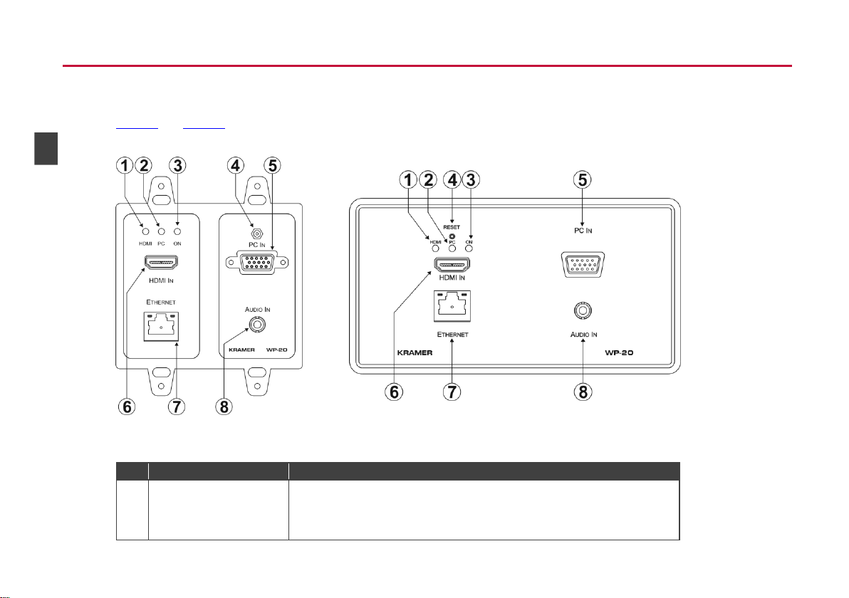
Figure 1: WP-20 Wall Plate Front Panel
Figure 2: WP-20E Wall Plate Front Panel
#
Feature
Function
1
HDMI LED
When HDMI is selected:
Lights orange when external audio is selected
Lights green when embedded audio is selected
When HDMI is not selected the LED does not light
WP-20 – Defining the WP-20 Wall Plate
4 Defining the WP-20 Wall Plate
Figure 1 and Figure 2 define the front panels of the WP-20 and the WP-20E.
6
Page 12

WP-20 – Defining the WP-20 Wall Plate
7
2
PC Graphics LED
When PC input is selected:
Lights orange when external audio is selected.
Lights green when there is no audio
When the PC input is not selected the LED does not light
3
ON LED
The LED indicates the following:
Lights green—power is provided by a power adapter
Lights orange—power is provided by PoE
4
Reset Button
Short press to reset the device, long press (5 seconds) to reset the device to factory
default parameters
5
PC IN Input Connector
Connect to the PC graphics source, (for example, a laptop)
6
HDMI IN Input Connector
Connect to an HDMI source, (for example, a Blu-ray disk player)
7
ETHERNET RJ-46
Connector
Connect to the Ethernet LAN
8
AUDIO IN 3.5mm Mini Jack
Connect to the unbalanced, stereo audio source, (for example, the audio output of
the laptop)
Figure 3 and Figure 4 define the rear panels of the WP-20 and WP-20E.
Page 13
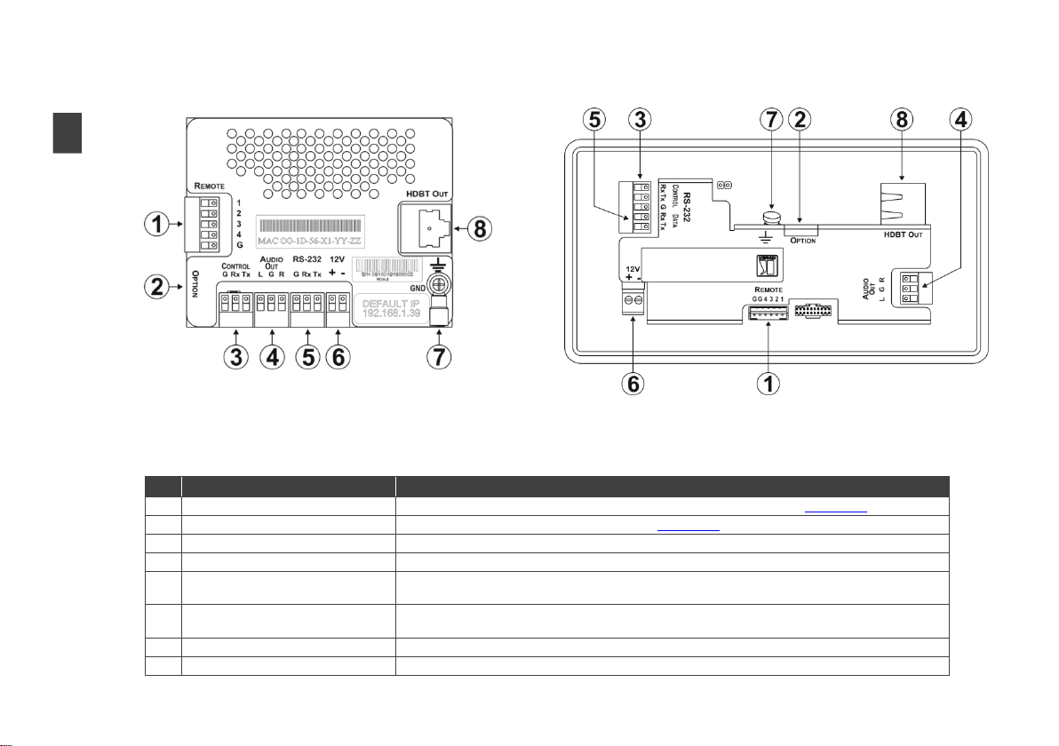
Figure 3: WP-20 Wall Plate Rear Panel
Figure 4: WP-20E Wall Plate Rear Panel
#
Feature
Function
1
REMOTE 5-pin Terminal Block
Connect to the remote, contact-closure switches for remote control, (see Section 5.1)
2
OPTION 4-way DIP-switch
Switches for setting the device behavior, (see Section 8.1)
3
CONTROL 3-pin Terminal Block
Connect to the serial controller to control the WP-20, (for example, a PC)
4
AUDIO OUT 3-pin Terminal Block
Connect to the unbalanced, stereo audio acceptor, (for example, amplified speakers)
5
RS-232 3-pin Terminal Block
Connect to the PC to transfer data via RS-232, (for example, a serial controller for a remote
device)
6
12V DC Connector
Connect to the supplied power adapter. Not needed on the WP-20 if there is a PoE provider over
HDBaseT
7
Earth Terminal
Connect to the common ground (optional)
8
HDBT OUT RJ-45 TP Connector
Connect to a compatible HDBT TP switcher or receiver (for example, the TP-588D/TP-580Rxr)
8
WP-20 – Defining the WP-20 Wall Plate
Figure 5: WP-20 Wall Plate Rear Panel
Page 14
WP-20 - Connecting the WP-20
9
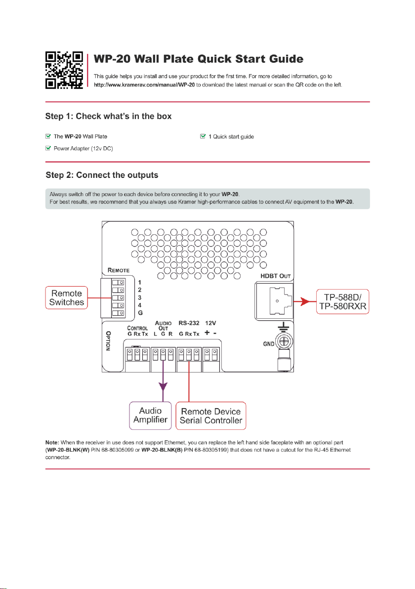
Always switch off the power to each device before connecting it to
your WP-20. After connecting your WP-20, connect its power and
then switch on the power to each device.
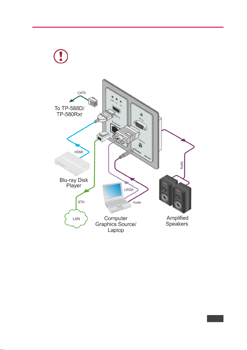
5 Connecting the WP-20
Figure 6: Connecting the WP-20 Wall Plate
Note: When the receiver in use does not support Ethernet, you can replace the
left hand side faceplate with an optional part (WP-20-BLNK(W) P/N 6880305099 or WP-20-BLNK(B) P/N 68-80305199) that does not have a cutout for
the RJ-45 Ethernet connector.
Page 15

10
WP-20 - Connecting the WP-20
To connect the WP-20, as illustrated in the example in Figure 6:
1. Connect an HDMI source, (for example, a Blu-ray disk player) to the
HDMI input.
1. Connect a PC graphics source, (for example, a laptop) to the PC In input.
2. Connect an unbalanced stereo audio source, (for example, the audio
output from the laptop) to the AUDIO IN 3.5mm mini jack.
3. Connect the Ethernet RJ-45 connector on the front panel to the LAN.
4. Connect the HDBT OUT RJ-45 connector on the rear panel of the
WP-20 to an HDBT-compatible receiver (for example, the TP-588D or
TP-580Rxr).
5. Connect the AUDIO OUT 3-pin terminal block on the rear panel of the
WP-20 to the unbalanced, stereo audio acceptor, (for example, a power
amplifier with speakers).
6. Connect the REMOTE, 5-way terminal block to momentary, contactclosure switches, (see Section 5.1).
7. If the device is not connected to a PoE provider, connect the power
adapter to the WP-20 and to the mains power, (not shown in Figure 6).
Note: All LED supplies include a current limiting resistor and are designed to
work with any standard LED.
Page 16
WP-20 - Connecting the WP-20
11
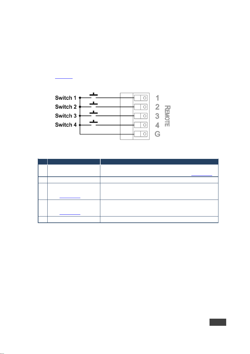
#
Feature
Function
1
Input selection/VGA
phase shift switch
Short press—Input toggle
Long press—Adjusts the VGA phase shift, (see Section 6.4)
2
Step-in switch
Activates the step-in function if relevant
3
Analog audio output
volume increase control,
(see Section 7.4)
Short press—Increases the volume one step
Long press—Increases the volume from 0% to 100% in 10
seconds
4
Analog audio output
volume decrease control,
(see Section 7.4)
Short press—Decreases the volume one step
Long press—Decreases the volume from 100% to 0% in 10
seconds
G
Ground
Connect to the common side of the switches
5.1 Connecting the Remote Control Switches
You can connect remote, momentary-contact contact-closure switches to the
terminal block on the rear panel of the WP-20 to control various functions of the
device.
Figure 7 illustrates the connections from the terminal block to the contact-closure
switches.
Figure 7: Remote Switches Terminal Block
Page 17

12
WP-20 - Principles of Operation
6 Principles of Operation
The WP-20 selects video and audio inputs based on the rules described below.
6.1 Input Selection
The video mode selection is set by the DIP-switches (see Section 8.1) to either
of the following modes:
Manual
Auto—Last connected or priority mode
In manual mode you select an input using either the remote input selection
switches, the Web-page interface, or P3000 commands, and switching occurs
whether or not there is a live signal present on the input.
In auto mode, the switching selection is performed based on either last
connected or priority input.
In last connected mode the WP-20 selects the input based on which input was
connected last. If the signal on this input is subsequently lost for any reason, the
input with a live signal and which was also the last connected is selected
automatically.
In priority mode, when the input sync signal is lost for any reason, the input with
a live signal and next in priority is selected automatically. This priority is
configurable; the default setting is HDMI > PC.
Note: In both last connected and priority modes, manually selecting an input
using the remote input selection switches overrides the last-connected automatic
selection.
Page 18

WP-20 - Principles of Operation
13
Selected
Video Input
HDMI Embedded
Audio Detected
Analog
Audio
Detected
DIP-switch
3
DIP-switch
4
Audio on HDBT
Output
VGA
N/A
Yes
N/A
N/A
Analog audio
VGA
N/A
No
N/A
N/A
No audio
HDMI
N/A
N/A
Manual
Embedded
Embedded audio
HDMI
N/A
N/A
Manual
Analog
Analog audio
HDMI
Yes
No
Auto
N/A
Embedded audio
HDMI
Yes
Yes
Auto
Embedded
Embedded audio
HDMI
Yes
Yes
Auto
Analog
Analog audio
HDMI
No
Yes
Auto
N/A
Analog audio
HDMI
No
No
Auto
N/A
No audio
6.2 Signal Loss and Unplugged Cable Timeouts
In both last connected and priority modes, when the input signal sync is lost (but
the cable is not removed) there is a default delay (ten seconds for video, not
applicable to the PC input, and five seconds for analog audio) before another
input is automatically selected. When an input cable is removed, there is a delay
before automatic switching takes place.
Both timeouts are configurable, (see Section 8.1).
Note: Analog audio is not output when there is no display connected. If a display
is connected, analog audio is output even in the absence of a video signal.
6.3 Audio Signal Control
The Option DIP-switches 3 and 4 (see Section 8.1) control the manner in which
audio is handled.
The following table describes which audio signal is embedded in the output.
When there is an audio signal but no video signal, the output is a black video
screen in conjunction with the analog audio signal.
Note: The default timeout for audio switching when the input signal is lost is five
seconds. This can be changed using either P3000 commands or the Web
pages.
Page 19

14
WP-20 - Principles of Operation
6.4 VGA Phase Shift
To minimize phase on the input VGA signal, the VGA sampling phase can be
shifted using a remote, contact-closure switch connected to pins 1 and G of the
Remote terminal block. Each long press steps the phase shift up one step
starting from 0 and going to 31. When the phase shift is set to 31, another long
press steps the shift to 0.
Page 20

WP-20 - Operating the WP-20
15
7 Operating the WP-20
Powering up the WP-20 recalls the last settings from the non-volatile memory,
(that is, the configuration of the device when it was powered down).
7.1 Selecting an Input Manually
Any of the following methods can be used to select an input:
Protocol 3000 command, (see Section 13.2)
Remote contact-closure switch, (see Section 5.1)
Web pages, (see Section 9)
7.2 Locking the EDID
To prevent the stored EDID (either default or read from a device) from being
overwritten, you can lock the current EDID by either sending a Protocol 3000
command or by using the Web pages.
Note: Do not power up the display before locking the EDID.
7.3 Resetting the WP-20
To perform a soft reset of the WP-20:
Briefly press the Reset button.
To reset the WP-20 to factory default parameters:
Press and hold the Reset button for five seconds.
The device resets
The device is reset to factory default parameters
Page 21

16
WP-20 - Operating the WP-20
Ramp
Volume Reading
Volume (dB)
1
100 0 1
99
–0.5 1 98
–1.0 1 97
–1.5 1 96
–2.0 1 …
(0.5 steps)
1
12
–44.0 1 11
–44.5 1 10
–45.0 1 9
–45.5 2 …
(2.0 steps)
2 8 –47.0 2 7
–49.0 2 6
–51.0
2 5 –53.0
2 4 –55.0 2 3
–57.0 2 2
–59.0 2 1
–61.0 2 0
–63.0
7.4 Analog Audio Output Volume Control
The analog audio output volume can be controlled using remote, contact-closure
switches connected to pins 3 and 4 of the Remote terminal block, (see
Section 5.1). For volume control using the Web pages, see Section 9.1 and for
using P3000 commands to control the volume see Section 13.2.
The up/down volume steps per press are detailed in the table below.
Page 22

WP-20 - Configuring the WP-20
17
#
Feature
Function
DIP-switch
1
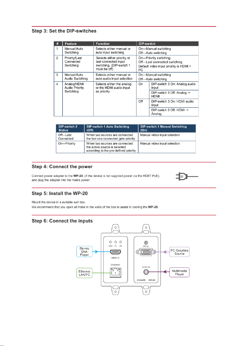
Manual/Auto
Switching
Selects either manual or
auto input switching
On—Manual switching
Off—Auto switching, (default)
2
Priority/Last
Connected
Switching
Selects either priority or
last connected input
switching, (DIP-switch 1
must be off)
On—Priority switching
Off—Last connected switching
Default video input priority is HDMI >
PC, (default)
3
Manual/Auto
Audio Switching
Selects either manual or
auto audio input selection
On—Manual switching
Off—Auto switching, (default)
4
Analog/HDMI
Audio Priority
Switching
Selects either the analog
or the HDMI audio input
as priority
On
DIP-switch 3 On: Analog audio
input
DIP-switch 3 Off: Analog
HDMI, (default)
Off
DIP-switch 3 On: HDMI audio
input
DIP-switch 3 Off: HDMI
Analog, (default)
DIP-switch 2
Status
DIP-switch 1 Auto Switching
(Off)
DIP-switch 1 Manual Switching
(On)
Off—Last
Connected
When two sources are connected
the last one connected gets priority
Manual video input selection
On—Priority
When two sources are connected
the active source is selected
according to the pre-defined priority
Manual video input selection
8 Configuring the WP-20
8.1 Setting the Configuration DIP-switch
The 4-way dip-switch provides the ability to configure a number of device
functions. A switch that is down is on; a switch that is up is off.
Figure 8: The Configuration DIP-switch
Note: After changing a dip-switch you must power cycle the device to implement
the change.
The following table describes the switching priorities defined by DIP-switches 1
and 2.
Page 23

18
WP-20 - Configuring the WP-20
Signal Loss, Power
Present
Signal and Power
Loss
Default Timeout
10 seconds
0 seconds
8.2 Video Switching Timeouts
When the WP-20 is configured for auto switching, the default timeouts before a
new input is automatically selected are shown in the table below. These can be
changed either by sending a Protocol 3000 command or by using the Web
pages.
Note: The minimum value of “Signal Loss, Power Present” is five seconds.
Page 24
WP-20 - Operating the WP-20 Remotely Using the Embedded Web Pages
19
9 Operating the WP-20 Remotely Using the
Embedded Web Pages
The WP-20 can be operated remotely using the embedded Web pages. The
Web pages are accessed using a Web browser and an Ethernet connection.
Before attempting to connect:
Ensure that your browser is supported (see Section 11)
Ensure that JavaScript is enabled
9.1 Browsing the WP-20 Web Pages
Note: In the event that a Web page does not update correctly, clear your Web
browser’s cache by pressing CTRL+F5.
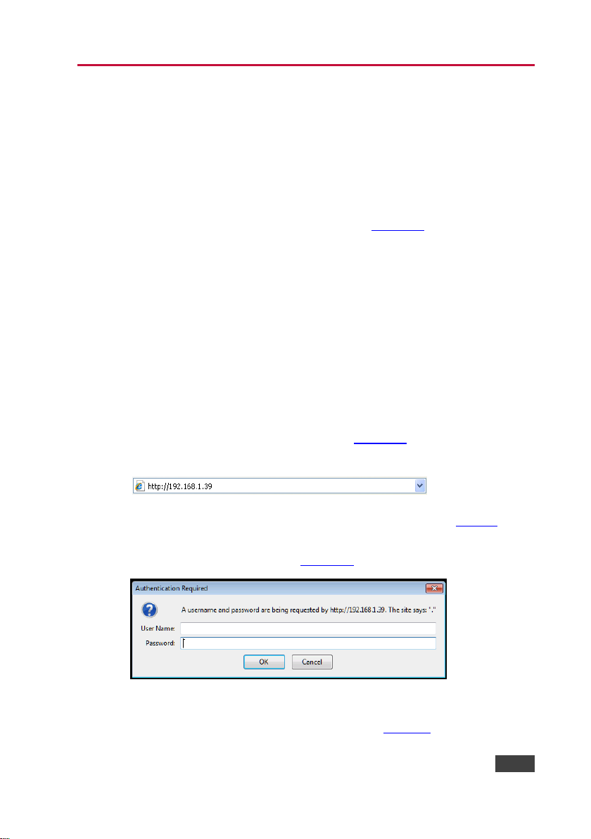
To browse the WP-20 Web pages:
1. Open your Internet browser.
2. Type the IP number of the device (see Section 11) in the Address bar of
your browser.
Note: If authentication is enabled, the following window appears (Figure 9) and
you must enter the valid username and password to access the Web pages. For
default authentication details, see Section 11.
Figure 9: Entering Logon Credentials
Following a successful logon, the screen shown in Figure 10 is displayed.
Page 25
20
WP-20 - Operating the WP-20 Remotely Using the Embedded Web Pages
#
Item
Description
1
Switching Details
Displays the current video and audio switching status
and the current audio volume
2
Left Hand Side Panel
Hide/Reveal Button
Click to reveal the left hand side page panel
Figure 10: The Default Page
Click the Reveal button to open the left hand side page panel.
The Switching page appears as shown in Figure 11.
Page 26

WP-20 - Operating the WP-20 Remotely Using the Embedded Web Pages
21
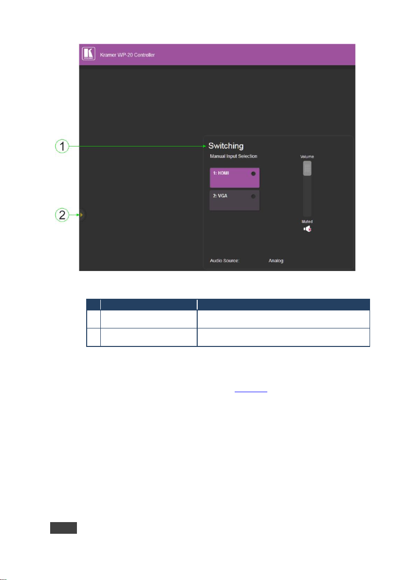
#
Item
Description
1
Page Selection Panel
Click one of the buttons to select a page
2
Video Input Switching
Selection
Click one of the buttons to select a video input
3
Page Selection Panel
Hide/Reveal Button
Click the arrow to open or close the page selection
panel
4
Audio Source Indication
Indicates the source of the audio that is currently on the
output
5
Upload/Save
Configuration Section
Click one of the buttons to save or retrieve a
configuration, (see Section 9.1.1)
6
Audio Volume Control
Use the slider to control the audio volume
7
Mute Button
Press to mute the volume. Press again to unmute the
volume
Figure 11: The Main Switching Page
The sections of the main switching page are described in the following table.
Note: When saving the configuration using Internet Explorer 11 press CTRL+S.
Page 27

22
WP-20 - Operating the WP-20 Remotely Using the Embedded Web Pages
There are six Web pages described in the following sections:
Switching (see Section 9.2)
Device Settings (see Section 9.3)
Video and Audio Settings (see Section 9.4)
Authentication (see Section 9.5)
EDID (see Section 9.6)
About Us (see Section 9.7)
9.1.1 The Upload/Save Configuration Facility
The Upload/Save Configuration facility (see item 4 in Figure 11) lets you retrieve
and save a configuration.
To upload a configuration:
1. Click the Upload button.
The File Upload browser window appears.
2. Browse to the required file and press Open.
The configuration is retrieved and the success message is displayed.
To save the current configuration:
1. Click the Save button.
The Save Configuration success message is displayed.
2. Do either of the following:
Click Download to either open the file or save it to the
required location
—OR—
Click OK to complete the procedure
Page 28

WP-20 - Operating the WP-20 Remotely Using the Embedded Web Pages
23
#
Item
Description
1
Live Signal Indicator
Indicates whether or not there is a live signal on either of
the inputs
2
HDMI Button
Click to select the HDMI input
3
VGA Button
Click to select the VGA input
4
Audio source Indicator
Indicates the source of the audio that is transmitted on the
output
5
Volume Slider
Click and slide up and down to increase or decrease the
audio output volume
6
Mute Button
Click to mute or unmute the output audio
9.2 The Switching Page
The Switching page lets you select a video input manually and adjust the audio
volume.
Figure 12: The Switching Page
9.3 The Device Settings Page
The Device Settings page lets you:
View some of the device characteristics, (for example, model and Web
version)
Edit IP settings, (for example, name and IP address)
Upgrade the firmware
Page 29

24
WP-20 - Operating the WP-20 Remotely Using the Embedded Web Pages
#
Item
Description
1
Information Section
Displays information regarding the device, (for
example, model, serial number, and MAC address)
2
DNS Name
The DNS name of the device. To set a new name,
enter the new alphanumeric name and click Set. (For
restrictions regarding the name, see Section 11.2)
3
DHCP Buttons
Click ON to turn DHCP on; click OFF to turn DHCP off
4
IP Address
The IP address of the device. To set a new IP address,
enter the new IP address and click Set
5
Mask
The network mask of the device. To set a new mask,
enter the new mask address and click Set
6
Gateway
The network gateway for the device. To set a new
network gateway, enter the new gateway address and
click Set
Reset the device to factory default settings
Note: After making any change to the parameters on the Device Settings page,
you must power cycle the device to activate the changes.
Figure 13: The Device Settings Page
Page 30

WP-20 - Operating the WP-20 Remotely Using the Embedded Web Pages
25
#
Item
Description
7
TCP Port
The TCP port number of the device. To set a new TCP
port number, enter the new port number or use the spin
controls and click Set
8
UDP Port
The UDP port number of the device. To set a new UDP
port number, enter the new port number or use the spin
controls and click Set
9
Firmware
upgrade
Section
BROWSE
button
Click to open a window to browse to the new firmware
file
10
START
UPGRADE
button
Click to start the upgrade process following the
selection of the new firmware file
11
Factory Reset Button
Click to reset the device to factory default parameters.
After the success message is displayed, power cycle
the device
12
Set Button
Click to store a changed parameter.
Note: If you do not click the Set button, the new
parameter is not stored
Do not interrupt the process or the WP-20 may be damaged.
!
To upgrade the firmware:
1. Click the Browse button.
The Windows Browser opens.
2. Browse to the required file.
3. Select the required file and click Open.
The firmware file name is displayed in the Firmware Upgrade page.
4. Click Start Upgrade.
The firmware file is loaded and a progress bar is displayed.
5. When the process is complete reboot the device.
The firmware is upgraded.
To reset the WP-20 to factory default parameters:
1. Click the Factory reset button.
The confirmation message is displayed.
2. Click OK to continue or Cancel to exit the procedure.
Page 31

26
WP-20 - Operating the WP-20 Remotely Using the Embedded Web Pages
#
Item
Description
1
Video
Section
Video selection
mode Indicator
Indicates the current video selection mode;
manual, auto, or auto last connected
2
Video auto
switching priority
Buttons
Click either the HDMI or VGA buttons to select
the priority selection when in auto mode
3. Click OK.
The progress message is displayed.
On completion, the success message is displayed.
4. Click OK.
9.4 The Video and Audio Settings Page
The Video and Audio Settings page lets you modify the video, audio and timeout
parameters.
Figure 14: The Video and Audio Settings Page
Page 32

WP-20 - Operating the WP-20 Remotely Using the Embedded Web Pages
27
#
Item
Description
3
Audio
Section
Audio selection
mode Indicator
Indicates the current audio selection; manual,
auto, or auto last connected
4
Current selection
Audio Indicator
Indicates the current audio selection
5
HDCP Support (on
HDMI input)
Buttons
Not supported—HDCP encrypted content is not
passed.
Follow output—HDCP support is dictated by the
display
6
Timeout
Section
Delay switching
upon signal loss for
(leave 5V on) Box
Sets the delay for video (0 to 900 seconds) and
audio (0 to 900 seconds) before switching (in
auto mode) because of a signal loss on the
currently selected input
7
Delay switching
input upon cable
unplug for Box
Sets the delay for video (0 to 900 seconds) and
audio (0 to 900 seconds) before switching (in
auto mode) because the currently selected input
cable is unplugged
8
Delay power off 5V
upon signal loss for
Box
Sets the delay for turning off the 5V output (0 to
60,000 seconds) because of a signal loss on
the currently selected input
Note: When enabling or disabling HDCP, disconnect and reconnect the HDMI
cable between the source and the WP-20.
9.5 The Authentication Page
The Authentication page lets you assign or change logon authentication details.
Figure 15: The Authentication Page
Page 33

28
WP-20 - Operating the WP-20 Remotely Using the Embedded Web Pages
#
Item
Description
1
Activate Security Button
Click to enable/disable security settings. When
enabled, the valid username and password must
be provided to allow Web page access
2
Change
Password:
Section
Current
Password box
Enter the current password
3
New Password
box
Enter the new password, (up to 15 printable ASCII
characters)
4
Retype New
Password box
Retype the new password
5
CHANGE
button
Click CHANGE to save the new authentication
details
Note: If the Authentication page is left open for more than five minutes additional
windows may open. After entering your logon credentials, close the other
windows.
9.6 The EDID Page
The EDID page lets you copy EDID data to either or both of the inputs from any
of the following sources:
Output
Input
Default EDID
EDID data file
From this page you can also lock the EDID on each input independently.
Note: Do not power up the display before locking the EDID.
Page 34

WP-20 - Operating the WP-20 Remotely Using the Embedded Web Pages
29
#
Item
Description
1
Read
from
Section
DEFAULT EDID
button
Click to read the default EDID
2
Output 1 button
Click to read the EDID from output 1
3
Input 1 button
Click to read the EDID from input 1 (HDMI)
4
Input 2 button
Click to read the EDID from input 2 (VGA)
5
BROWSE button
Click to open the file browser to select an EDID
file on your computer
6
Short Summary Information
Section
Displays the current election of EDID source,
destination, video resolution, audio availability,
and status
7
Copy to
Section
Inputs selection box
Check to select both inputs
8
Lock button
Locks the EDID on the currently selected input
9
Input 1 button
Click to select input 1 as the destination (HDMI)
10
Input 2 button
Click to select input 2 as the destination (VGA)
11
COPY Button
Click to copy the EDID from the selected source
to the selected destination
12
Refresh Button
Click to refresh the display
Figure 16: The EDID Page
Note: The display is not updated automatically when the status of an EDID
changes on the device caused by outputs being exchanged. Click Refresh to
update the display, (see item 12 in the following table).
Page 35

30
WP-20 - Operating the WP-20 Remotely Using the Embedded Web Pages
To copy EDID data from a source to one or both inputs:
1. Click one of the source buttons from which to read the EDID (default,
output, input, or EDID file).
The button changes color and the EDID summary information reflects the
selection and EDID data.
2. Click one of the destination inputs, or select both inputs by checking the
Inputs check-box.
All selected input buttons change color and the EDID summary
information reflects the selection and EDID data.
3. Click the Copy button.
The EDID data is copied to the selected input(s) and the “EDID was
copied” success message is displayed.
4. Click OK.
9.7 The About Us Page
The WP-20 About Us page displays the Web page version and Kramer
Electronics Ltd company details.
Figure 17: The About Us Page
Page 36

WP-20 - Wiring the Twisted Pair RJ-45 Connectors
31
EIA /TIA 568B
Figure 18: TP Pinout Wiring
PIN
Wire Color
1
Orange / White
2
Orange
3
Green / White
4
Blue
5
Blue / White
6
Green
7
Brown / White
8
Brown
Pair 1
4 and 5
Pair 2
1 and 2
Pair 3
3 and 6
10 Wiring the Twisted Pair RJ-45 Connectors
When using STP cable, connect/solder the cable shield to the RJ-45 connector
shield. Figure 18 defines the TP pinout using a straight pin-to-pin cable with
RJ-45 connectors.
Page 37

32
WP-20 - Technical Specifications
INPUTS:
Video:
1 HDMI on an HDMI connector
1 VGA on a 15-pin HD (F) connector
Audio:
1 Unbalanced stereo audio on a 3.5mm mini jack
OUTPUTS:
1 HDBaseT on an RJ-45 connector
1 Unbalanced stereo audio on a 3.5mm mini jack
PORTS:
1 RS-232 3-pin terminal block
1 Ethernet on an RJ-45 connector
CONTROLS:
Remote switches for input switching and volume control,
reset switch
STANDARDS:
HDMI with Deep Color, x.v.Color™ and 3D
HDCP—works with sources that support HDCP repeater
mode
HDBT certified
MAXIMUM ANALOG
AUDIO LEVEL:
3.1V p-p
THD:
0.013%
SNR:
–70dB
SUPPORTED WEB
BROWSERS:
Windows 7 and higher:
Internet Explorer (32/64 bit) version 11
Firefox version 30
Chrome version 35
MAC:
Chrome version 35
Firefox version 27
Safari version 7
MAXIMUM
TRANSMISSION
DISTANCE:
180m (590ft) up to 1080p @60Hz @24bpp in extended
mode
130m (430ft) up to 1080p @60Hz @36bpp in normal mode
POWER
CONSUMPTION:
12V DC, 850mA
OPERATING
TEMPERATURE:
0° to +40°C (32° to 104°F)
STORAGE
TEMPERATURE:
–40° to +70°C (–40° to 158°F)
HUMIDITY:
10% to 90%, RHL non-condensing
COOLING:
Convection
ENCLOSURE TYPE:
Aluminium
DIMENSIONS:
2 Gang USA 11.6 cm x 5.1cm x 11.4cm (4.57” x 2.01” x
4.49”) W, D, H
2 Gang EU 15.1cm x 4.7cm x 8.6cm (5.94” x 1.85” x 3.39”)
W, D, H
WEIGHT:
0.23kg (0.51lbs) approx.
SHIPPING WEIGHT:
0.51kg (1.12lbs) approx.
ENVIRONMENTAL
REGULATORY
COMPLIANCE:
Complies with appropriate requirements of RoHs and WEEE
VIBRATION:
ISTA 1A in carton (International Safe Transit Association)
11 Technical Specifications
Page 38

WP-20 - Technical Specifications
33
COMPLIANCE
STANDARDS:
CE
INCLUDED
ACCESSORIES:
Power adapter
OPTIONS:
Faceplates:
WP-20-BLNK(W) P/N 68-80305099
WP-20-BLNK(B) P/N 68-80305199
WARRANTY:
7 years parts and labor
Parameter
Values
Default
Device
Name
Any alphanumeric string up to 14 chars (can
include hyphen, but not at the beginning or
end)
KRAMER_
DHCP
ON/OFF
OFF
IP Address
Any valid IP address
192.168.1.39
Mask
Any valid network mask
255.255.0.0
Gateway
Any valid gateway address
192.168.0.1
TCP Port
0 to 65535
5000
UDP Port
0 to 65535
50000
Parameter
Values
Name
Admin
Password
Admin
Resolution
Refresh Rate (Hz)
640x480p
85Hz; 75Hz; 72Hz; 60Hz; 59.95Hz
720x480p
60Hz
720x480i
30Hz
720x576p
50Hz
800x600p
85Hz; 75Hz; 72Hz; 60Hz
848x480p
60Hz
852x480p
60Hz
1024x768p
85Hz; 75Hz; 70Hz; 60Hz
1152x864p
75Hz
1280x768p
60Hz
11.1 Default IP Parameters
11.2 Default Logon Credentials
11.3 Supported Resolutions
11.3.1 HDMI
Page 39

34
WP-20 - Technical Specifications
Resolution
Refresh Rate (Hz)
1280x800p
60Hz
1280x960
60Hz
1280x1024p
75Hz; 60Hz
1360x768p
60Hz
1366x768
60Hz; 50Hz
1400x1050p
60Hz
1440x900p
60Hz
1600x900p
60Hz
1600x1200p
60Hz
1680x1050p
60Hz
1920x1080p
50Hz; 60Hz; 30Hz; 24Hz;
1920x1080i
50Hz; 60Hz;
3840x2160
30Hz
4096x2160
30Hz
Resolution
Refresh Rate
640x480p
60Hz
720x480p
60Hz
800x600p
60Hz
848x480p
60Hz
1024x768p
60Hz
1152x864
75Hz
1280x720p
60Hz; 50Hz
1280x768
60Hz
1280x800
60Hz
1280x960p
60Hz
1280x1024p
60Hz
1360x768
60Hz;
1366x768
60Hz; 50Hz
1400x1050
60Hz
1440x900
60Hz
1920x1080p
60Hz
1920x1200
60Hz; 50Hz
11.3.2 VGA
Page 40

WP-20 - Default EDID
35
12 Default EDID
Each input on the WP-20 is loaded with a factory default EDID.
12.1 HDMI
Monitor
Model name............... WP-20
Manufacturer............. KMR
Plug and Play ID......... KMR1200
Serial number............ n/a
Manufacture date......... 2015, ISO week 255
Filter driver............ None
-------------------------
EDID revision............ 1.3
Input signal type........ Digital
Color bit depth.......... Undefined
Color encoding formats... RGB color
Screen size.............. 520 x 320 mm (24.0 in)
Power management......... Standby, Suspend, Active off/sleep
Extension blocs.......... 1 (CEA-EXT)
-------------------------
DDC/CI................... n/a
Color characteristics
Default color space...... Non-sRGB
Display gamma............ 2.20
Red chromaticity......... Rx 0.674 - Ry 0.319
Green chromaticity....... Gx 0.188 - Gy 0.706
Blue chromaticity........ Bx 0.148 - By 0.064
White point (default).... Wx 0.313 - Wy 0.329
Additional descriptors... None
Timing characteristics
Horizontal scan range.... 30-83kHz
Vertical scan range...... 56-76Hz
Video bandwidth.......... 170MHz
CVT standard............. Not supported
GTF standard............. Not supported
Additional descriptors... None
Preferred timing......... Yes
Native/preferred timing.. 1280x720p at 60Hz (16:10)
Modeline............... "1280x720" 74.250 1280 1390 1430 1650 720 725 730 750 +hsync +vsync
Standard timings supported
720 x 400p at 70Hz - IBM VGA
720 x 400p at 88Hz - IBM XGA2
640 x 480p at 60Hz - IBM VGA
640 x 480p at 67Hz - Apple Mac II
640 x 480p at 72Hz - VESA
640 x 480p at 75Hz - VESA
800 x 600p at 56Hz - VESA
800 x 600p at 60Hz - VESA
800 x 600p at 72Hz - VESA
800 x 600p at 75Hz - VESA
832 x 624p at 75Hz - Apple Mac II
1024 x 768i at 87Hz - IBM
1024 x 768p at 60Hz - VESA
1024 x 768p at 70Hz - VESA
1024 x 768p at 75Hz - VESA
1280 x 1024p at 75Hz - VESA
1152 x 870p at 75Hz - Apple Mac II
1280 x 1024p at 75Hz - VESA STD
1280 x 1024p at 85Hz - VESA STD
1600 x 1200p at 60Hz - VESA STD
1024 x 768p at 85Hz - VESA STD
Page 41

36
WP-20 - Default EDID
800 x 600p at 85Hz - VESA STD
640 x 480p at 85Hz - VESA STD
1152 x 864p at 70Hz - VESA STD
1280 x 960p at 60Hz - VESA STD
EIA/CEA-861 Information
Revision number.......... 3
IT underscan............. Supported
Basic audio.............. Supported
YCbCr 4:4:4.............. Supported
YCbCr 4:2:2.............. Supported
Native formats........... 1
Detailed timing #1....... 1920x1080p at 60Hz (16:10)
Modeline............... "1920x1080" 148.500 1920 2008 2052 2200 1080 1084 1089 1125 +hsync +vsync
Detailed timing #2....... 1920x1080i at 60Hz (16:10)
Modeline............... "1920x1080" 74.250 1920 2008 2052 2200 1080 1084 1094 1124 interlace +hsync
+vsync
Detailed timing #3....... 1280x720p at 60Hz (16:10)
Modeline............... "1280x720" 74.250 1280 1390 1430 1650 720 725 730 750 +hsync +vsync
Detailed timing #4....... 720x480p at 60Hz (16:10)
Modeline............... "720x480" 27.000 720 736 798 858 480 489 495 525 -hsync -vsync
CE audio data (formats supported)
LPCM 2-channel, 16/20/24 bit depths at 32/44/48 kHz
CE video identifiers (VICs) - timing/formats supported
1920 x 1080p at 60Hz - HDTV (16:9, 1:1)
1920 x 1080i at 60Hz - HDTV (16:9, 1:1)
1280 x 720p at 60Hz - HDTV (16:9, 1:1) [Native]
720 x 480p at 60Hz - EDTV (16:9, 32:27)
720 x 480p at 60Hz - EDTV (4:3, 8:9)
720 x 480i at 60Hz - Doublescan (16:9, 32:27)
720 x 576i at 50Hz - Doublescan (16:9, 64:45)
640 x 480p at 60Hz - Default (4:3, 1:1)
NB: NTSC refresh rate = (Hz*1000)/1001
CE vendor specific data (VSDB)
IEEE registration number. 0x000C03
CEC physical address..... 1.0.0.0
Maximum TMDS clock....... 165MHz
CE speaker allocation data
Channel configuration.... 2.0
Front left/right......... Yes
Front LFE................ No
Front center............. No
Rear left/right.......... No
Rear center.............. No
Front left/right center.. No
Rear left/right center... No
Rear LFE................. No
Report information
Date generated........... 31/12/2014
Software revision........ 2.60.0.972
Data source.............. File
Operating system......... 6.1.7601.2.Service Pack 1
Raw data
00,FF,FF,FF,FF,FF,FF,00,2D,B2,00,12,01,01,01,01,FF,18,01,04,80,34,20,78,EA,B3,25,AC,51,30,B4,26,
10,50,54,FF,FF,80,81,8F,81,99,A9,40,61,59,45,59,31,59,71,4A,81,40,01,1D,00,72,51,D0,1E,20,6E,28,
55,00,07,44,21,00,00,1E,00,00,00,FF,00,35,30,35,2D,38,30,33,30,35,30,31,30,30,00,00,00,FC,00,57,
50,2D,35,56,48,32,00,00,00,00,00,00,00,00,00,FD,00,38,4C,1E,53,11,00,0A,20,20,20,20,20,20,01,AF,
02,03,1B,F1,23,09,07,07,48,10,05,84,03,02,07,16,01,65,03,0C,00,10,00,83,01,00,00,02,3A,80,18,71,
38,2D,40,58,2C,45,00,07,44,21,00,00,1E,01,1D,80,18,71,1C,16,20,58,2C,25,00,07,44,21,00,00,9E,01,
1D,00,72,51,D0,1E,20,6E,28,55,00,07,44,21,00,00,1E,8C,0A,D0,8A,20,E0,2D,10,10,3E,96,00,07,44,21,
00,00,18,00,00,00,00,00,00,00,00,00,00,00,00,00,00,00,00,00,00,00,00,00,00,00,00,00,00,00,00,47
Page 42

WP-20 - Default EDID
37
12.2 PC-UXGA
Monitor
Model name............... WP-20
Manufacturer............. KMR
Plug and Play ID......... KMR1200
Serial number............ n/a
Manufacture date......... 2015, ISO week 255
Filter driver............ None
-------------------------
EDID revision............ 1.5
Input signal type........ Analog 0.700,0.000 (0.7V p-p)
Sync input support....... Separate, Composite, Sync-on-green
Display type............. RGB color
Screen size.............. 520 x 320 mm (24.0 in)
Power management......... Standby, Suspend, Active off/sleep
Extension blocs.......... None
-------------------------
DDC/CI................... n/a
Color characteristics
Default color space...... sRGB
Display gamma............ 2.20
Red chromaticity......... Rx 0.674 - Ry 0.319
Green chromaticity....... Gx 0.188 - Gy 0.706
Blue chromaticity........ Bx 0.148 - By 0.064
White point (default).... Wx 0.313 - Wy 0.329
Additional descriptors... None
Timing characteristics
Horizontal scan range.... 30-83kHz
Vertical scan range...... 56-76Hz
Video bandwidth.......... 170MHz
CVT standard............. Not supported
GTF standard............. Not supported
Additional descriptors... None
Preferred timing......... Yes
Native/preferred timing.. 1280x720p at 60Hz (16:10)
Modeline............... "1280x720" 74.250 1280 1390 1430 1650 720 725 730 750 +hsync +vsync
Standard timings supported
720 x 400p at 70Hz - IBM VGA
720 x 400p at 88Hz - IBM XGA2
640 x 480p at 60Hz - IBM VGA
640 x 480p at 67Hz - Apple Mac II
640 x 480p at 72Hz - VESA
640 x 480p at 75Hz - VESA
800 x 600p at 56Hz - VESA
800 x 600p at 60Hz - VESA
800 x 600p at 72Hz - VESA
800 x 600p at 75Hz - VESA
832 x 624p at 75Hz - Apple Mac II
1024 x 768i at 87Hz - IBM
1024 x 768p at 60Hz - VESA
1024 x 768p at 70Hz - VESA
1024 x 768p at 75Hz - VESA
1280 x 1024p at 75Hz - VESA
1152 x 870p at 75Hz - Apple Mac II
1280 x 1024p at 75Hz - VESA STD
1280 x 1024p at 85Hz - VESA STD
1600 x 1200p at 60Hz - VESA STD
1024 x 768p at 85Hz - VESA STD
800 x 600p at 85Hz - VESA STD
640 x 480p at 85Hz - VESA STD
1152 x 864p at 70Hz - VESA STD
1280 x 960p at 60Hz - VESA STD
Raw data
00,FF,FF,FF,FF,FF,FF,00,2D,B2,00,12,01,01,01,01,FF,18,01,04,6E,34,20,78,EE,B3,25,AC,51,30,B4,26,
10,50,54,FF,FF,80,81,8F,81,99,A9,40,61,59,45,59,31,59,71,4A,81,40,01,1D,00,72,51,D0,1E,20,6E,28,
55,00,07,44,21,00,00,1E,00,00,00,FF,00,35,30,35,2D,38,30,33,30,35,30,31,30,30,00,00,00,FC,00,57,
50,2D,35,56,48,32,00,00,00,00,00,00,00,00,00,FD,00,38,4C,1E,53,11,00,0A,20,20,20,20,20,20,00,BE
Page 43

38
WP-20 - Protocol 3000
Start
Address (optional)
Body
Delimiter
#
Destination_id@
Message
CR
Start
Body
Delimiter
#
Command SP Parameter_1,Parameter_2,…
CR
Start
Address
Body
Delimiter
#
Destination_id@
Command_1 Parameter1_1,Parameter1_2,…|
Command_2 Parameter2_1,Parameter2_2,…|
Command_3
Parameter3_1,Parameter3_2,…|…
CR
Start
Address (optional)
Body
delimiter
~
Sender_id@
Message
CR LF
Start
Address (optional)
Body
Delimiter
~
Sender_id@
Command SP [Param1 ,Param2 …] result
CR LF
13 Protocol 3000
The WP-20 can be operated using serial commands from a PC, remote
controller or touch screen using the Kramer Protocol 3000.
This section describes:
Kramer Protocol 3000 syntax (see Section 13.1)
Kramer Protocol 3000 commands (see Section 13.2)
13.1 Kramer Protocol 3000 Syntax
13.1.1 Host Message Format
13.1.2 Simple Command
Command string with only one command without addressing:
13.1.3 Command String
Formal syntax with commands concatenation and addressing:
13.1.4 Device Message Format
13.1.5 Device Long Response
Echoing command:
CR = Carriage return (ASCII 13 = 0x0D)
Page 44

WP-20 - Protocol 3000
39
LF = Line feed (ASCII 10 = 0x0A)
SP = Space (ASCII 32 = 0x20)
13.1.6 Command Terms
Command
A sequence of ASCII letters ('A'-'Z', 'a'-'z' and '-').
Command and parameters must be separated by at least one space.
Parameters
A sequence of alphanumeric ASCII characters ('0'-'9','A'-'Z','a'-'z' and some
special characters for specific commands). Parameters are separated by
commas.
Message string
Every command entered as part of a message string begins with a message
starting character and ends with a message closing character.
Note: A string can contain more than one command. Commands are separated
by a pipe ( '|' ) character.
Message starting character
'#' – For host command/query
'~' – For device response
Device address (Optional, for K-NET)
K-NET Device ID followed by '@'
Query sign
'?' follows some commands to define a query request.
Message closing character
CR – For host messages; carriage return (ASCII 13)
CRLF – For device messages; carriage return (ASCII 13) + line-feed (ASCII 10)
Command chain separator character
When a message string contains more than one command, a pipe ( '|' )
character separates each command.
Page 45

40
WP-20 - Protocol 3000
Spaces between parameters or command terms are ignored.
13.1.7 Entering Commands
You can directly enter all commands using a terminal with ASCII
communications software, such as HyperTerminal, Hercules, etc. Connect the
terminal to the serial or Ethernet port on the Kramer device. To enter CR press
the Enter key.
( LF is also sent but is ignored by command parser).
For commands sent from some non-Kramer controllers, (for example, Crestron)
some characters require special coding (such as, /X##). Refer to the controller
manual.
13.1.8 Command Forms
Some commands have short name syntax in addition to long name syntax to
allow faster typing. The response is always in long syntax.
13.1.9 Chaining Commands
Multiple commands can be chained in the same string. Each command is
delimited by a pipe character (“|”). When chaining commands, enter the
message starting character and the message closing character only once, at
the beginning of the string and at the end.
Commands in the string do not execute until the closing character is entered. A
separate response is sent for every command in the chain.
13.1.10 Maximum String Length
64 characters
Page 46

WP-20 - Protocol 3000
41
Command
Description
#
Protocol handshaking
BUILD-DATE?
Get device build date
FACTORY
Reset to factory default configuration
HELP
Get command list
MODEL?
Get device model
PROT-VER?
Get device protocol version
RESET
Reset device
SN?
Get device serial number
VERSION?
Get device firmware version
AV-SW-MODE
Set/get auto switch mode
AV-SW-TIMEOUT
Set/get auto switching timeout
DISPLAY?
Get output HPD status
FPGA-VER?
Get current FPGA version
HDCP-MOD
Set/get HDCP mode
HDCP-STAT?
Get HDCP signal status
LDFW
Load new firmware file
NAME
Set/get machine (DNS) name
NAME-RST
Reset machine name to factory default (DNS)
PRIORITY
Set/get priority for all channels
SIGNAL?
Get input signal lock status
13.2 Kramer Protocol 3000 Commands
The following table lists the Protocol 3000 commands that the WP-20 supports.
For a full description of the commands, see the Kramer Protocol 3000 document
available from http://www.kramerelectronics.com.
Note: The WP-20 can only receive commands from a device, (for example, an
HDBT transmitter) via the HDBaseT link, and only at 9600bps.
13.2.1 System Commands
Page 47

42
WP-20 - Protocol 3000
Command - #
Command Type - System-mandatory
Command Name
Permission
Transparency
Set: # End User
Public
Get: - -
-
Description
Syntax
Set:
Protocol handshaking
#␍
Get: - -
Response
~nn@␠OK␍␊
Parameters
Response Triggers
Notes
Validates the Protocol 3000 connection and gets the machine number
Step-in master products use this command to identify the availability of a device
Command - BUILD-DATE
Command Type - System-mandatory
Command Name
Permission
Transparency
Set: - - - Get:
BUILD-DATE?
End User
Public
Description
Syntax
Set:
Get device build date
#BUILD-DATE␍
Get: - -
Response
~nn@BUILD-DATE␠ date␠time␍␊
Parameters
date - Format: YYYY/MM/DD where YYYY = Year, MM = Month, DD = Day
time - Format: hh:mm:ss where hh = hours, mm = minutes, ss = seconds
Response Triggers
Notes
Page 48

WP-20 - Protocol 3000
43
Command - HELP
Command Type - System-mandatory
Command Name
Permission
Transparency
Set: - - - Get:
HELP
End User
Public
Description
Syntax
Set: - -
Get:
Get command list or help for specific
command
2 options:
1. #HELP␍
2. #HELP␠ command_name␍
Response
1. Multi-line: ~nn@Device available protocol 3000 commands: ␍␊ command,␠command…␍␊
To get help for command use: HELP (COMMAND_NAME)␍␊
2. Multi-line: ~nn@HELP␠ command: ␍␊description␍␊ USAGE:usage ␍␊
Parameters
Response Triggers
Notes
Command - MODEL?
Command Type - System-mandatory
Command Name
Permission
Transparency
Set: - -
-
Get:
MODEL?
End User
Public
Description
Syntax
Set: - -
Get:
Get device model
#MODEL?␍
Response
~nn@MODEL␠ model_name␍␊
Parameters
model_name - String of up to 19 printable ASCII chars
Response Triggers
Notes
This command identifies equipment connected to Step-in master products and notifies of identity changes
to the connected equipment. The Matrix saves this data in memory to answer REMOTE-INFO requests
Page 49

44
WP-20 - Protocol 3000
Command - PROT-VER?
Command Type - System-mandatory
Command Name
Permission
Transparency
Set: - - - Get:
PROT-VER?
End User
Public
Description
Syntax
Set: - -
Get:
Get device protocol version
#PROT-VER?␍
Response
~nn@PROT-VER␠ 3000:version␍␊
Parameters
Version - XX.XX where X is a decimal digit
Response Triggers
Notes
Command - RESET
Command Type - System-mandatory
Command Name
Permission
Transparency
Set:
RESET
Administrator
Public
Get: - -
-
Description
Syntax
Set:
Reset device
#RESET␍
Get: - -
Response
~nn@RESET␠ OK␍␊
Parameters
Response Triggers
Notes
To avoid locking the port due to a USB bug in Windows, disconnect USB connections immediately after
running this command. If the port was locked, disconnect and reconnect the cable to reopen the port.
Page 50

WP-20 - Protocol 3000
45
Command - SN?
Command Type - System-mandatory
Command Name
Permission
Transparency
Set: - - - Get:
SN?
End User
Public
Description
Syntax
Set: - -
Get:
Get device serial number
#SN?␍
Response
~nn@SN␠serial_number␍␊
Parameters
serial_number - 11 decimal digits, factory assigned
Response Triggers
Notes
For new products with 14 digit serial numbers, use only the last 11 digits
Command - VERSION?
Command Type - System-mandatory
Command Name
Permission
Transparency
Set: - - - Get:
VERSION?
End User
Public
Description
Syntax
Set: - -
Get:
Get firmware version number
#VERSION?␍
Response
~nn@VERSION␠ firmware_version␍␊
Parameters
firmware_version - XX.XX.XXXX where the digit groups are: major.minor.build version
Response Triggers
Notes
Page 51

46
WP-20 - Protocol 3000
Command - AV-SW-MODE
Command Type - System
Command Name
Permission
Transparency
Set:
AV-SW-MODE
End user
Public
Get:
AV-SW-MODE?
End user
Public
Description
Syntax
Set:
Set input auto switch mode (per output)
# AV-SW-MODE␠ layer,output_id,mode␍
Get:
Get input auto switch mode (per output)
# AV-SW-MODE?␠ layer,output_id␍
Response
~ nn@AV-SW-MODE␠ layer,output_id,mode␍␊
Parameters
layer (see Section 13.2.10)
output_id - 1….num of system outputs
mode - 0 - manual
1 - priority switch
2 - last connected switch
Response Triggers
Notes
Command - AV-SW-TIMEOUT
Command Type - System
Command Name
Permission
Transparency
Set:
AV-SW-TIMEOUT
End User
Public
Get:
AV-SW-TIMEOUT?
End User
Public
Description
Syntax
Set:
Set auto switching timeout
#AV-SW-TIMEOUT␠ action,time_out ␍
Get:
Get auto switching timeout
#AV-SW-TIMEOUT?␠ action ␍
Response
~ nn@AV-SW-TIMEOUT␠ action,time_out ␍
Parameters
action (see Section 13.2.11)
timeout - timeout in seconds
Response Triggers
Notes
Page 52

WP-20 - Protocol 3000
47
Command - DISPLAY?
Command Type - System
Command Name
Permission
Transparency
Set: - - - Get
DISPLAY?
End User
Public
Description
Syntax
Set: - -
Get:
Get output HPD status
#DISPLAY?␠ out_id␍
Response
~ nn@DISPLAY␠out_id,status ␍␊
Parameters
out_id - output number
status - HPD status according to signal validation
Response Triggers
After execution, response is sent to the com port from which the Get was received
Response is sent after every change in output HPD status ON to OFF
Response is sent after every change in output HPD status OFF to ON and ALL parameters (new EDID,
etc.) are stable and valid
Notes
Command - FPGA-VER?
Command Type - System
Command Name
Permission
Transparency
Set: - - - Get:
FPGA-VER?
End User
Public
Description
Syntax
Set: - -
Get:
Get current FPGA version
#FPGA-VER?␠id␍
Response
~nn@FPGA-VER␠ id, expected_ver, actual_ver␍␊
Parameters
id - FPGA id
expected_ver - expected FPGA version for current firmware
actual_ver - actual FPGA version
Response Triggers
Notes
Page 53

48
WP-20 - Protocol 3000
Command - HDCP-MOD
Command Type - System
Command Name
Permission
Transparency
Set:
HDCP-MOD
Administrator
Public
Get:
HDCP-MOD?
End User
Public
Description
Syntax
Set:
Set HDCP mode
#HDCP-MOD␠ inp_id,mode␍
Get:
Get HDCP mode
#HDCP-MOD?␠ stage_id␍
Response
Set / Get: ~ nn @HDCP-MOD␠ stage_id,mode␍␊
Parameters
inp_id - input number (1.. max number of inputs)
mode - HDCP mode
Response Triggers
Response is sent to the com port from which the Set (before execution) / Get command was received
Response is sent to all com ports after execution if HDCP-MOD was set by any other external control
device (button press, device menu and similar) or HDCP mode changed
Notes
Set HDCP working mode on the device input:
HDCP supported - HDCP_ON [default]
HDCP not supported - HDCP OFF
HDCP support changes following detected sink - MIRROR OUTPUT
Page 54

WP-20 - Protocol 3000
49
Command - HDCP-STAT
Command Type - System
Command Name
Permission
Transparency
Set: - - - Get:
HDCP-STAT?
End User
Public
Description
Syntax
Set:
None
-
Get:
Get HDCP signal status
#HDCP-STAT?␠ stage,stage_id␍
Response
Set / Get: ~ nn@HDCP-STAT␠ stage,stage_id,mode␍␊
Parameters
stage – input/output
stage_id - number of chosen stage (1.. max number of inputs/outputs)
actual_status - signal encryption status - valid values ON/OFF
Response Triggers
Response is sent to the com port from which the Set (before execution) / Get command was received
Response is sent to all com ports after execution if HDCP-STAT was set by any other external control
device (button press, device menu and similar) or HDCP mode changed
Notes
On output – sink status
On input – signal status
Page 55

50
WP-20 - Protocol 3000
Command - LDFW
Command Type - System - Packets
Command Name
Permission
Transparency
Set:
LDFW
Internal SW
Public
Get: - -
-
Description
Syntax
Set:
Load new firmware file
Step 1: #LDFW␠ size␍
Step 2: If ready was received, send FIRMWARE_DATA
Get: - -
Response
Response 1: ~nn@LDFW␠ size␠READY␍␊ or ~nn@LDFW␠ ERRnn␍␊
Response 2: ~nn@LDFW␠ size␠OK␍␊
Parameters
size - size of firmware data that is sent
FIRMWARE_DATA - HEX or KFW file in protocol packets (see Section 4)
Response Triggers
Notes
In most devices firmware data is saved to flash memory, but the memory does not update until receiving
the “UPGRADE” command and is restarted.
Use this command in dedicated SW application
Command - NAME
Command Type - System (Ethernet)
Command Name
Permission
Transparency
Set:
NAME
Administrator
Public
Get:
NAME?
End User
Public
Description
Syntax
Set:
Set machine (DNS) name
#NAME␠ machine_name␍
Get:
Get machine (DNS) name
#NAME?␍
Response
Set: ~nn@NAME␠machine_name␍␊
Get: ~nn@NAME?␠ machine_name␍␊
Parameters
machine_name - String of up to 14 alpha-numeric chars (can include hyphen, not at the beginning or end)
Response Triggers
Notes
The machine name is not the same as the model name. The machine name is used to identify a specific
machine or a network in use (with DNS feature on)
Page 56

WP-20 - Protocol 3000
51
Command - NAME-RST
Command Type - System (Ethernet)
Command Name
Permission
Transparency
Set:
NAME-RST
Administrator
Public
Get: - -
-
Description
Syntax
Set:
Reset machine (DNS) name to
factory default
#NAME-RST␍
Get: - -
Response
~nn@NAME-RST␠ OK␍␊
Parameters
Response Triggers
Notes
Factory default of machine (DNS) name is “KRAMER_” + 4 last digits of device serial number
Command - PRIORITY
Command Type - System
Command Name
Permission
Transparency
Set:
PRIORITY
Administrator
Public
Get:
PRIORITY?
Administrator
Public
Description
Syntax
Set:
Set input priority
# PRIORITY␠layer,PRIORITY1, PRIORITY2…
PRIORITYn ␍
Get:
Get input priority
# PRIORITY?layer␍
Response
~ nn@ PRIORITY␠layer,PRIORITY1, PRIORITY2… PRIORITYn ␍␊
Parameters
layer (see Section 13.2.10)
PRIORITY1 - priority of first input
PRIORITYn- priority of input n
Response Triggers
Notes
WP-577VH – layer parameter is not used
Page 57

52
WP-20 - Protocol 3000
Command - SIGNAL
Command Type - System
Command Name
Permission
Transparency
Set: - - - Get
SIGNAL?
End User
Public
Description
Syntax
Set: - -
Get:
Get input signal lock status
#SIGNAL?␠ inp_id␍
Response
~ nn@SIGNAL␠ inp_id,status ␍␊
Parameters
inp_id - input number
status - lock status according to signal validation
Response Triggers
After execution, a response is sent to the com port from which the Get was received
Response is sent after every change in input signal status ON to OFF, or OFF to ON
Notes
Page 58

WP-20 - Protocol 3000
53
Command
Description
DEL
Delete file
DIR
List files in device
FORMAT
Format file system
FS-FREE?
Get file system free space
GET
Get file
LOAD
Load file to device
Command - DEL
Command Type - File System
Command Name
Permission
Transparency
Set:
DEL
Administrator
Public
Get: - -
-
Description
Syntax
Set:
Delete file
#DEL␠ file_name␍
Get:
Response
~nn@DEL␠ file_name␍␊
Parameters
file_name - name of file to delete (file names are case-sensitive)
Response Triggers
Notes
13.2.2 File System Commands
Page 59

54
WP-20 - Protocol 3000
Command - DIR
Command Type - File System
Command Name
Permission
Transparency
Set:
DIR
Administrator
Public
Get: - -
-
Description
Syntax
Set:
List files in device
#DIR␍
Get: - -
Response
Multi Line:
~nn@DIR␍␊
file_name TAB file_size␠ bytes,␠ ID:␠ file_id␍␊
TABfree_size␠ bytes.␍␊
Parameters
file_name - name of file
file_size - file size in bytes. A file can take more space on device memory
file_id - internal ID for file in file system
free_size - free space in bytes in device file system
Response Triggers
Notes
Command - FORMAT
Command Type - File System
Command Name
Permission
Transparency
Set:
FORMAT
Administrator
Public
Get: - -
-
Description
Syntax
Set:
Format file system
#FORMAT␍
Get: - -
Response
~nn@FORMAT␠ OK␍␊
Parameters
Response Triggers
Notes
Response could take some time (seconds) until formatting completes
Page 60

WP-20 - Protocol 3000
55
Command - FS-FREE?
Command Type - File System
Command Name
Permission
Transparency
Set: - - - Get:
FS-FREE?
Administrator
Public
Description
Syntax
Set: - -
Get:
Get file system free space
#FS-FREE?␍
Response
~nn@FS_FREE␠ free_size␍␊
Parameters
free_size - free size in device file system in bytes
Response Triggers
Notes
Command - GET
Command Type - File System
Command Name
Permission
Transparency
Set: - - - Get:
GET
Administrator
Public
Description
Syntax
Set: - -
Get:
Get file
#GET␠ file_name␍
Response
Multi-line:
~nn@GET␠ file_name, file_size␠ READY ␍␊
contents
~nn@GET␠ file_name␠ OK ␍␊
Parameters
file_name - name of file to get contents
contents - byte stream of file contents
file_size - size of file (device sends it in response to give user a chance to get ready)
Response Triggers
Notes
Page 61

56
WP-20 - Protocol 3000
Command - LOAD
Command Type - System - Packets
Command Name
Permission
Transparency
Set:
LOAD
Administrator
Public
Get: - -
-
Description
Syntax
Set:
Load file to device
#LOAD␠ file_name,size␍
Get: - -
Response
Data sending negotiation:
* Device -
~01@LOAD␠file_name,size␠ READY␍␊
* End User (+Device) Send file in Protocol Packets
* Device -
~01@LOAD␠file_name, size␠ OK␍␊
Parameters
file_name - name of file to save on device
size - size of file data that is sent.
Response Triggers
Notes
See the Protocol Packet reference
Page 62

WP-20 - Protocol 3000
57
Command
Description
LOGIN
Set/get protocol permission
LOGOUT
Cancel current permission level
PASS
Set/get password for login level
SECUR
Set/get current security state
Command - LOGIN
Command Type - Authentication
Command Name
Permission
Transparency
Set:
LOGIN
Not Secure
Public
Get:
LOGIN?
Not Secure
Public
Description
Syntax
Set:
Set protocol permission
#LOGIN␠ login_level, password␍
Get:
Get current protocol permission level
#LOGIN?␍
Response
Set: ~nn@LOGIN␠login_level,password␠ OK␍␊
or
~nn@LOGIN␠ERR␠ 004␍␊ (if bad password entered)
Get: ~nn@LOGIN␠ login_level␍␊
Parameters
login_level - level of permissions required (End User or Admin)
password - predefined password (by PASS command). Default password is an empty string
Response Triggers
Notes
For devices that support security, LOGIN allows to the user to run commands with an End User or
Administrator permission level
In each device, some connections can be logged in to different levels and some do not work with security at
all
Connection may logout after timeout
The permission system works only if security is enabled with the “SECUR” command
13.2.3 Authentication Commands
Page 63

58
WP-20 - Protocol 3000
Command - LOGOUT
Command Type - Authentication
Command Name
Permission
Transparency
Set:
LOGOUT
Not Secure
Public
Get: - -
-
Description
Syntax
Set:
Cancel current permission level
#LOGOUT␍
Get: - -
Response
~nn@LOGOUT␠ OK␍␊
Parameters
Response Triggers
Notes
Logs out from End User or Administrator permission levels to Not Secure
Command - PASS
Command Type - Authentication
Command Name
Permission
Transparency
Set:
PASS
Administrator
Public
Get:
PASS?
Administrator
Public
Description
Syntax
Set:
Set password for login level
#PASS␠ login_level, password␍
Get:
Get password for login level
#PASS?␠ login_level␍
Response
~nn@PASS␠ login_level, password␍␊
Parameters
login_level - level of login to set (End User or Administrator).
password - password for the login_level. Up to 15 printable ASCII chars
Response Triggers
Notes
The default password is an empty string
Page 64

WP-20 - Protocol 3000
59
Command - SECUR
Command Type - Authentication
Command Name
Permission
Transparency
Set:
SECUR
Administrator
Public
Get:
SECUR?
Not Secure
Public
Description
Syntax
Set:
Start/stop security
#SECUR␠ security_mode␍
Get:
Get current security state
#SECUR?␍
Response
~nn@SECUR␠ security_mode␍␊
Parameters
security_mode – 1/ON - enables security, 0/OFF - disables security
Response Triggers
Notes
The permission system works only if security is enabled with the “SECUR” command
Page 65

60
WP-20 - Protocol 3000
Command
Description
ROUTE
Set/get layer routing
Command - ROUTE
Command Type - Routing
Command Name
Permission
Transparency
Set:
ROUTE
End User
Public
Get:
ROUTE?
End User
Public
Description
Syntax
Set:
Set layer routing
#ROUTE␠ layer, dest, src␍
Get:
Get layer routing
#ROUTE?␠ layer, dest␍
Response
~ nn@ ROUTE␠ layer, dest, src ␍␊
Parameters
layer (see Section 13.2.10)
dest - * - ALL
x - disconnect, otherwise destination id
src - source id
Response Triggers
Notes
This command replaces all other routing commands
The GET command identifies input switching on Step-in clients
The SET command is for remote input switching on Step-in clients (essentially via by the Web)
13.2.4 Switching/Routing Commands
Page 66

WP-20 - Protocol 3000
61
Command
Description
VMUTE
Set/get video on output mute
Command - VMUTE
Command Type - Video
Command Name
Permission
Transparency
Set:
VMUTE
End User
Public
Get:
VMUTE?
End User
Public
Description
Syntax
Set:
Set enable/disable video on output
#VMUTE␠ output_id, flag␍
Get:
Get video on output status
#VMUTE?␠ output_id␠ ␍
Response
Set / Get: ~ nn@ VMUTE␠ output_id, flag␍␊
Parameters
output_id - 1….num of system outputs
flag - 0 - disable video on output
1 - enable video on output
2 - blank video
Response Triggers
Notes
13.2.5 Video Commands
Page 67

62
WP-20 - Protocol 3000
Command
Description
AUD-EMB
Set/get audio in video embedding status
AUD-LVL
Set/get audio level in specific amplifier stage
AUD-SIGNAL?
Get audio input signal status
Command - AUD-EMB
Command Type - Audio
Command Name
Permission
Transparency
Set:
AUD-EMB
End User
Public
Get:
AUD-EMB?
End User
Public
Description
Syntax
Set:
Set audio in video embedding status
#AUD-EMB␠ in,out,status␍
Get:
Get audio in video embedding status
#AUD-EMB?␠in,out␍
Response
Set/Get: ~ nn@AUD-EMB␠ in,out,status␍␊
Parameters
in - audio input to be embedded number (1… max number of inputs)
out - video output to embed into number (1 .. max number of outputs)
status - embedded (ON), or not (OFF) status
Response Triggers
Response is sent to the com port from which the Set (before execution)/Get command was received
After execution, response is sent to all com ports if AUD-EMB was set by any other external control device
(button press, device menu and similar)
Notes
13.2.6 Audio Commands
Page 68

WP-20 - Protocol 3000
63
Command - AUD-LVL
Command Type - Audio
Command Name
Permission
Transparency
Set:
AUD-LVL
End User
Public
Get:
AUD-LVL?
End User
Public
Description
Syntax
Set:
Set audio level in specific amplifier stage
#AUD-LVL␠ stage, channel, volume␍
Get:
Get audio level in specific amplifier stage
#AUD-LVL?␠ stage, channel␍
Response
~nn@AUD-LVL␠ stage, channel, volume␍␊
Parameters
stage - input/output or numeric value of present audio processing stage
For example: ‘1’ for input level, ‘2’ for output
channel - input or output number
volume - audio parameter in Kramer units, minus sign precedes negative values.
++ increase current value,
-- decrease current value
Response Triggers
Notes
Command - AUD-SIGNAL
Command Type - Audio
Command Name
Permission
Transparency
Set: - - - Get
AUD-SIGNAL?
End User
Public
Description
Syntax
Set: - -
Get:
Get audio input signal status
# AUD-SIGNAL?␠inp_id␍
Response
~ nn@ AUD-SIGNAL␠ inp_id, status ␍␊
Parameters
Inp_id - input number (1 .. max input number)
status - 0 - OFF (no signal)
1 - ON (signal present
Response Triggers
After execution, response is sent to the com port from which the Get was received
Response is sent to all com ports if audio status state was changed on any input
Notes
Page 69

64
WP-20 - Protocol 3000
Command - MUTE
Command Type - Audio
Command Name
Permission
Transparency
Set:
MUTE
End User
Public
Get:
MUTE?
End User
Public
Description
Syntax
Set:
Set audio mute
#MUTE␠ channel,mute_mode␍
Get:
Get audio mute
#MUTE?␠ channel␍
Response
~nn@MUTE␠ channel, mute_mode␍␊
Parameters
channel - output number
mute_mode - 0 or OFF / 1 or ON
Response Triggers
Notes
Page 70

WP-20 - Protocol 3000
65
65
Command
Description
ETH-PORT
Set/get Ethernet port protocol
NET-DHCP
Set/get DHCP mode
NET-GATE
Set/get gateway IP
NET-IP
Set/get IP address
NET-MAC?
Get MAC address
NET-MASK
Set/get subnet mask
Command - ETH-PORT
Command Type - Communication
Command Name
Permission
Transparency
Set:
ETH-PORT
Administrator
Public
Get:
ETH-PORT?
End User
Public
Description
Syntax
Set:
Set Ethernet port protocol
#ETH-PORT␠ portType, ETHPort ␍
Get:
Get Ethernet port protocol
#ETH-PORT?␠portType ␍
Response
~nn@ ETH-PORT␠ portType, ETHPort␍␊
Parameters
portType - TCP/UDP
ETHPort - TCP/UDP port number
Response Triggers
Notes
13.2.7 Communication Commands
Page 71

66
WP-20 - Protocol 3000
Command - NET-DHCP
Command Type - Communication
Command Name
Permission
Transparency
Set:
NET-DHCP
Administrator
Public
Get:
NET-DHCP?
End User
Public
Description
Syntax
Set:
Set DHCP mode
#NET-DHCP␠ mode␍
Get:
Get DHCP mode
#NET-DHCP?␍
Response
~nn@ NET-DHCP␠ mode␍␊
Parameters
mode - 0 - Do not use DHCP. Use the IP set by the factory or using the IP set command
1 - Try to use DHCP. If unavailable, use IP as above
Response Triggers
Notes
Connecting Ethernet to devices with DHCP may take more time in some networks
To connect with a randomly assigned IP by DHCP, specify the device DNS name (if available) using the
command “NAME”. You can also get an assigned IP by direct connection to USB or RS -232 protocol port if
available
For proper settings consult your network administrator
Command - NET-GATE
Command Type - Communication
Command Name
Permission
Transparency
Set:
NET-GATE
Administrator
Public
Get:
NET-GATE?
End User
Public
Description
Syntax
Set:
Set gateway IP
#NET-GATE␠ ip_address␍
Get:
Get gateway IP
#NET-GATE?␍
Response
~nn@NET-GATE␠ ip_address␍␊
Parameters
ip_address - format: xxx.xxx.xxx.xxx
Response Triggers
Notes
A network gateway connects the device via another network and maybe over the Internet. Be careful of
security problems. For proper settings consult your network administrator
Page 72

WP-20 - Protocol 3000
67
67
Command - NET-IP
Command Type - Communication
Command Name
Permission
Transparency
Set:
NET-IP
Administrator
Public
Get:
NET-IP?
End User
Public
Description
Syntax
Set:
Set IP address
#NET-IP␠ ip_address␍
Get:
Get IP address
#NET-IP?␍
Response
~nn@ NET-IP␠ ip_address␍␊
Parameters
ip_address - format: xxx.xxx.xxx.xxx
Response Triggers
Notes
For proper settings consult your network administrator
Command - NET-MAC?
Command Type - Communication
Command Name
Permission
Transparency
Set: - - - Get:
NET-MAC?
End User
Public
Description
Syntax
Set: - -
Get:
Get MAC address
#NET-MAC?␍
Response
~nn@NET-MAC␠ mac_address␍␊
Parameters
mac_address - Unique MAC address. Format: XX-XX-XX-XX-XX-XX where X is hex digit
Response Triggers
Notes
Page 73

68
WP-20 - Protocol 3000
Command - NET-MASK
Command Type - Communication
Command Name
Permission
Transparency
Set:
NET-MASK
Administrator
Public
Get:
NET-MASK?
End User
Public
Description
Syntax
Set:
Set subnet mask
#NET-MASK␠net_mask␍
Get:
Get subnet mask
#NET-MASK?␍
Response
~nn@NET-MASK␠ net_mask␍␊
Parameters
net_mask - format: xxx.xxx.xxx.xxx
Response Triggers
The subnet mask limits the Ethernet connection within the local network
For proper settings consult your network administrator
Notes
Page 74

WP-20 - Protocol 3000
69
69
Command
Description
CPEDID
Copy EDID data from the output to the input EEPROM
GEDID
Set/get EDID data
LDEDID
Load EDID data
LOCK-EDID
Lock last read EDID
Command - CPEDID
Command Type - EDID Handling
Command Name
Permission
Transparency
Set:
CPEDID
End User
Public
Get: - -
-
Description
Syntax
Set:
Copy EDID data from the output to
the input EEPROM
#CPEDID␠ src_type, src_id, dst_type,
dest_bitmap␍
Get: - -
Response
~nn@CPEDID␠ src_stg, src_id, dst_type, dest_bitmap␍␊
Parameters
src_type - EDID source type (usually output)
src_id - number of chosen source stage (1.. max number of inputs/outputs)
dst_type - EDID destination type (usually input)
dest_bitmap - bitmap representing destination IDs. Format: XXXX…X, where X is hex digit. The binary
form of every hex digit represents corresponding destinations. Setting ‘1’ says that EDID data has to be
copied to this destination
Response Triggers
Response is sent to the com port from which the Set was received (before execution)
Notes
Destination bitmap size depends on device properties (for 64 inputs it is a 64-bit word)
Example: bitmap 0x0013 means inputs 1,2 and 5 are loaded with the new EDID
13.2.8 EDID Handling Commands
Page 75

70
WP-20 - Protocol 3000
Command - GEDID
Command Type - EDID Handling
Command Name
Permission
Transparency
Set:
GEDID
Administrator
Public
Get:
GEDID?
End User
Public
Description
Syntax
Set:
Set EDID data from device
#GEDID␠ stage, stage_id ␍
Get:
Get EDID support on certain input/output
#GEDID?␠ stage, stage_id ␍
Response
Set:
Multi-line response:
~nn@GEDID␠ stage,stage_id,size␍␊
EDID_data␍␊
~nn@GEDID␠ stage,stage_id␠OK␍␊
Get:
~nn@GEDID␠ stage,stage_id,size␍␊
Parameters
stage - input/output
stage_id - number of chosen stage (1.. max number of inputs/outputs)
size - EDID data size. For Set, size of data to be sent from device, for Get, 0 means no EDID support
Response Triggers
Response is sent to the com port from which the Set (before execution) / Get command was received
Notes
For Get, size=0 means EDID is not supported
For old devices that do not support this command, ~nn@ ERR 002␍␊ is received
Page 76

WP-20 - Protocol 3000
71
71
Command - LDEDID
Command Type - EDID Handling
Command Name
Permission
Transparency
Set:
LDEDID
End User
Public
Get: - -
-
Description
Syntax
Set:
Write EDID data from external
application to device
Multi-step syntax (see following steps)
Get:
None
None
Communication Steps (Command and Response)
Step 1: #LDEDID␠dst_type, dest_bitmask, size, safe_mode␍
Response 1: ~nn@LDEDID␠ dst_type, dest_bitmask, size, safe_mode␠ READY␍␊ or
~nn@LDEDID␠ ERRnn␍␊
Step 2: If ready was received, send EDID_DATA
Response 2: ~nn@LDEDID␠ dst_type, dest_bitmask, size, safe_mode␠OK␍␊ or
~nn@LDEDID␠ ERRnn␍␊
Parameters
dst_type - EDID destination type (usually input)
dest_bitmask - bitmap representing destination IDs. Format: 0x********, where * is ASCII presentation of
hex digit. The binary presentation of this number is a bit mask for destinations. Setting ‘1’ means EDID
data has to be copied to this destination
size - EDID data size
safe_mode - 0 - Device accepts the EDID as is without trying to adjust
1 - Device tries to adjust the EDID
EDID_DATA - data in protocol packets
Response Triggers
Response is sent to the com port from which the Set (before execution)
Notes
When the unit receives the LDEDID command it replies with READY and enters the special EDID packet
wait mode. In this mode the unit can receive only packets and not regular protocol commands.
If the unit does not receive correct packets for 30 seconds or is interrupted for more than 30 seconds
before receiving all packets, it sends timeout error ~nn@LDEDID␠ ERR01␍␊ and returns to the regular
protocol mode. If the unit received data that is not a correct packet, it sends the corresponding error and
returns to the regular protocol mode.
See Protocol Packet reference
Page 77

72
WP-20 - Protocol 3000
Command – LOCK-EDID
Command Type – EDID Handling
Command Name
Permission
Command Name
Set:
LOCK-EDID
End User
End User
Get:
LOCK-EDID?
End User
End User
Description
Syntax
Set:
Lock last read EDID
#LOCK-EDID␠ input_id,lock_mode ␍
Get :
Get EDID lock state
#LOCK-EDID? ␠ input_id ␍
Response
~nn@LOCK-EDID␠ input_id,lock_mode ␍␊
Parameters
input_id - 1….num of system inputs
lock_mode - 0/OFF - unlocks EDID, 1/ON - locks EDID
Response Triggers
Notes
Page 78

WP-20 - Protocol 3000
73
73
Command
Description
UPGRADE
Perform firmware upgrade
Command - UPGRADE
Command Type - System
Command Name
Permission
Transparency
Set:
UPGRADE
Administrator
Internal
Get: - -
-
Description
Syntax
Set:
Perform firmware upgrade
#UPGRADE␍
Get: - -
Response
~nn@UPGRADE␠ OK␍␊
Parameters
Response Triggers
Notes
Not necessary for some devices
Firmware usually uploads to a device via a command like LDFW
Reset the device to complete the process
13.2.9 Factory Commands
Page 79

74
WP-20 - Protocol 3000
Number
Value
1
Video
2
Audio
3
Data 4 IR 5 USB
Number
Value
0
Video signal lost
1
New video signal detected
2
Audio signal lost
3
Audio signal detected
4
Disable 5V on video output if no input signal detected
5
Video cable unplugged
6
Audio cable unplugged
13.2.10 Layer
13.2.11 Video/Audio Signal Changes
Page 80

Page 81

1
P/N:
2900-300386
Rev:
1
SAFETY WARNING
Disconnect the unit from the power supply before opening and servicing
For the latest information on our products and a list of Kramer distributors,
visit our Web site to find updates to this user manual.
We welcome your questions, comments, and feedback.
www.kramerAV.com
info@kramerel.com
 Loading...