

Kramer VS-162AVM User Manual

Kramer Electronics, Ltd.
Preliminary
USER MANUAL
Model:
VS-162AVM
16x16 Audio-Video Router with Preview Monitor

Contents
i
Contents
1 Introduction 1
2 Getting Started 1
2.1 Quick Start 2
3 Overview 4
4 Your Audio-Video Router 5
4.1 Using the IR Transmitter 8
5 Installing the VS-162AVM in a Rack 9
6 Installing and Operating a Single VS-162AVM 10
7 Configuring the VS-162AVM 11
7.1 Configuring a Standalone Switcher 11
7.2 Connecting the Balanced/Unbalanced Stereo Audio Input/Output 12
7.3 Assembling a System of Interconnected Switchers 13
8 Understanding Addressing and System Modes 14
8.1 Setting the DIP-Switches 14
8.2 Setting the MACHINE # 15
8.3 Understanding the SYSTEM Mode 16
8.4 Understanding the SLAVE Mode 16
9 Connecting a Control Interface 17
9.1 Connecting the RS-232 Control Interface 17
9.1.1 Connecting Two Units with a Null-Modem Adapter 18
9.1.2 Connecting Two Units without a Null-Modem Adapter 19
9.1.3 Connecting to a 9-pin PC COM Port with a Null-Modem Adapter 19
9.1.4 Connecting to a 9-pin PC COM Port without a Null-Modem Adapter 19
9.2 Connecting the RS-485 Control Interface 19
9.3 Configuring the Sync 21
9.4 Connecting the KEYBOARD EXTENSION 22
10 Operating Your VS-162AVM 23
10.1 Startup Display 23
10.2 Preview Display 23
10.3 Using the Front Panel Buttons 24
10.4 Choosing the Audio-Follow-Video or Breakaway Mode 24
10.5 Confirming Settings 25
10.6 Switching 26
10.6.1 Switching one Input to one Output 26
10.6.2 Switching Several Inputs to Several Outputs 27
10.6.3 Switching One Input to All Outputs 28
10.7 Clearing 29
10.7.1 Clearing an Output 29

KRAMER: SIMPLE CREATIVE TECHNOLOGY
Contents
ii
10.7.2 Clearing Several Outputs 30
10.7.3 Clearing All Outputs 31
10.8 Storing and Recalling Setups 32
10.8.1 Storing Setups 32
10.8.2 Recalling Setups 33
11 MENU Commands 34
11.1 Locking and Unlocking the Front Panel 35
11.2 Choosing the Follow or Breakaway Mode 36
11.3 Choosing the SWITCHING METHOD Setting 38
11.3.1 Understanding the SWITCHING METHOD Settings 38
11.3.2 Configuring a SWITCHING METHOD 39
11.4 Choosing the Extended Keyboard Setting 40
11.5 Setting the STORE/RECALL KEYBOARD Mode 40
11.6 Choosing What to INDICATE 41
11.7 Choosing the COMMUNICATION Setting 42
11.8 Setting the IR REMOTE Control 43
11.9 Choosing the AUTO STORE Current SETUP 43
11.10 Identifying the MACHINE 44
11.11 Choosing the Initial RESET 45
12 Flash Memory Upgrade 46
12.1 Connecting the PC to the RS-232 Port 46
12.2 Upgrading the Firmware 46
13 Technical Specifications 49
14 Communication Protocol 49

Contents
iii
Figures
Figure 1: VS-162AVM 16x16 Audio-Video Router with Preview Monitor 6
Figure 2: Default DIP-Switch Setup on a Single Machine 10
Figure 3: Configuring the VS-162AVM as a Standalone Switcher 12
Figure 4: Connecting the Balanced Stereo Audio Input/Output 12
Figure 5: Connecting the Unbalanced Stereo Audio Input 12
Figure 6: Connecting an Unbalanced Stereo Audio Output 12
Figure 7: Assembling a System of Interconnected Switchers 13
Figure 8: Rear Panel DIP-switches 14
Figure 9: Connecting a PC to Four Units 18
Figure 10: RS-485 Connector PINOUT 19
Figure 11: Connecting the RS-485 Connectors 20
Figure 12: An RS-485 Control Interface Setup 21
Figure 13: Keyboard Extension (EXT. KEYS) Connector 22
Figure 14: Default Startup Status Display Sequence 23
Figure 15: Display Menu 24
Figure 16: Sequence of MENU Commands 34
Figure 17: Choosing the MTX (SYNC from Matrix) Setting 39
Figure 18: Choosing what to INDICATE 41
Figure 19: Machine Identification 44
Tables
Table 1: Front Panel Features 7
Table 2: Rear Panel Features 7
Table 3: Quick Reference Operating Guide for a Single Machine 11
Table 4: DIP-Switch Definitions 15
Table 5: Machine # DIP-switch Settings 15
Table 6: Technical Specifications of VS-162AVM 49
Table 7: Hex Table for the VS-162AVM 50

Introduction
1
1 Introduction
Welcome to Kramer Electronics! Since 1981, Kramer Electronics has been
providing a world of unique, creative, and affordable solutions to the vast range
of problems that confront the video, audio, presentation, and broadcasting
professional on a daily basis. In recent years, we have redesigned and upgraded
most of our line, making the best even better! Our 1,000-plus different models
now appear in 11 groups
1
Thank you for purchasing the VS-162AVM 16x16 Audio-Video Router with
Preview Monitor that is ideal for the following typical applications:
that are clearly defined by function.
• Any professional system requiring outstanding value in a 16x16
matrix
• Production and duplication facilities
• Rental/staging applications, security, CCTV, and home theater
systems
The package includes the following items:
• VS-162AVM 16x16 Audio-Video Router with Preview Monitor
• Power cord
2
• Windows®-based Kramer control software
and rack “ears”
• This user manual
3
• Kramer RC-IR3 Infrared Remote Control Transmitter (including the
required battery and a separate user manual)
2 Getting Started
We recommend that you:
• Unpack the equipment carefully and save the original box and
packaging materials for possible future shipment
• Review the contents of this user manual
• Use Kramer high-performance high-resolution cables
4
1 GROUP 1: Distribution Amplifiers; GROUP 2: Switchers and Matrix Switchers; GROUP 3: Control Systems;
GROUP 4: Format/Standards Converters; GROUP 5: Range Extenders and Repeaters; GROUP 6: Specialty AV Products;
GROUP 7: Scan Converters and Scalers; GROUP 8: Cables and Connectors; GROUP 9: Room Connectivity;
GROUP 10: Accessories and Rack Adapters; GROUP 11: Sierra Products
2 We recommend that you use only the power cord supplied with this device
3 Download up-to-date Kramer user manuals from our Web site at http://www.kramerelectronics.com
4 The complete list of Kramer cables is on our Web site at http://www.kramerelectronics.com
KRAMER: SIMPLE CREATIVE TECHNOLOGY
Getting Started
2
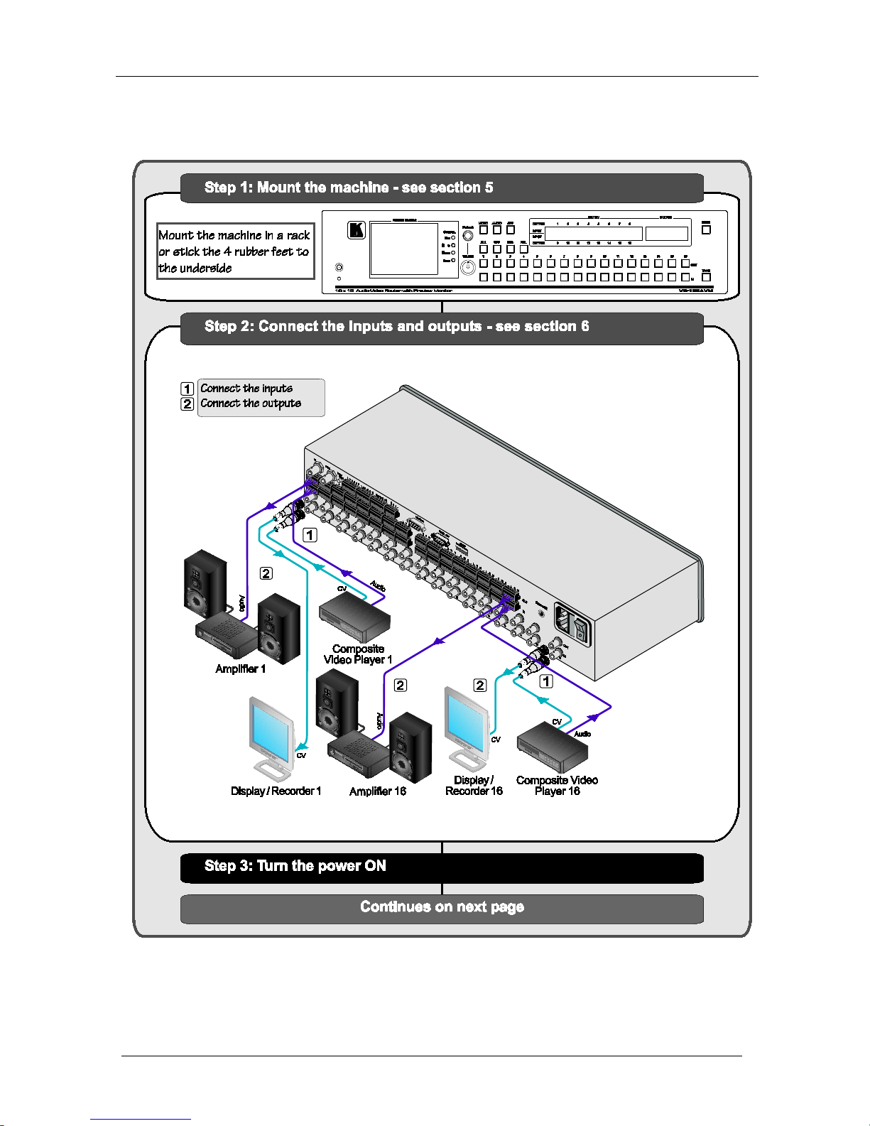
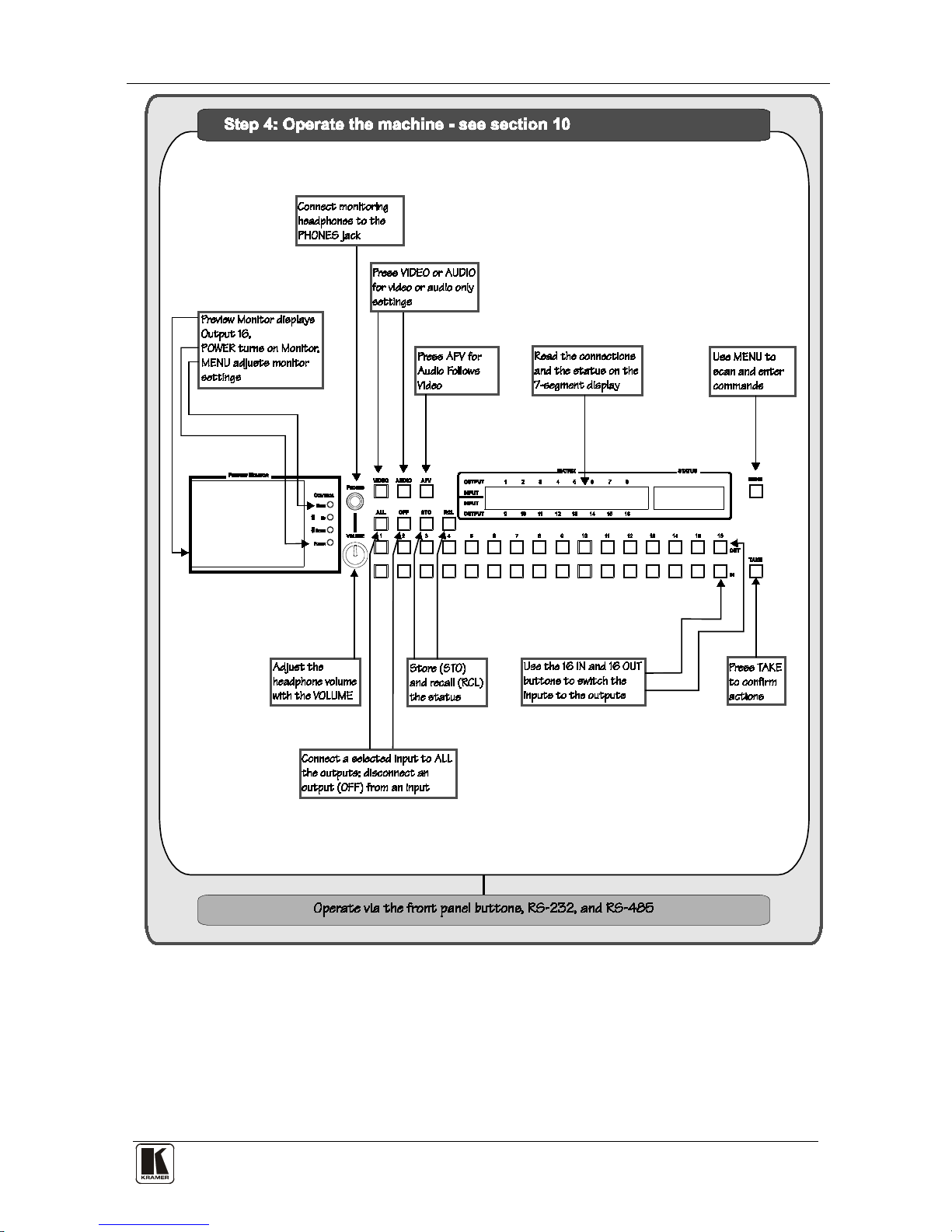
2.1 Quick Start
This quick start chart summarizes the basic setup and operation steps.
Getting Started
3

KRAMER: SIMPLE CREATIVE TECHNOLOGY
Overview
4
3 Overview
The VS-162AVM is a high-performance 16x16 vertical interval matrix
switcher for composite video signals on BNC connectors, and balanced stereo
audio signals on detachable terminal block connectors.
The VS-162AVM forms part of the series of 16x16 matrix switchers that
includes, but is not limited to, the VS-1616A (a 16x16 analog balanced
stereo audio matrix switcher), and VS-162V (a 16x16 video matrix
switcher).
In particular, the VS-162AVM features:
• A built-in high-quality 3.5-inch LCD display and audio
headphone output with volume control to conveniently monitor
the video and audio of any channel before and after switching
• Excellent video performance, which ensures that it remains
transparent in almost any video application
• Broadcast-quality specifications for audio bandwidth and levels,
and video bandwidth extends to well over 90MHz making the unit
suitable for all video and audio applications
• Multiple SYNC options that make it appropriate for a wide range
of applications with glitch-free transitions. It produces glitch-free
transitions, when sources share a common reference sync
1
In addition the VS-162AVM:
• Can be configured into a Kramer multi-signal switcher system
including digital and analog video, digital and analog audio, and
RS-422 control switchers
• When integrated in a system, all units switch in true audio-follow-
video mode
• Both audio-follow-video and breakaway modes are available
• Recalls up to 60 configuration setups via the non-volatile memory
and provides for an unlimited quantity of setups when using the
Kramer control software on your PC
• Includes an alphameric LCD display to clearly view the switching
status and operate the menus and setup
• With its FLASH memory, lets you upgrade to the latest Kramer
firmware version via Internet download
1 As it switches during the vertical interval

Your Audio-Video Router
5
The VS-162AVM can be controlled:
• Using the front panel buttons
• Remotely, by RS-485 or RS-232 serial commands transmitted by
a touch screen system, PC, or other serial controller
• Remotely, from the Kramer RC-IR3 Infrared Remote Control
Transmitter
• Via external contact closure push buttons
To achieve the best performance:
• Use only good quality connection cables
1
• Avoid interference from neighboring electrical appliances that
may adversely influence signal quality and position your Kramer
VS-162AVM away from moisture, excessive sunlight and dust
to avoid interference,
deterioration in signal quality due to poor matching, and elevated
noise levels (often associated with low quality cables).
4 Your Audio-Video Router
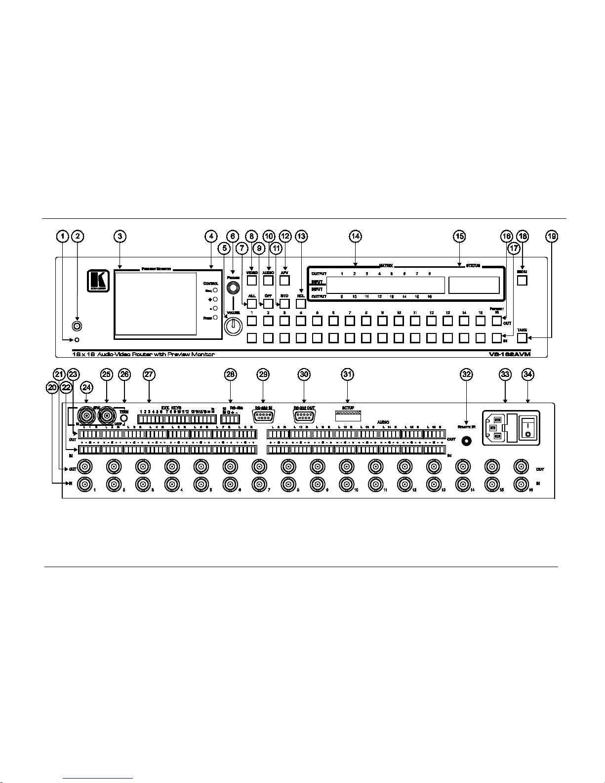
Figure 1 illustrates the front and rear panels of the VS-162AVM. Table 1
and
Table 2 define the front and rear panels of the unit.
1 Available from Kramer Electronics on our Web site at http://www.kramerelectronics.com
KRAMER: SIMPLE CREATIVE TECHNOLOGY
Your Audio-Video Router
6
Figure 1: VS-162AVM 16x16 Audio-Video Router with Preview Monitor
Your Audio-Video Router
7 7
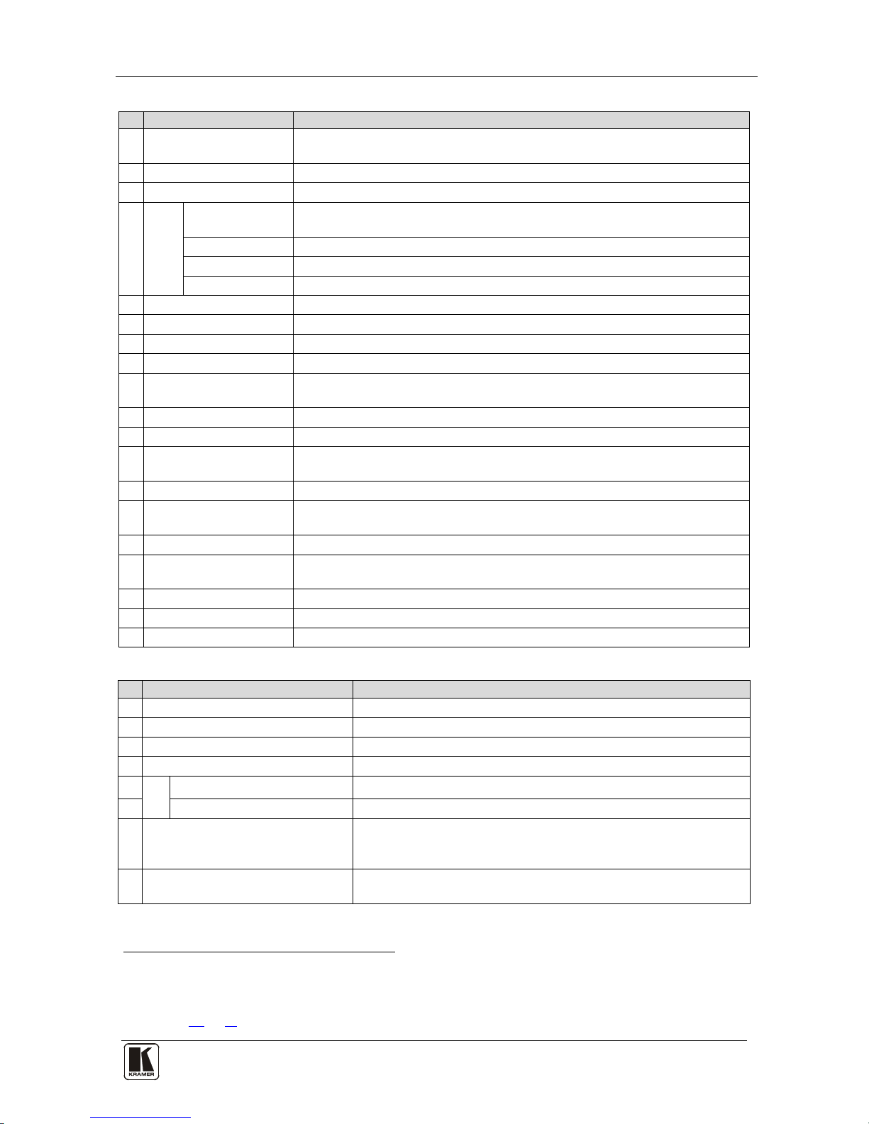
Table 1: Front Panel Features
#
Feature
Function
1 IR Receiver LED The red LED illuminates when receiving signals from the Kramer infrared
remote control transmitter
2 IR Receiver Receives signals from the Kramer infrared remote control transmitter
3 Preview Monitor Displays the video routed to output 16
4
LCD
CONTROL
MENU Button Press once to display the last LCD settings (brightness, contrast, saturation,
and sharpness), each additional press scrolls through the menu items
+ Button Increases the selected setting
– Button Decreases the last setting
POWER Button Turns the LCD display on and off
5 VOLUME Knob Adjusts the audio level of the headphones
6 PHONES ¼” Connector Jack for connecting the headphones to audio 16 output
7 ALL Button Pressing ALL followed by an INPUT button, connects that input to all outputs
8 VIDEO Button When selected
1
9
actions relate to video independently from audio
OFF Button An OFF-OUT combination disconnects that output from the inputs; an OFF-
ALL combination disconnects all the outputs
10 AUDIO Button When selected
2
11
actions relate to audio independently from video
STO Button Stores the current setting in the non-volatile memory
12 AFV Button When selected actions relate to video and audio channels. Audio channels
follow the video channels, and the AFV button is illuminated
13 RCL Button Recalls a setup from the non-volatile memory
14 LCD MATRIX Display3Displays the selected input(s) switched to the output(s) (above or below the
corresponding OUTPUT label) and user interface messages
15 LCD STATUS Display 3 Displays the matrix status
16 OUT Buttons Select the output to which the input is switched (1 to 15)
Preview/16 connects the input to the preview monitor
17 IN Buttons Select the input to switch to the output (1 to 16)
18 MENU Button Recall and navigate the menu points for matrix setting
19 TAKE Button Used to confirm and complete setup and switching
Table 2: Rear Panel Features
#
Feature
Function
20 IN BNC Connectors Connect to the video sources
21 OUT BNC Connectors Connect to the video acceptors
22 IN Terminal Blocks Connect to the audio sources
23 OUT Terminal Blocks Connect to the audio acceptors
24
SYNC
IN BNC Connector Connect to the external video sync source
25 LOOP BNC Connector Connect to the SYNC IN connector on the next unit
26 TERM Button
Press to terminate at 75Ω or release for looping (push in to
terminate the sync line. Release when the sync line extends to
another unit)
27 EXT. (extension) KEYS Terminal
Block Connectors
Connect to an external keyboard (remote unit)
1 The VIDEO button is illuminated when the video breakaway mode is selected
2 The AUDIO button is illuminated when the audio breakaway mode is selected
3 In sections 10
and 11, the word “Displays” refers to the LCD MATRIX and STATUS displays
KRAMER: SIMPLE CREATIVE TECHNOLOGY
Your Audio-Video Router
8
#
Feature
Function
28 RS-485 Detachable Terminal
Block Port
PINS # 1 and # 2 are for vertical sync and Ground connection, and
PINS # 3 and # 4 are for RS 485
29 RS-232 IN 9-pin D-sub (F) Port Connect to the PC or the Remote Controller
1
30 RS-232 OUT 9-pin D-sub (M) Port Connect to the RS-232 IN 9-pin D-sub (F) port of the next unit in
the daisy-chain connection
31 SETUP DIP-switches DIP-switches for setup of the unit
32 REMOTE IR 3.5mm Mini Jack Connect to an external IR receiver unit for controlling the machine via
an IR remote controller (instead of using the front panel IR receiver)
2
33 Power Connector with Fuse AC connector enabling power supply to the unit
34 Power Switch Illuminated switch supplying power to the unit
4.1 Using the IR Transmitter
You can use the RC-IR3 IR transmitter to control the machine via the built-
in IR receiver on the front panel or, instead, via an optional external IR
receiver
3
. The external IR receiver can be located 15 meters away from the
machine. This distance can be extended to up to 60 meters when used with
three extension cables
4
Before using the external IR receiver, be sure to arrange for your Kramer
dealer to insert the internal IR connection cable
13F
5
with the 3.5mm connector
that fits into the REMOTE IR opening on the rear panel. Connect the
external IR receiver to the REMOTE IR 3.5mm connector.
1 If the unit is not the first unit in the line, connects to the RS-232 OUT 9-pin D-sub (F) port of the previous unit in the line
2 Optional. Can be used instead of the front panel (built-in) IR receiver to remotely control the VS-162AVM (only if the
internal IR connection cable has been installed) (See section
4.1)
3 Model: C-A35M/IRR-50
4 Model: C-A35M/A35F-50
5 P/N: 505-70434010-S
Installing the VS-162AVM in a Rack
9 9
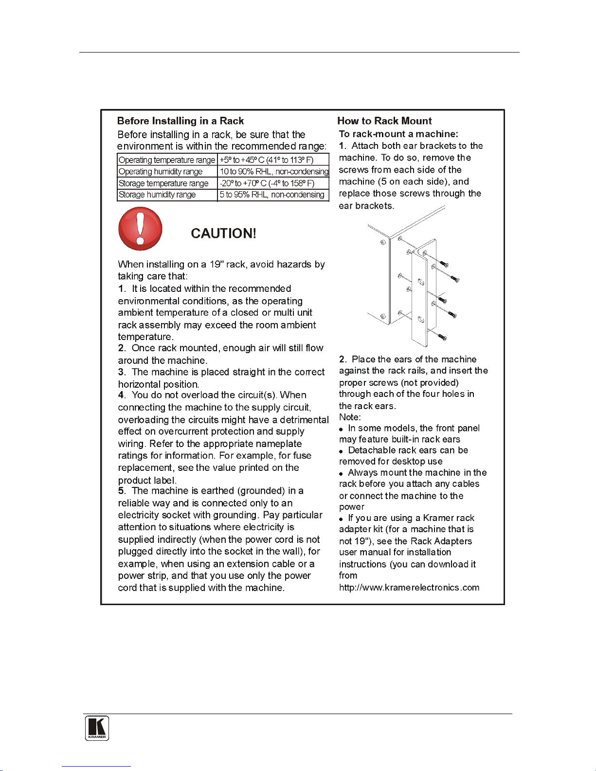
5 Installing the VS-162AVM in a Rack
.
This section provides instructions for rack mounting the unit.
KRAMER: SIMPLE CREATIVE TECHNOLOGY
Installing and Operating a Single VS-162AVM
10
6 Installing and Operating a Single VS-162AVM
To install the VS-162AVM, connect the following
1
• Video input and output cables
to the rear panel, as
required:
• Audio input and output cables
• Control interface cables between switcher units, or PC (or other
controller), as section
9 describes
• Set the DIP-switches, as section
8.1 describes
• Power cord
• Set the system variables using the MENU function, as section
11
describes
By default, the VS-162AVM is setup for use as a single machine. This
means that it is:
• A 16x16 composite video switcher and a 16x16 balanced stereo
audio switcher are set to function by default, in the audio-followvideo mode
• Switched during the vertical interval of the external reference
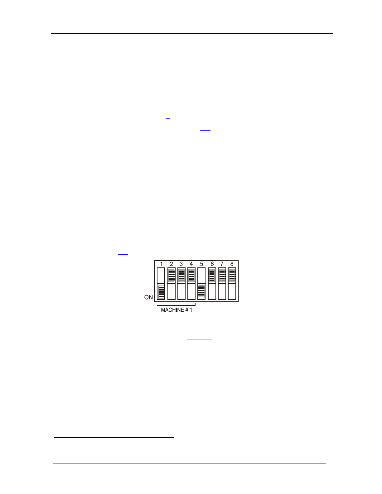
In particular, be sure that the DIP-switches are set as
Figure 2 illustrates
(see section
8.1 for further details):
Figure 2: Default DIP-Switch Setup on a Single Machine
To operate a single machine, see Table 3.
1 Switch OFF the power on each device before connecting it to your unit
Configuring the VS-162AVM
11 11
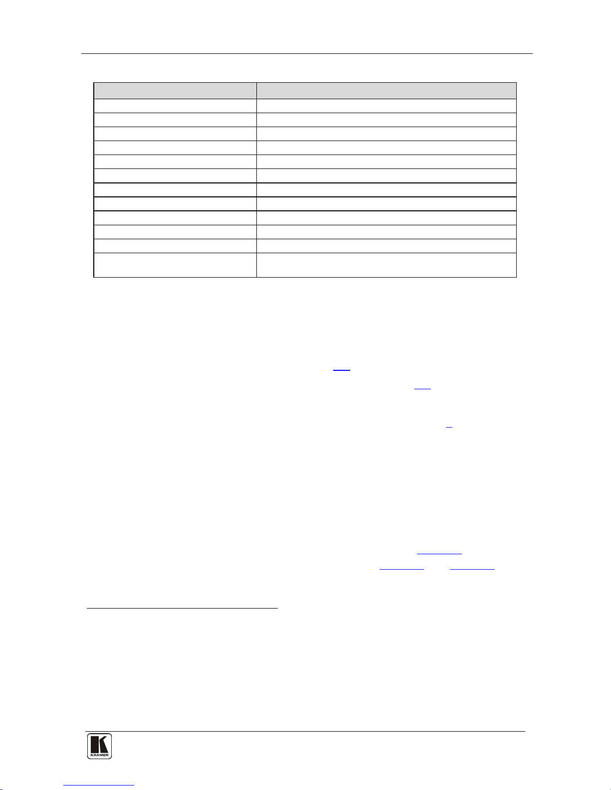
Table 3: Quick Reference Operating Guide for a Single Machine
To perform this command: Press:
Set breakaway mode
1
VIDEO
Set breakaway mode
2
AUDIO
Set audio-follow-video mode
3
AFV
Connect an input with an output OUT #; IN #
Clear (disconnect) a specific output OUT #; OFF
Clear (disconnect) all outputs ALL; OFF
Connect all outputs to a specific input ALL; IN #
Store a setup STO; OUT #; TAKE
Recall a setup RCL; OUT #; TAKE
Lock front panel MENU; TAKE
Unlock front panel TAKE; TAKE
Change default setup Press the Menu button several times until you reach the
appropriate Menu setup command and follow the instructions
7 Configuring the VS-162AVM
Using the VS-162AVM unit and/or other 16x16 matrix switchers in the
series
4
• A standalone switcher (see section
, you can assemble the following kinds of systems:
7.1)
• A system of interconnected switchers (see section
7.2)
Note: When configuring multiple units, each unit must have an address. For
an explanation on addressing and system modes, see section
8.
7.1 Configuring a Standalone Switcher
By default, a single VS-162AVM unit is configured for:
• Composite video with 16 inputs and 16 outputs on BNC
connectors, and
• Balanced stereo audio with 16 inputs and 16 outputs on
detachable terminal block connectors, as shown in
Figure 4 (to
configure for unbalanced
5
Figure 5 stereo audio, see and Figure 6)
1 All operations and the LCD MATRIX display relate to the video channel (independently from audio)
2 All operations and the LCD MATRIX display relate to the audio channel (independently from video)
3 All operations and the LCD MATRIX display relate to both the video and the audio channels. Audio channels follow the
video channels
4 Including the VS-1616A (a 16x16 analog balanced stereo audio matrix switcher)
5 However, for an unbalanced stereo audio input, the output is always half of the input signal. For example, if the input is
6dB, the output is 0dB
KRAMER: SIMPLE CREATIVE TECHNOLOGY
Configuring the VS-162AVM
12
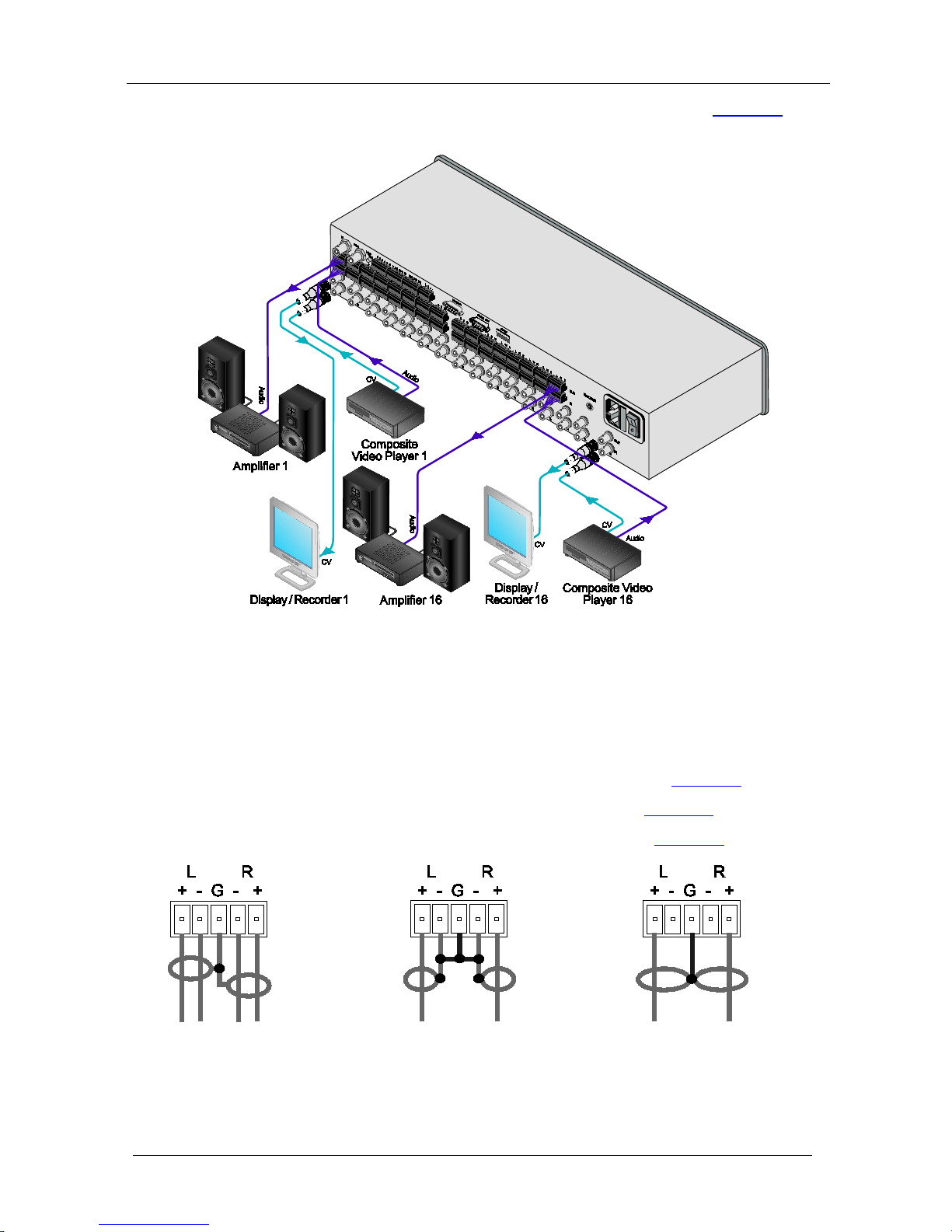
Configure your VS-162AVM unit as a standalone switcher, as Figure 3
illustrates:
Figure 3: Configuring the VS-162AVM as a Standalone Switcher
7.2 Connecting the Balanced/Unbalanced Stereo Audio
Input/Output
This section illustrates how to connect:
• A balanced stereo audio input/output connection, see
Figure 4
• An unbalanced stereo audio input connection, see
Figure 5
• An unbalanced stereo audio output connection, see
Figure 6
Figure 4: Connecting the
Balanced Stereo Audio
Input/Output
Figure 5: Connecting the
Unbalanced Stereo
Audio Input
Figure 6: Connecting an
Unbalanced Stereo
Audio Output
Configuring the VS-162AVM
13 13
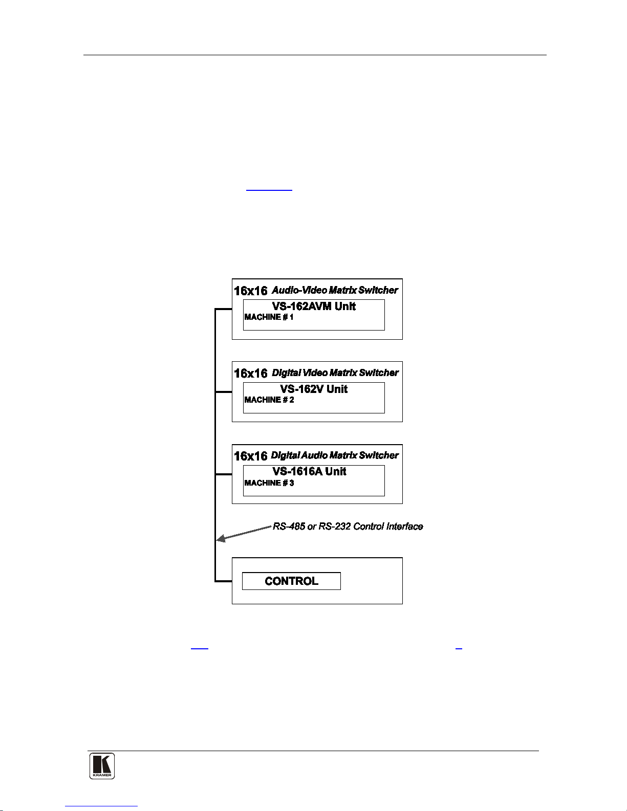
7.3 Assembling a System of Interconnected Switchers
A major advantage of the VS-162AVM is that it belongs to the series of
16x16 matrix switchers and, as such, can interconnect with other switchers
in the series. This series includes, but is not limited to, the VS-1616A (a
16x16 analog balanced stereo audio matrix switcher), and VS-162V (a
16x16 video matrix switcher).
The block diagram in
Figure 7
illustrates how to assemble an interconnected
varied-format 16x16 series switcher that consists of a 16x16 Audio-Video
Router with Preview Monitor (MACHINE # 1), a 16x16 digital video
matrix switcher (MACHINE # 2), and a 16x16 digital audio matrix switcher
(MACHINE # 3). Each switcher has a unique MACHINE #. Control of the
system is via the MACHINE #.
Figure 7: Assembling a System of Interconnected Switchers
See section 8.1 for how to set the DIP-switches, and section 9 for how to
control this group of interconnected varied-format 16x16 series switchers,
and other configurations.
 Loading...