

Kramer VS-162AV, VS-162AVRCA User Manual

Kramer Electronics, Ltd.
USER MANUAL
Models:
VS-162AV, 16x16 Audio-Video Matrix Switcher
VS-162AVRCA, 16x16 Audio-Video Matrix Switcher

Contents
i
Contents
1 Introduction 1
2 Getting Started 1
3 Overview 2
4 Summary of how to Operate a Single Machine 3
5 Your Audio-Video Matrix Switcher 4
6 Installing the Audio-Video Matrix Switcher 8
6.1 Configuring a Stand Alone Switcher 8
6.1.1 Connecting a Balanced Stereo Audio Input / Output (VS-162AV) 9
6.1.2 Connecting an Unbalanced Stereo Audio Input / Output (VS-162AV) 9
6.2 Assembling a System of Interconnected Switchers 10
6.3 Dipswitch Settings 11
6.3.1 Setting the MACHINE # 11
6.3.2 Understanding the SYSTEM Mode 12
6.3.3 Understanding the SLAVE Mode 13
6.4 Connecting a Control Interface 13
6.4.1 Connecting the RS-232 Control Interface 14
6.4.1.1 Connecting 2 Units using a Null-modem Adapter 15
6.4.1.2 Connecting 2 Units without using a Null-modem Adapter 15
6.4.1.3 PC DB9 COM Port Connection to a Unit with a Null-modem Adapter 15
6.4.1.4 PC DB9 COM Port Connection to a Unit with no Null-modem Adapter 15
6.4.1.5 PC DB25 COM Port Connection to a Unit 16
6.4.2 Connecting the RS-485 Control Interface 16
6.5 Configuring the Sync 18
6.6 Connecting the KEYBOARD EXTENSION 19
7 Operating Your Audio-Video Matrix Switcher 20
7.1 Startup Display 20
7.2 Using the Front Panel Buttons 20
7.2.1 Choosing the Audio-Follow-Video or Breakaway Mode 21
7.2.1.1 Setting the Breakaway Mode 21
7.2.1.2 Setting the Audio-Follow-Video Mode 21
7.2.2 Confirming Settings 22
7.2.2.1 Toggling between the AT ONCE and CONFIRM Modes 22
7.2.3 Switching 23
7.2.3.1 Switching one Input to one Output 23
7.2.3.2 Switching several Inputs to several Outputs 24
7.2.3.3 Switching one Input to all Outputs 25
7.2.4 Clearing 26
7.2.4.1 Clearing an Output 26
7.2.4.2 Clearing several Outputs 27
7.2.4.3 Clearing all Outputs 28
7.2.5 Storing and Recalling Setups 29
7.2.5.1 Storing Setups 29
7.2.5.2 Recalling Setups 30

KRAMER: SIMPLE CREATIVE TECHNOLOGY
Contents
ii
8 MENU Commands Sequence 31
8.1 Locking and Unlocking the Front Panel 32
8.2 Choosing the Follow-System or Breakaway-From-System Mode 33
8.3 Choosing the SWITCHING METHOD Setting 35
8.3.1 Understanding the SWITCHING METHOD Settings 35
8.3.2 Configuring a SWITCHING METHOD 36
8.4 Choosing the extended Keyboard Setting 37
8.5 Setting the STORE/RECALL KEYBOARD Mode 37
8.6 Choosing what to INDICATE 38
8.7 Choosing the COMMUNICATION Setting 39
8.8 Setting the IR REMOTE Control 40
8.9 Choosing the AUTO STORE Current SETUP 41
8.10 Identifying the MACHINE 41
8.11 Choosing the initial RESET 42
9 Flash Memory Upgrade 43
9.1 Connecting the PC to the RS-232 Port 43
9.2 Upgrading Firmware 43
10 Technical Specifications 46
11 Communication Protocol 46

Contents
iii
Figures
Figure 1: Default Dipswitch Setup on a Single Machine 3
Figure 2: VS-162AV 16x16 Audio-Video Matrix Switcher 5
Figure 3: VS-162AVRCA 16x16 Audio-Video Matrix Switcher
6
Figure 4: Configuring the VS-162AV as a Stand Alone Switcher
9
Figure 5: Connecting a Balanced Stereo Audio Input # 1
9
Figure 6: Connecting an Unbalanced Stereo Audio Input # 1 9
Figure 7: Assembling a System of Interconnected Switchers
10
Figure 8: Rear Panel Dipswitches
11
Figure 9: Connecting a PC to 4 Units
14
Figure 10: Connecting a PC (with a 25-pin connector) without a Null-modem Adapter 16
Figure 11: RS-485 Connector PINOUT
16
Figure 12: Connecting the RS-485 Connectors
17
Figure 13: An RS-485 Control Interface Setup
18
Figure 14: Keyboard Extension (EXT. KEYS) Connector
19
Figure 15: Default Startup Status Display Sequence 20
Figure 16: Sequence of MENU Commands
31
Figure 17: Choosing the MTX (SYNC from Matrix) Setting
36
Figure 18: Choosing what to INDICATE
38
Figure 19: Machine Identification 42
Tables
Table 1: Quick Reference Operating Guide for a Single Machine 4
Table 2: Front Panel Unit Features
7
Table 3: Rear Panel Unit Features
7
Table 4: Dipswitch Definitions
11
Table 5: Machine # Dipswitch Settings 12
Table 6: Summary of Basic IR-1 Setups
40
Table 7: Summary of Basic IR-1 Operations
40
Table 8: Technical Specifications of VS-162AV / VS-162AVRCA
46
Table 9: Hex Table for the VS-162AV / VS-162AVRCA Audio-Video Matrix Switcher 47

Introduction
1 1
1 Introduction
Welcome to Kramer Electronics (since 1981): a world of unique, creative and
affordable solutions to the infinite range of problems that confront the video, audio
and presentation professional on a daily basis. In recent years, we have redesigned
and upgraded most of our line, making the best even better! Our 350-plus
different models now appear in 8 Groups
1
• Any professional system requiring outstanding value in a 16x16
matrix
, which are clearly defined by function.
Congratulations on purchasing your Kramer: VS-162AV 16x16 Audio-Video
Matrix Switcher, and/or VS-162AVRCA 16x16 Audio-Video Matrix
Switcher, which are ideal for the following typical applications:
• Production and duplication facilities
• Rental/staging applications
• Security, CCTV, and home theater systems
The package includes the following items:
• VS-162AV 16x16 Audio-Video Matrix Switcher or VS-162AVRCA
16x16 Audio-Video Matrix
• Power cord
• Windows®-based control software
• Null-modem adapter
• This user manual
2
• Kramer Infra-Red Remote Control Transmitter (including the
required battery and a separate user manual
2
)
2 Getting Started
We recommend that you:
• Unpack the equipment carefully and save the original box and
packaging materials for possible future shipment
• Review the contents of this user manual
• Use Kramer high performance high resolution cables
1 GROUP 1: Distribution Amplifiers; GROUP 2: Switchers and Routers; GROUP 3: Video, Audio, VGA/XGA Processors;
GROUP 4: Interfaces and Sync Processors; GROUP 5: Twisted Pair Interfaces; GROUP 6: Accessories and Rack Adapters;
GROUP 7: Scan Converters and Scalers; and GROUP 8: Cables and Connectors
2 Download up-to-date Kramer user manuals from the Internet at: http://www.kramerelectronics.com

KRAMER: SIMPLE CREATIVE TECHNOLOGY
Overview
2
3 Overview
The VS-162AV is a high performance 16x16 vertical interval matrix switcher
for composite video signals on BNC connectors, and balanced stereo audio
signals on detachable terminal block connectors. The VS-162AVRCA is a high
performance 16x16 vertical interval matrix switcher for composite video signals
on BNC connectors, and unbalanced stereo audio signals on RCA connectors.
A main advantage of the VS-162AV / VS-162AVRCA is that it forms part of
the series of 16x16 matrix switchers that includes, but is not limited to,
VS-1616SDI (a 16x16 digital Video Matrix Switcher), VS-1616AD (a 16x16
digital audio matrix switcher), VS-1616V (a 16x16 analog video matrix
switcher), VS-1616A (a 16x16 analog balanced stereo audio matrix switcher),
and VS-162V (a 16x16 video matrix switcher).
In particular, the VS-162AV / VS-162AVRCA:
• Has multiple SYNC options that make it appropriate for a wide
range of applications with glitch-free transitions. It produces glitch-free
transitions, when sources share a common reference sync
1
• Offers excellent video performance, which ensures that it remains
transparent in almost any video application
• Video bandwidth extends to well over 90 MHz, making it suitable
for all video applications while audio bandwidth and levels conform to
broadcast specifications for audio applications
In addition the VS-162AV / VS-162AVRCA:
• Can be configured into a Kramer multi-signal switcher system
including digital and analog video, digital and analog audio, and RS-422
control switchers
• When integrated in a system, all units switch in true audio-follow-video
mode
• Both audio-follow-video and breakaway modes are available
• Recalls up to 60 configuration setups via the non-volatile memory
and provides for an unlimited quantity of setups when using the Kramer
control software on your PC
• Includes a user-friendly LCD display (making operation even easier)
• With its FLASH memory, lets you upgrade to the latest Kramer
firmware version via Internet download
• Comes with a choice of protocol format: hexadecimal or ASCII
Control the VS-162AV / VS-162AVRCA:
1 As it switches during the vertical interval
Summary of how to Operate a Single Machine
3 3
• Using the front panel buttons
• Remotely, by RS-485 or RS-232 serial commands transmitted by a
touch screen system, PC, or other serial controller
• Remotely, from the Kramer RC-IR1 Infra-Red Remote Control
Transmitter
1
• Via external dry-contact push buttons
Note: From here onward, “unit” refers to the “VS-162AV / VS-162AVRCA”.
On the VS-162AV, the audio signals are balanced stereo signals on
detachable terminal block connectors. On the VS 162AVRCA, the audio
signals are unbalanced stereo signals on RCA connectors.
To achieve the best performance:
• Connect only good quality connection cables, thus avoiding
interference, deterioration in signal quality due to poor matching, and
elevated noise levels (often associated with low quality cables)
• Avoid interference from neighboring electrical appliances that may
adversely influence signal quality and position your unit in a location
free from moisture and away from excessive sunlight and dust
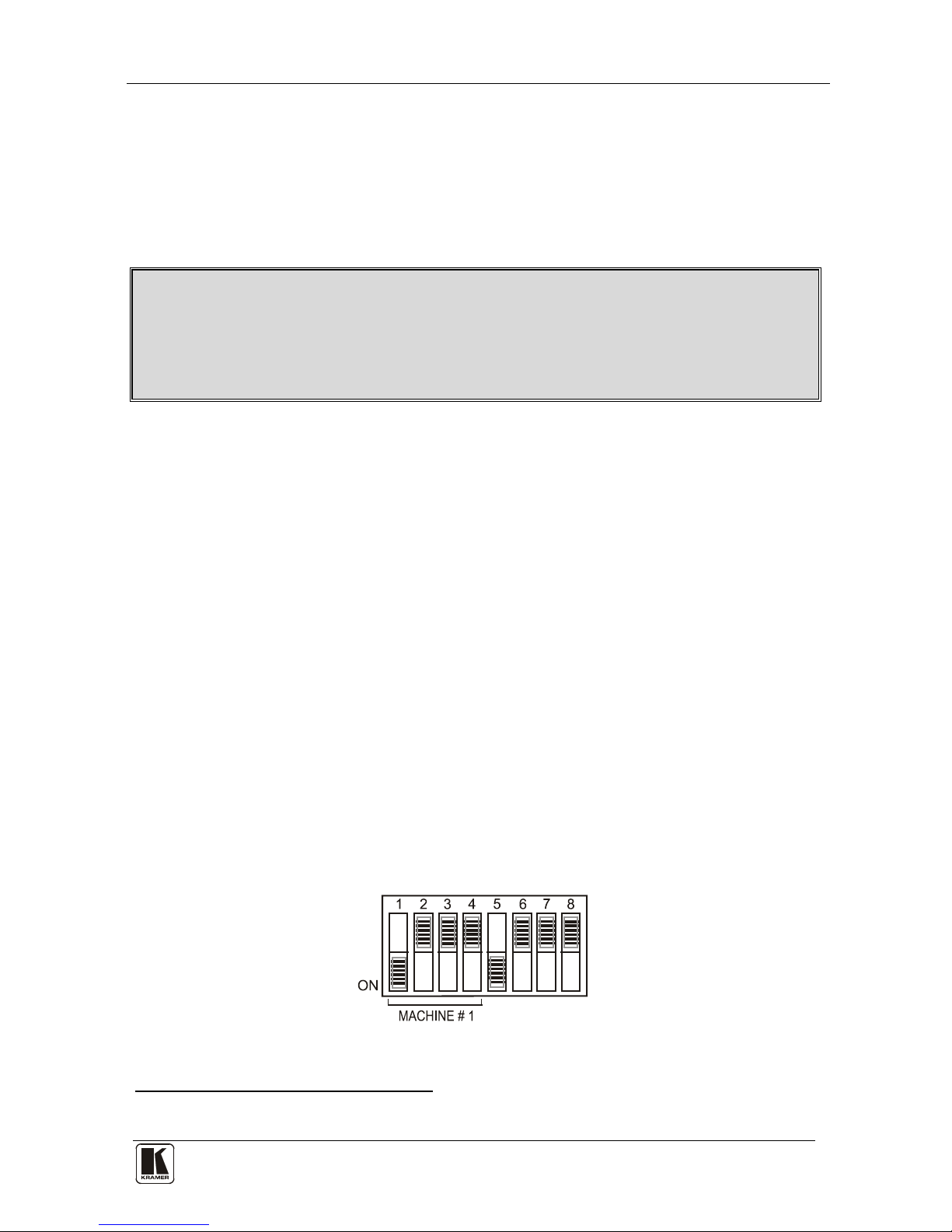
4 Summary of how to Operate a Single Machine
By default, the 16x16 Audio-Video Matrix Switcher is setup for use as a
single machine. This means that it is:
• A 16x16 composite video switcher and a 16x16 balanced stereo audio
switcher (VS-162AV)/16x16 unbalanced stereo audio switcher
(VS-162AVRCA), set to function by default, in the audio-follow-video
mode
• Switched during the vertical interval of the external reference
In particular, be sure that the dipswitches are set as Figure 1 illustrates (see
section 6.3 for further details):
Figure 1: Default Dipswitch Setup on a Single Machine
1 Previously known as the IR-1 / IR-1-01
KRAMER: SIMPLE CREATIVE TECHNOLOGY
Your Audio-Video Matrix Switcher
4
To operate a single machine, see Table 1.
Table 1: Quick Reference Operating Guide for a Single Machine
To perform this command: Press:
Set breakaway mode
1
VIDEO
Set breakaway mode
2
AUDIO
Set audio-follow-video mode
3
AFV
Connect an input with an output OUT #; IN #
Clear (disconnect) a specific output OUT #; OFF
Clear (disconnect) all outputs ALL; OFF
Connect all outputs to a specific input ALL; IN #
Store a setup STO; OUT #; TAKE
Recall a setup RCL; OUT #; TAKE
Lock front panel MENU; TAKE
Unlock front panel TAKE; TAKE
Change default setup Press the Menu button several times until
you reach the appropriate Menu setup
command and follow the instructions
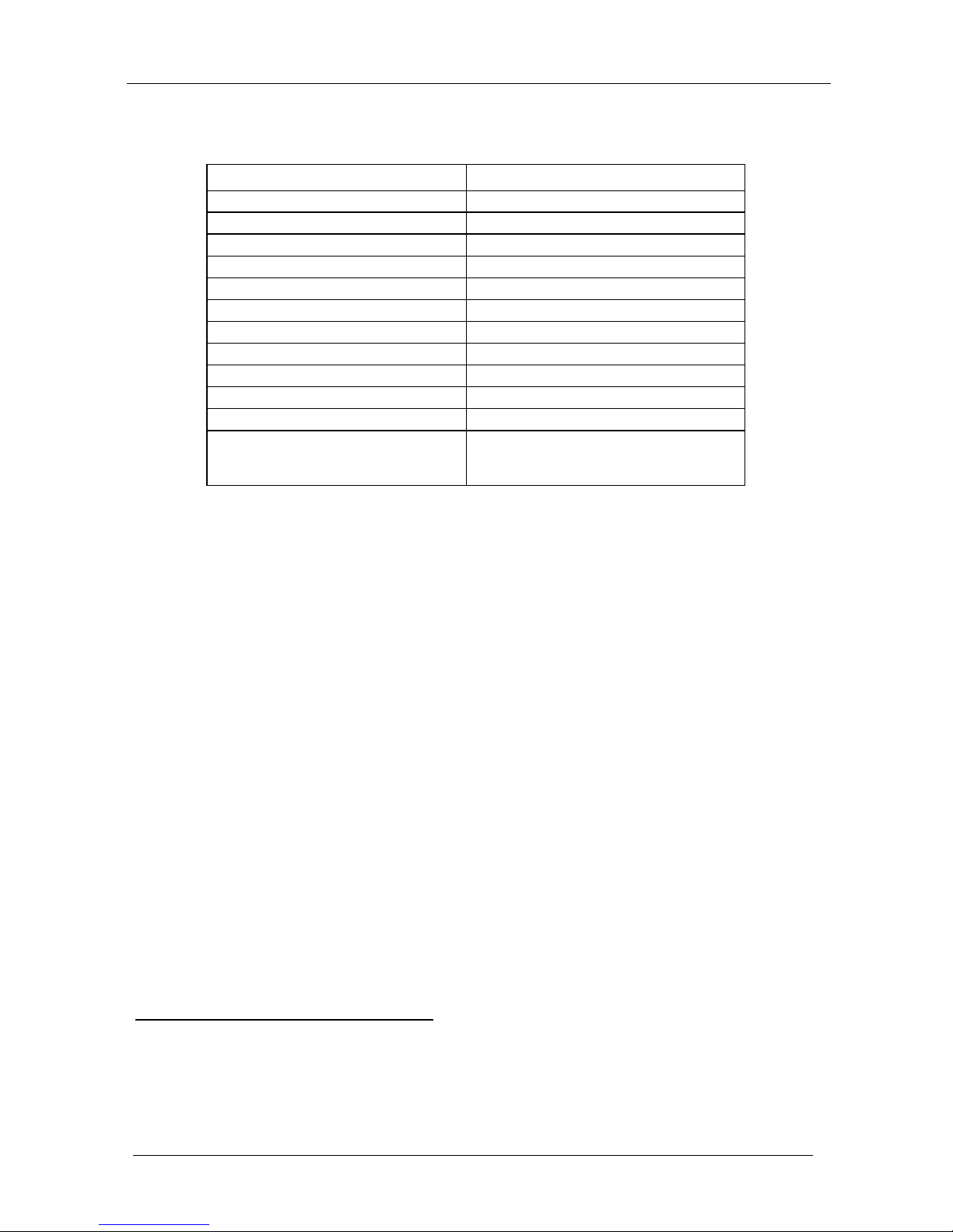
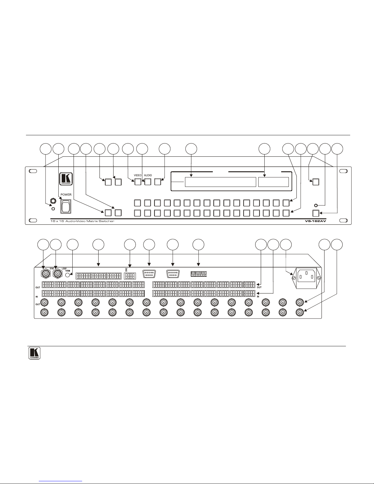
5 Your Audio-Video Matrix Switcher
Figure 2 illustrates the front and rear panels of the VS-162AV. Figure 3
illustrates the front and rear panels of the VS-162AVRCA. Table 2 and Table
3 define the front and rear panels of the unit.
1 All operations and the LCD MATRIX Display relate to the video channel (independently from audio)
2 All operations and the LCD MATRIX Display relate to the audio channel (independently from video)
3 All operations and the LCD MATRIX Display relate to both the video and the audio channels. Audio channels follow the
video channels
Your Audio-Video Matrix Switcher
5
STATUSMATRIX
ALL OFF
STO RCL
AFV
OUT
IN
OUTPUT
OUTPUT
1122334
4
556
677
889
91010111112121313141415151616
INPUT
INPUT
TAKE
MENU
9
10
11
12
13
14 15
16
2
3
5
4
6
7
8
1
1 2 3 4 5 6 7 8 9 10 11 12 13 14 15 16
IN
+ - G - ++ - G - + + - G - + + - G - + + - G - + + - G - + + - G - + + - G - +
20
22
23
2421
AUDIO
L R10L R9 L R11 L R12 L R13 L R14 L R15 L R16
RS-232 OUT SE TUP
IN
RS-232 INRS-485
+ -
G
OUT
1 2 3 4 5 6 7 8 9 10 11 12 13 14 15 16
IN
EXT. KEYS
19
28
29
27
25
26
OUT
+ - G - ++ - G - + + - G - + -+ G - + + - G - + + - G - + + - G - + + - G - +
L R2L R1 L R 6 L R7 LR R8L R4 L R5 L3
IN
18
17
Figure 2: VS-162AV 16x16 Audio-Video Matrix Switcher
KRAMER: SIMPLE CREATIVE TECHNOLOGY
Your Audio-Video Matrix Switcher
6
STATUSMATRIX
ALL OFF
STO RCL
AFV
OUT
IN
OUTPUT
OUTPUT
1
1
223
344
5
566
77889
9
1010111112
12
13
13
141415
15
16
16
INPUT
INPUT
TAKE
MENU
9
10
11
12
13
14
15
16
2 3
54
6 7
8
1
20
22
23
24
21
19
27
25
26
18
17
28
29
Figure 3: VS-162AVRCA 16x16 Audio-Video Matrix Switcher
Your Audio-Video Matrix Switcher
7 7
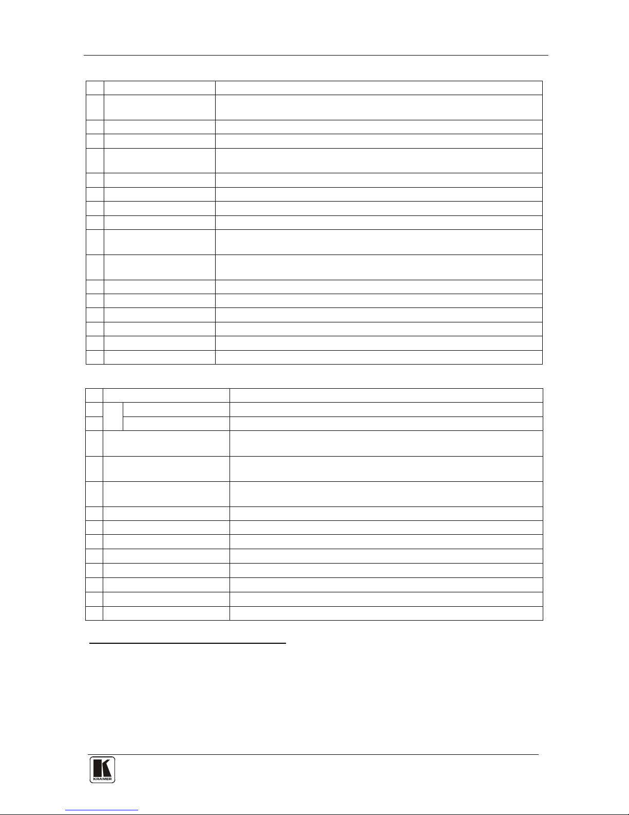
Table 2: Front Panel Unit Features
# Feature Function
1 IR Receiver The red LED is illuminated when receiving signals from the Kramer Infra-
red remote control transmitter
2 POWER Switch Illuminated switch supplying power to the unit
3 ALL Button Pressing ALL followed by an INPUT button, connects that input to all outputs
4 OFF Button An OFF-OUT combination disconnects that output from the inputs; an OFF-
ALL combination disconnects all the outputs
5 STO Button Stores the current setting in the non-volatile memory
6 RCL Button Recalls a setup from the non-volatile memory
7 VIDEO Button When pressed
1
8
actions relate to video independently from audio
AUDIO Button When pressed
2
9
actions relate to audio independently from video
AFV Button When pressed actions relate to video and audio channels. Audio channels
follow the video channels, and the AFV button is illuminated
10 LCD MATRIX Display3Displays the selected input(s) switched to the output(s) (above or below the
corresponding OUTPUT label) and user interface messages
11 LCD STATUS Display3 Displays the matrix status (input to output connections)
12 OUT Buttons Select the output to which the input is switched
13 IN Buttons Select the input to switch to the output
14 MENU Button Selects the programming commands to setup the switcher
15 TAKE LED Shows the current TAKE button mode
16 TAKE Button Used to confirm and complete setup and switching
Table 3: Rear Panel Unit Features
# Feature Function
17
SYNC
IN BNC Connector Connect to the external video sync source
18 LOOP BNC Connector Connect to the SYNC IN connector on the next unit
19 TERM Button
Press to terminate at 75Ω or release for looping (push in to terminate
the sync line. Push out when the sync line extends to another unit)
20 EXT. (extension) KEYS
Terminal Block Connectors
Connect to an external keyboard (remote unit)
21 RS-485 Detachable
Terminal Block Port
PINS # 1 and # 2 are for vertical sync and Ground connection, and PINS #
3 and # 4 are for RS 485
22 RS-232 IN DB 9F Port Connect to the PC or the Remote Controller
4
23 RS-232 OUT DB 9M Port Connect to the RS-232 IN DB9F port of the next unit in the daisy-chain connection
24 SETUP Dipswitches Dipswitches for setup of the unit
25
OUT Connectors
5
Connect to the audio acceptors
6
26
IN Connectors5 Connect to the audio sources6
27 Power Connector with Fuse AC connector enabling power supply to the unit
28 OUT BNC Connectors Connect to the video acceptors
29 IN BNC Connectors Connect to the video sources
1 The VIDEO button is illuminated when the video breakaway mode is selected
2 The AUDIO button is illuminated when the audio breakaway mode is selected
3 In sections
7.2.5 and 8, the word “Displays” refers to the LCD MATRIX and STATUS Displays
4 If the unit is not the first unit in the line, connects to the RS-232 OUT DB 9F port of the previous unit in the line
5 Terminal blocks on the VS-162AV; RCA connectors on the VS-162AVRCA
6 Balanced on the VS-162AV, unbalanced on the VS-162AVRCA

KRAMER: SIMPLE CREATIVE TECHNOLOGY
Installing the Audio-Video Matrix Switcher
8
6 Installing the Audio-Video Matrix Switcher
To install the unit, connect the following
1
• Power cord
to the rear panel, as required:
• Video input and output cables
• Audio input and output cables
• Control Interface cables between switcher units, or PC (or other
controller), as section 6.4 describes
• Set the dipswitches, as section 6.3 describes
• Set the system variables using the MENU function, as section 8
describes
Using the unit and/or other 16x16 matrix switchers in the series
2
• A stand alone switcher (see section
, you can
assemble the following kinds of systems:
6.1)
• A system of interconnected switchers (see section 6.2)
• A multi-channel switcher (see section 6.3.3)
6.1 Configuring a Stand Alone Switcher
By default, a single VS-162AV unit is configured for:
• Composite video with 16 inputs and 16 outputs on BNC connectors,
and
• Balanced stereo audio
3
6.1.1
with 16 inputs and 16 outputs on detachable
terminal block connectors, as section describes (to configure for
unbalanced
4
6.1.2 stereo audio, see section )
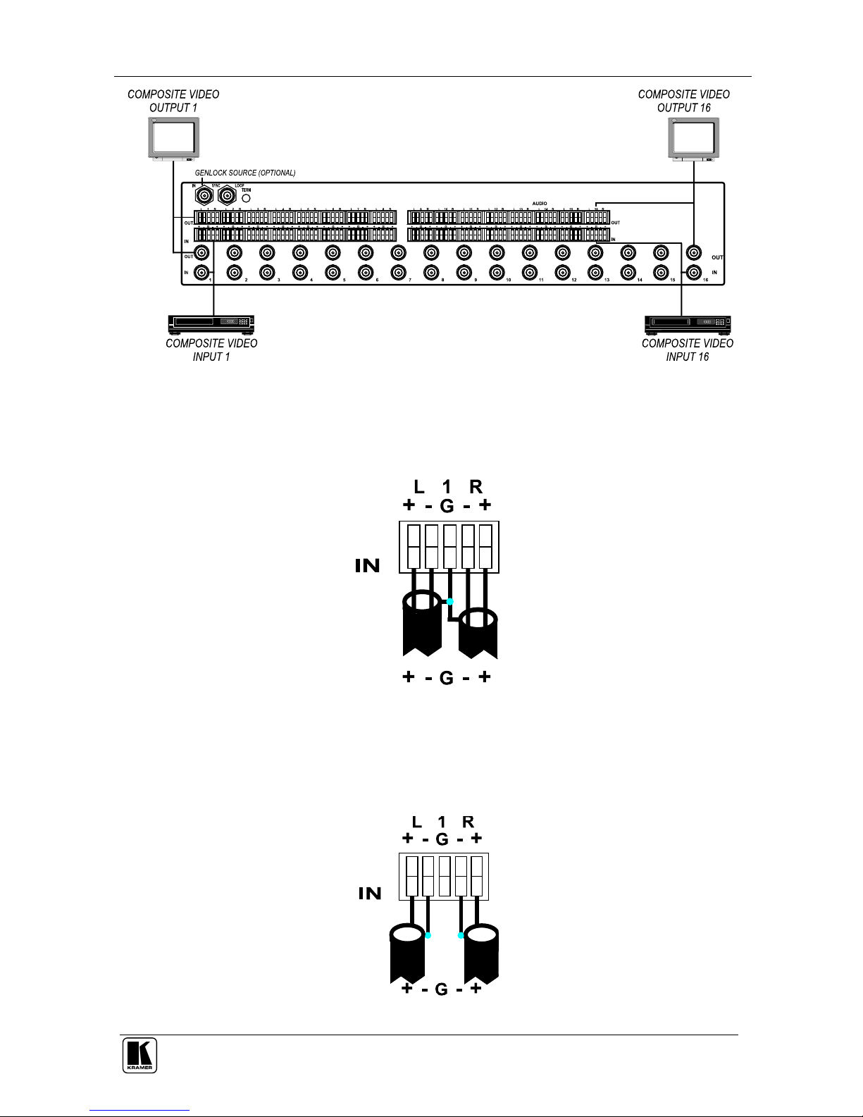
Configure your VS-162AV unit as a stand alone switcher, as Figure 4
illustrates:
1 Switch OFF the power on each device before connecting it to your unit
2 Including the VS-1616SDI (a 16x16 digital video matrix switcher), the VS-1616AD (a 16x16 digital audio matrix switcher),
the VS-1616V (a 16x16 analog video matrix switcher), the VS-1616A (a 16x16 analog balanced stereo audio matrix
switcher), and the VS-162V (a 16x16 video matrix switcher)
3 The VS-162AVRCA (unlike the VS-162AV) is configured for unbalanced stereo audio with 16 inputs and 16 outputs on
RCA connectors
4 However, for an unbalanced stereo audio input, the output will always be half of the input signal. For example, if the input
is 6dB, the output will be 0dB
Installing the Audio-Video Matrix Switcher
9
Figure 4: Configuring the VS-162AV as a Stand Alone Switcher
6.1.1 Connecting a Balanced Stereo Audio Input / Output (VS-162AV)
Figure 5 illustrates a balanced stereo audio input # 1:
Figure 5: Connecting a Balanced Stereo Audio Input # 1
6.1.2 Connecting an Unbalanced Stereo Audio Input / Output
(VS-162AV)
Figure 6 illustrates an unbalanced stereo audio input # 1:
Figure 6: Connecting an Unbalanced Stereo Audio Input # 1
KRAMER: SIMPLE CREATIVE TECHNOLOGY
Installing the Audio-Video Matrix Switcher
10
6.2 Assembling a System of Interconnected Switchers
A major advantage of the unit is that it belongs to the series of 16x16 matrix
switchers and, as such, can interconnect with other switchers in the series.
This series includes, but is not limited to, VS-1616SDI (a 16x16 digital Video
Matrix Switcher), VS-1616AD (a 16x16 digital audio matrix switcher),
VS-1616V (a 16x16 analog video matrix switcher), VS-1616A (a 16x16
analog balanced stereo audio matrix switcher), and VS-162V (a 16x16 video
matrix switcher).
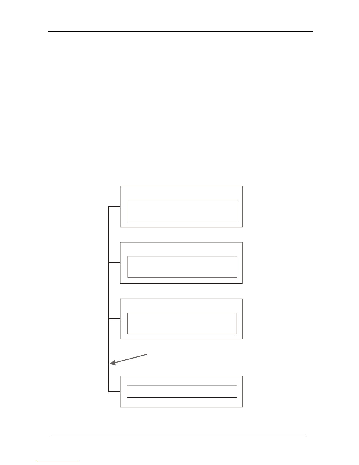
The block diagram in Figure 7 illustrates how to assemble an interconnected
varied-format 16x16 series switcher that consists of a 16x16 audio-video
matrix switcher, a 16x16 digital video matrix switcher, and a 16x16 digital
audio matrix switcher. Each switcher has a unique MACHINE #. In Figure 7,
the 16x16 audio-video matrix switcher is MACHINE # 1, the 16x16 digital
video matrix switcher is MACHINE # 2 and the 16x16 digital audio matrix
switcher is MACHINE #
3. Control of the system is via the MACHINE #’s.
16x16
VS-1616SDI Unit
MACHINE # 2
Digital Video Matrix Switcher
16x16
VS-162AV / VS-162AVRCA Unit
MACHINE # 1
Audio-Video Matrix Switcher
CONTROL
RS-485 or RS-232 Control Interface
16x16
VS-1616AD Unit
MACHINE # 3
Digital Audio Matrix Switcher
Figure 7: Assembling a System of Interconnected Switchers
Installing the Audio-Video Matrix Switcher
11 11
Refer to section 6.3 for details of how to set the dipswitches, and to section
6.4 for details of how to control this group of interconnected varied-format
16x16 series switchers, and other configurations.
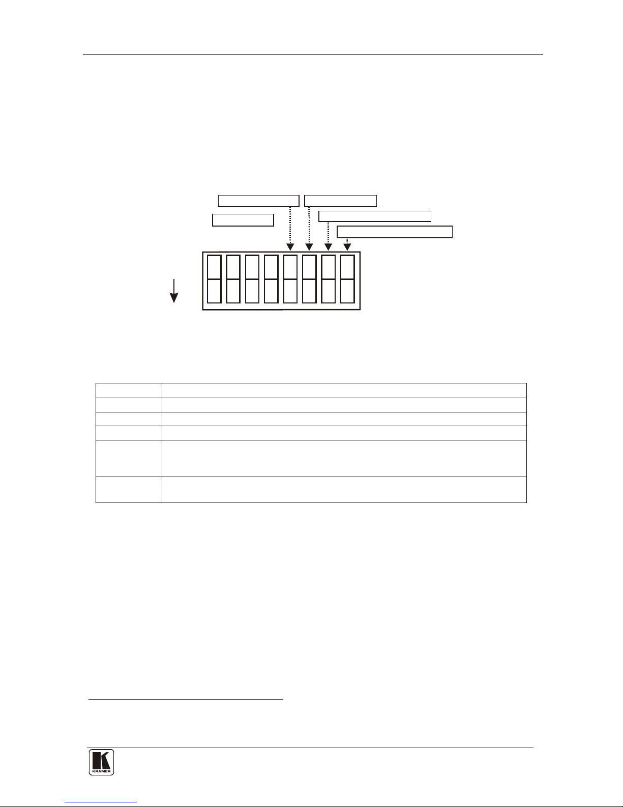
6.3 Dipswitch Settings
Configure the unit by setting the 8 dipswitches as Figure 8 and Table 4
define:
ON
3
5
6
8
}
RS-232 NULL-MODEM
MACHINE #
SYSTEM MODE
SLAVE MODE
RS-485 TERMINATION
Figure 8: Rear Panel Dipswitches
Table 4: Dipswitch Definitions
Dipswitch # Function:
1-4 Set the MACHINE # (see Table 5 in section 6.3.1)
5 Enables (ON) or disables (OFF) the Follow-SYSTEM mode
6 Enables (ON) or disables (OFF) the SLAVE mode in a multi-channel configuration
7 Disables use of a null modem adapter
1
OFF = RS-232 connection via a null modem adapter
ON = RS-232 connection without a null modem adapter
with RS-232
8 RS-485 termination for first and last machine = ON (RS-485 line terminates with
110Ω); for others = OFF (RS-485 line is open)
6.3.1 Setting the MACHINE #
To control a unit via RS-232 or RS-485, each unit has to be identified via its
unique MACHINE #.
Set the MACHINE #
2
Table 5 on a unit according to .
A valid MACHINE # is from 1 to 15.
1 See section 6.4.1
2 When using a single unit, set the unit to MACHINE # 1
KRAMER: SIMPLE CREATIVE TECHNOLOGY
Installing the Audio-Video Matrix Switcher
12
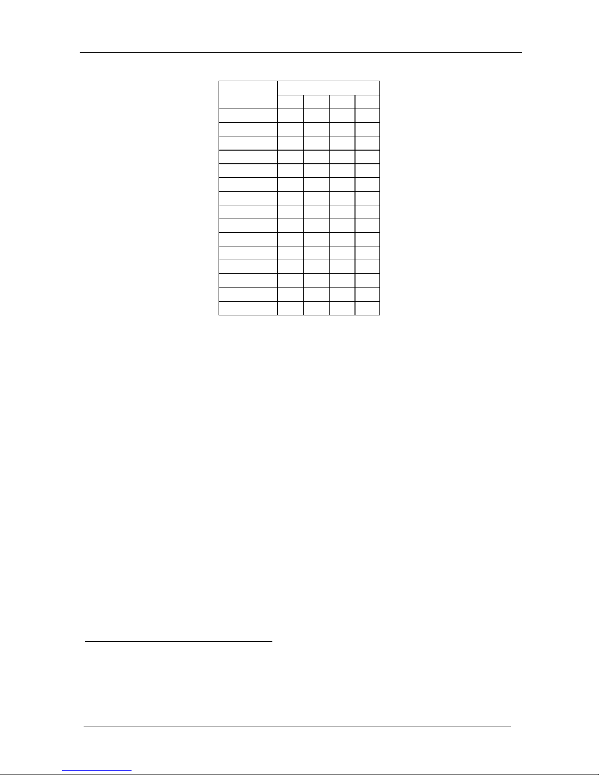
Table 5: Machine # Dipswitch Settings
MACHINE # DIPSWITCH
1 2 3 4
1 ON OFF OFF OFF
2 OFF ON OFF OFF
3 ON ON OFF OFF
4 OFF OFF ON OFF
5 ON OFF ON OFF
6 OFF ON ON OFF
7 ON ON ON OFF
8 OFF OFF OFF ON
9 ON OFF OFF ON
10 OFF ON OFF ON
11 ON ON OFF ON
12 OFF OFF ON ON
13 ON OFF ON ON
14 OFF ON ON ON
15 ON ON ON ON
6.3.2 Understanding the SYSTEM Mode
The terms audio-follow-video1 and audio breakaway
2
• Non-linear editing systems, that sometimes combine video with
analog audio and at other times combine video with digital audio
are well known.
Sometimes signals other than audio signals need to switch simultaneously and
at other times, need to switch independently. For example:
• Duplication systems, that make Master tapes from programs with
different formats: composite analog, component analog and component
digital
DIP 5 defines whether the unit communicates with other switchers via a
common control line.
You can set DIP 5 OFF to disable the Follow-SYSTEM mode in Stand alone
switcher applications
3
You must set DIP 5 ON to enable the Follow-SYSTEM mode in an
interconnected varied-format switcher application
.
4
Refer to section . 8.2 for a description of the MENU’s Follow-SYSTEM and
Breakaway-from- SYSTEM modes.
1 Video and the audio channels switch simultaneously in the same way
2 Audio channels switch independently from the video channels
3 See section
6.1
4 See section
6.2
 Loading...