

Page 1

KRAMER ELECTRONICS LTD.
USER MANUAL
MODEL:
VS-1616D-MD
16x16 Digital Matrix Switcher
P/N: 2900-300434 Rev 2
Page 2
Page 3
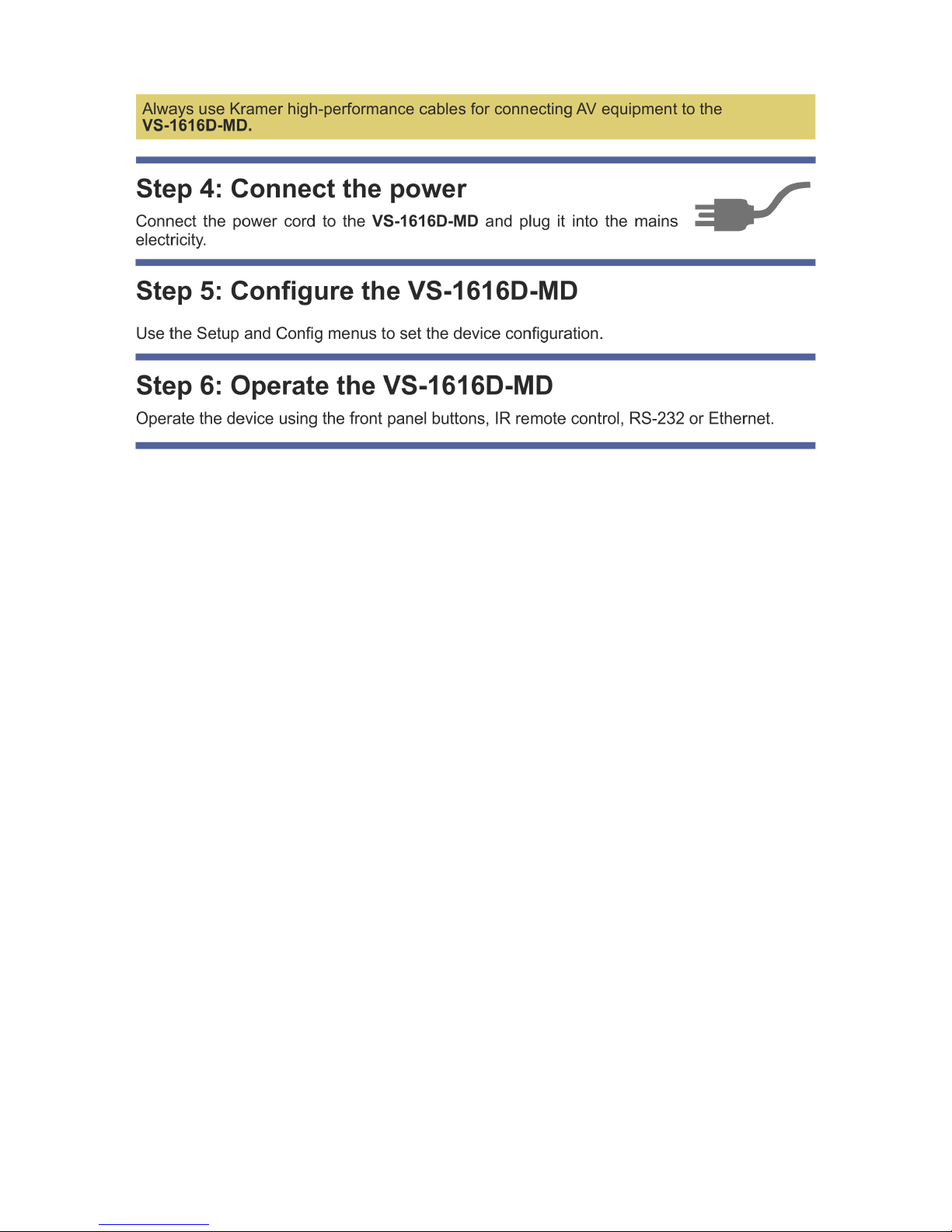
Page 4

VS-1616D-MD – Contents
i
Contents
1 Introduction 1
2 Getting Started 3
2.1 Achieving the Best Performance 3
2.2 Safety Instructions 4
2.3 Safety Instructions (Laser) 4
2.4 Compliance with Leakage Current Requirements 4
2.5 Recycling Kramer Products 5
2.6 Medical Electrical Equipment (IEC 60601-1) 5
3 Overview 6
3.1 About Fast Switching 7
3.2 About HDBaseT™ Technology 8
3.3 About the Power Connect™ Feature 8
4 Defining the VS-1616D-MD 16x16 Digital Matrix Switcher 9
5 Installing in a Rack 14
6 Connecting the VS-1616D-MD 15
6.1 Card Limitations 16
6.2 Port Numbering 17
6.3 Serial Data on DGKat Plus RS-232 Cards 19
6.4 Connecting to the VS-1616D-MD via RS-232 20
6.5 Connecting to the VS-1616D-MD via Ethernet 20
7 Operating Your Video Matrix Switcher 24
7.1 Startup Display 24
7.2 Using the Selector Buttons 25
7.3 Confirming Actions 26
7.4 Switching Actions 27
7.5 Locking the Front Panel Buttons 30
8 Using the Configuration Menus 31
8.1 Using the Setup Menu 32
8.2 Using the Config Menu 37
9 Configuring the Number of Installed Input and Output Ports 61
10 Installing and Using the Test Module to Troubleshoot Video Problems 62
10.1 Installing the Test Module 62
10.2 Setting the Resolution of the Generated Video 63
10.3 Setting the Pattern of the Generated Video 64
10.4 Using the Test Module to Troubleshoot Video Problems 64
11 Hardware Installation Instructions 67
11.1 I/O Card Installation 67
12 Upgrading the VS-1616D-MD Firmware 70
13 Technical Specifications 71
14 Default Communication Parameters 74
15 Label Information 75
16 Factory Default EDID 76
16.1 DVI Input Card 76
16.2 HDCP Input Card 77
16.3 HDMI Input Card 79
16.4 HDMI plus Audio Input Card 81
Page 5

ii
VS-1616D-MD - Introduction
16.5 DVI Dual Channel Input Card 83
16.6 DGKat Input Card 85
16.7 HDBaseT Input Card 87
16.8 VGA Input Card 89
17 Communication Protocol 3000 91
17.1 Kramer Protocol 3000 Syntax 91
17.2 Table of Protocol 3000 Commands 94
18 Communication Protocol 2000 95
Figures
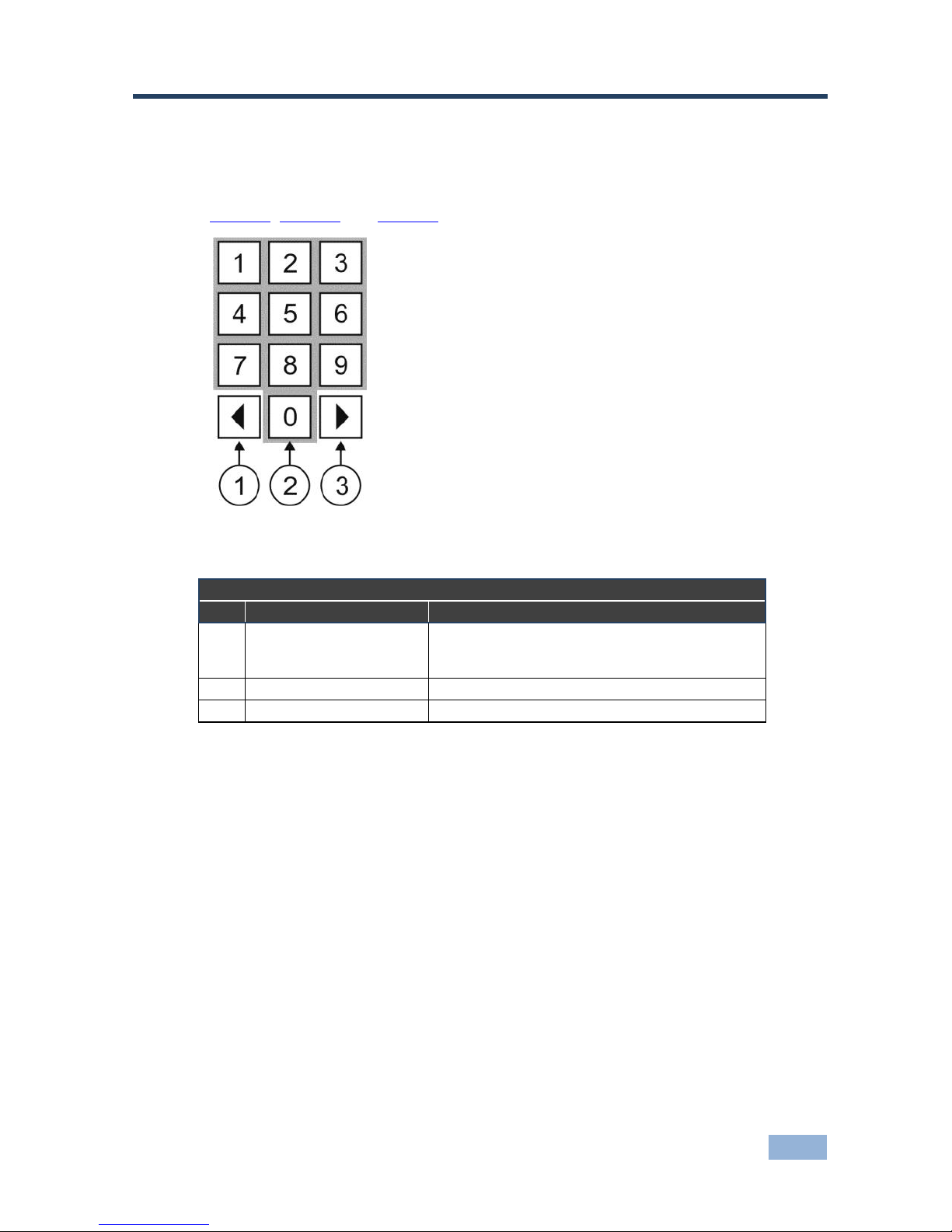
Figure 1: VS-1616D-MD Front Panel Numeric Keypad 9
Figure 2: VS-1616D-MD 16x16 Digital Matrix Switcher Front Panel 10
Figure 3: VS-1616D-MD 16x16 Digital Matrix Switcher Rear Panel 12
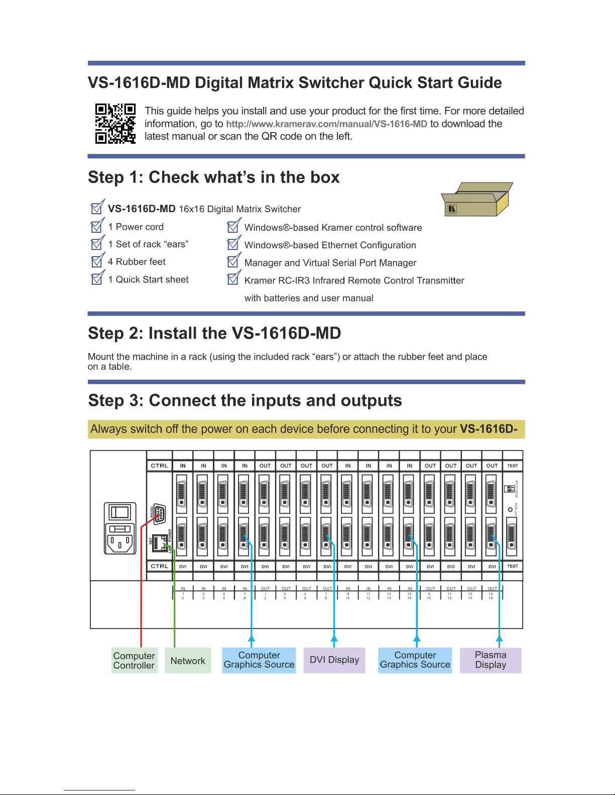
Figure 4: Connecting the VS-1616D-MD 16x16 Digital Matrix Switcher 15
Figure 5: Sample Port Numbering 17
Figure 6: EDID Numbering Assignment 19
Figure 7: DGKat Card Serial Data Transmission 19
Figure 8: Local Area Connection Properties Window 21
Figure 9: Internet Protocol Version 4 Properties Window 22
Figure 10: Internet Protocol Version 6 Properties Window 22
Figure 11: Internet Protocol Properties Window 23
Figure 12: Default Startup Status Display Sequence 24
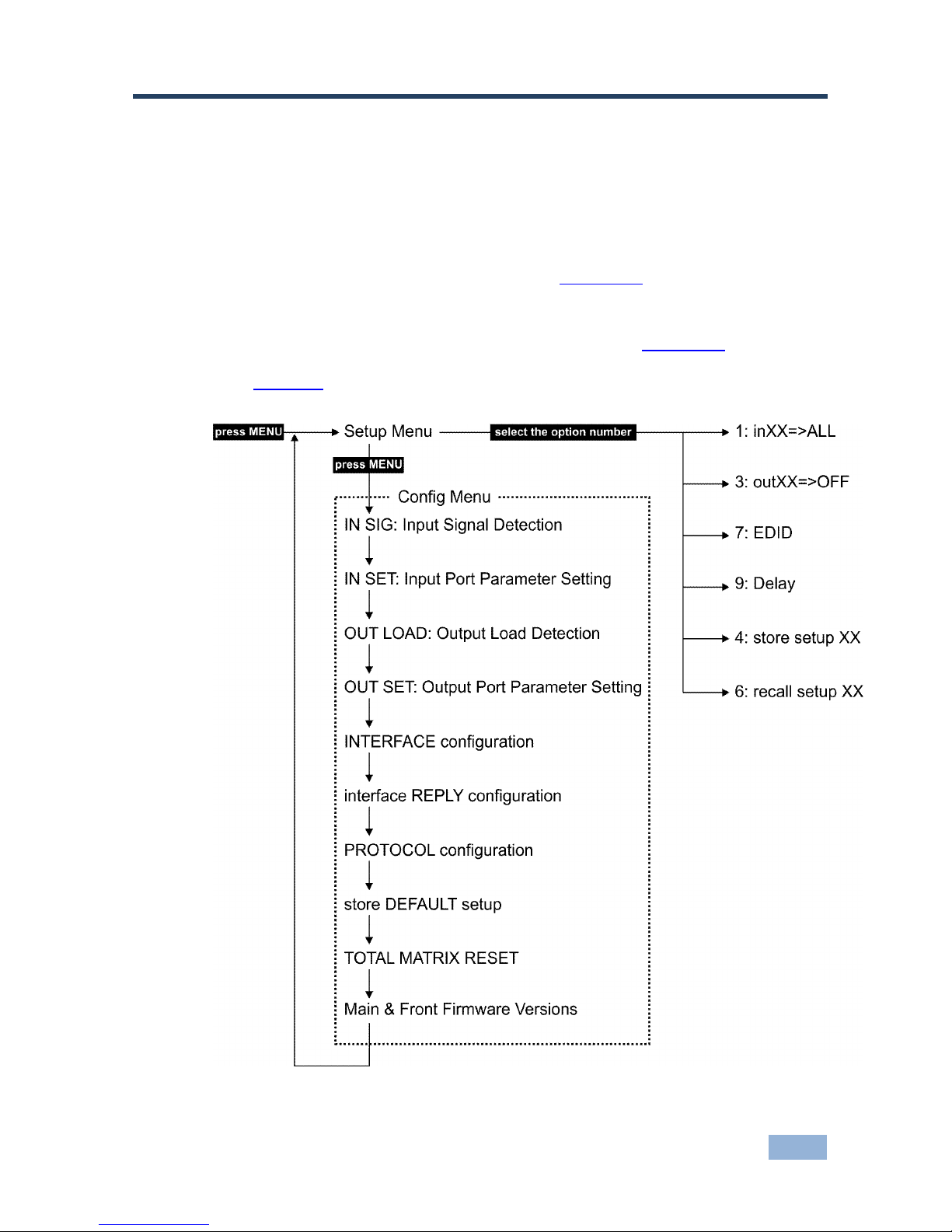
Figure 13: Menu Tree 31
Figure 14: Resolution DIP-switch 63
Figure 15: Signal Paths for Isolating Problems 64
Figure 16: Inserting the Card into a Slot 67
Figure 17: Card Handles 68
Figure 18: Device Label 75
Page 6

VS-1616D-MD - Introduction
1
1 Introduction
Welcome to Kramer Electronics! Since 1981, Kramer Electronics has been
providing a world of unique, creative, and affordable solutions to the vast range of
problems that confront video, audio, presentation, and broadcasting professionals
on a daily basis. In recent years, we have redesigned and upgraded most of our
line, making the best even better!
Our 1,000-plus different models now appear in 14 groups that are clearly defined
by function: GROUP 1: Distribution Amplifiers; GROUP 2: Switchers and Routers;
GROUP 3: Control Systems; GROUP 4: Format/Standards Converters; GROUP 5:
Range Extenders and Repeaters; GROUP 6: Specialty AV Products; GROUP 7:
Scan Converters and Scalers; GROUP 8: Cables and Connectors; GROUP 9:
Room Connectivity; GROUP 10: Accessories and Rack Adapters and GROUP 11:
Sierra Video Products; GROUP 12: Digital Signage; and GROUP 13: Audio, and
GROUP 14: Collaboration.
Congratulations on purchasing your Kramer VS-1616D-MD 16x16 Digital Matrix
Switcher which is ideal for the following typical applications:
Professional display systems requiring video signal routing
Broadcast, presentation and production facilities, as well as monitoring in
large duplication systems
Rental/staging applications
Note: Throughout this user manual the chassis configuration is shown with 16 DVI
inputs and 16 DVI outputs as a representation only. The following cards are
available and may be mixed in the same chassis:
Analog audio plus digital audio
DGKat plus RS-232 (HDCP)
DisplayPort plus analog audio
DVI
DVI (HDCP)
DVI dual link
Page 7

2
VS-1616D-MD - Introduction
HDMI (HDCP)
HDMI (over 4LC fiber optic cable) with 610 module
HDMI (over SC fiber optic cable) with 670 module (HDCP), see note below
HDMI (over HDBaseT) plus IR, RS-232 and Ethernet (HDCP)
HDMI plus analog audio (HDCP)
HDMI UHD plus analog audio (HDCP)
HDMI plus digital audio (HDCP)
HDMI output scaler (HDCP)
HDMI UHD (over HDBaseT 70m) plus IR and RS-232 (HDCP)
SDI plus analog audio
Test card plus analog audio embedding/de-embedding
VGA
VGA plus analog audio
Note: The HDMI over fiber optic with 670 module cards are fully compatible with
the Kramer 670T/670R and 671T/671R HDMI/DVI transmitters and receivers for
non-HDCP content.
Page 8
VS-1616D-MD - Getting Started
3
2 Getting Started
The following symbols are used in this manual:
Warning:
Indicates a possible hazard to life or serious injury to
persons
Caution:
Recommended procedure which if not followed may
result in damage to the equipment or injury to persons
We recommend that you:
Unpack the equipment carefully and save the original box and packaging
materials for possible future shipment
Review the contents of this user manual
Go to http://www.kramerav.com/downloads/VS-1616D-MD to check for up-
to-date user manuals, application programs, and to check if firmware
upgrades are available (where appropriate).
2.1 Achieving the Best Performance
To achieve the best performance:
Use only good quality connection cables to avoid interference, deterioration
in signal quality due to poor matching, and elevated noise levels (often
associated with low quality cables)
Do not secure the cables in tight bundles or roll the slack into tight coils
Avoid interference from neighboring electrical appliances that may adversely
influence signal quality
Position your Kramer VS-1616D-MD away from moisture, excessive sunlight
and dust
This equipment is to be used only inside a building. It may be connected
only to other equipment that is installed inside a building.
Page 9

4
VS-1616D-MD - Getting Started
2.2 Safety Instructions
Warning:
No operator serviceable parts inside the unit
Warning:
Use only the Kramer Electronics input power wall
adapter that is provided with the unit.
Warning:
Disconnect the power and unplug the unit from the wall
before installing
Warning:
To avoid risk of electric shock, this equipment must only
be connected to a supply mains with protective earth
Warning:
No modification of this equipment is allowed
Warning:
Do not install this equipment in a patient environment
2.3 Safety Instructions (Laser)
Warning:
Class 1 laser product
Invisible laser radiation present
Avoid long-term viewing of laser
Avoid the use of magnifying viewing aids or instruments
(such as binoculars, telescopes, microscopes and
magnifying lenses, but not spectacles or contact lenses)
Avoid placing optical devices in the emitted beam that
could cause the concentration of the laser radiation to be
increased
2.4 Compliance with Leakage Current Requirements
To ensure compliance with leakage current requirements in medical systems, the
following connections between input and output connectors are allowed:
Non-optical communication—Medical to medical, non-medical to
non-medical, where:
Medical—Device certified according to IEC 60601-1
Non-medical—Device certified according to other standard(s)
Optical communication—No restrictions
Page 10

VS-1616D-MD - Getting Started
5
2.5 Recycling Kramer Products
The Waste Electrical and Electronic Equipment (WEEE) Directive 2002/96/EC
aims to reduce the amount of WEEE sent for disposal to landfill or incineration by
requiring it to be collected and recycled. To comply with the WEEE Directive,
Kramer Electronics has made arrangements with the European Advanced
Recycling Network (EARN) and will cover any costs of treatment, recycling and
recovery of waste Kramer Electronics branded equipment on arrival at the EARN
facility. For details of Kramer’s recycling arrangements in your particular country
go to our recycling pages at http://www.kramerelectronics.com/support/recycling/.
2.6 Medical Electrical Equipment (IEC 60601-1)
In the modern medical environment remote access is essential, for example, to
transfer clinical data between doctors and to train to medical students. The
VS-1616D-MD is certified according to the IEC 60601-1, Clause 2.1.3, Medical
Electrical Equipment, Part 1: General Requirements for EMC standard which is
required when accessory devices are used at locations where medical personnel
and patients are present.
The VS-1616D-MD constitutes an optional component that can be considered
necessary and suitable as part of medical equipment or for use as part of a
medical system to provide real time simultaneous video feeds to those present at
the local medical environment and at remote locations. In this environment, the
product can be added to the system ONLY if the connecting equipment has been
evaluated and meets the IEC 60601-1 safety standards. Note, that when attaching
accessory devices to a digital or analog interface, they must comply with the IEC
standard for which they are used: Safety Standard (IEC 60601-1), Information
Technology equipment (IEC 60950-1 (2ed)).
Page 11

6
VS-1616D-MD - Overview
3 Overview
The Kramer VS-1616D-MD is a high performance matrix switcher chassis that
supports up to 16 x 16 ports. It features a very high bandwidth of up to 3.2Gbps
(for the chassis only, effective bandwidth of the system depends on the I/O cards)
that ensures transparent performance even in the most critical applications. The
cards re-clock and equalize the signals and the chassis can route any or all inputs
to any or all outputs simultaneously.
For maximum bandwidth supported by each type of card see the Technical
Specifications in Section 13.
The VS-1616D-MD is highly configurable–you can add or remove inputs and
outputs independently in groups of four and mix different types of input/output
cards in the same chassis up to 16 x 16. For example, you can configure a device
as a 4 x 12 or a 16 x 8 matrix switcher to exactly suit your needs.
The VS-1616D-MD features:
Full 16 x 16 non-blocking matrix array to switch any of the 16 input digital
signals to any or all outputs (with limitations, see Section 6)
Kramer Core™—flexible infrastructure conversion. Copper, fiber or Twisted
Pair, all can be used at the same time according to input/output module
selection. The matrix receives signals from compatible Kramer transmitters,
automatically converts between available infrastructure options and sends
the signals to compatible Kramer receivers
Fast switching on outputs to reduce or remove switching delay
A default EDID (Extended Display Identification Data) for each input
EDID Capture – Copies and stores the EDID from a display device
EDID PassThru – Passes EDID/HDCP signals from source to display
Non-volatile EDID storage
Page 12

VS-1616D-MD - Overview
7
Kramer Core™—flexible infrastructure conversion. Copper, fiber or Twisted
Pair, all can be used at the same time according to input/output module
selection. The matrix receives signals from compatible Kramer transmitters,
automatically converts between available infrastructure options and sends
the signals to compatible Kramer receivers
Equalization and re-clocking on all card types
Easy access to 59 preset memory locations for quick access to user-defined
setups
The Kramer 2000 Protocol for serial control
A lock function to prevent tampering with the front panel
A 40 character by 2 line LCD that shows the operational status or the
configuration menu
You can operate the VS-1616D-MD via the front panel buttons or remotely via:
RS-232 serial commands transmitted by a touch screen system, PC or other
serial controller
Ethernet over a LAN
The infrared remote control transmitter
Kramer K-Router Plus software application
The VS-1616D-MD is a sophisticated device but has been designed to be as
simple as possible to operate. Due to space limitations on the front panel a keypad
substitutes for 64 individual input/output selector buttons. For details of how to
route inputs to outputs, see Section 6. The VS-1616D-MD is housed in a 19" rack-
mountable enclosure.
3.1 About Fast Switching
Older display devices required a longer time between the loss of one digital signal
and the introduction of another, as well as a physical disconnection of the
interconnecting cable in order to be able to detect and adjust to the new video
attributes and parameters. Normal switching, therefore, introduced a 5V signal
disconnection along with a delay in switching. Many newer display devices
however, are now capable of accepting “on-the-fly” switching.
Page 13

8
VS-1616D-MD - Overview
Depending on the display device in use, the VS-1616D-MD allows for fast
switching (minor reset and the connection kept alive) and extra fast switching (no
reset and the connection kept alive), see Section 8.2.4. Using the fast and extra
fast switching modes allows for fraction-of-a-second switching times when using
high performance display devices or when using a scaler on the video output.
3.2 About HDBaseT™ Technology
HDBaseT™ is an advanced all-in-one connectivity technology (supported by the
HDBaseT Alliance). It is particularly suitable in the consumer home environment
as a digital home networking alternative where it enables you to replace numerous
cables and connectors by a single LAN cable used to transmit, for example,
uncompressed full high definition video, audio, IR, as well as various control
signals.
The HDBaseT products described in this user manual are HDBaseT
certified.
3.3 About the Power Connect™ Feature
The Power Connect™ feature means that the VS-1616D-MD can supply power
over the TP cable to compatible DGKat devices (for example, the TP-573 or
TP-574) when the devices are within 90m (270ft) of each other. The Power
Connect™ feature applies as long as the cable can carry power and the distance
does not exceed 90m on standard TP cable. For longer distances, use heavier
gauge cable (TP cable is still suitable for the video/audio transmission, but not for
feeding power at these distances).
Page 14
VS-1616D-MD - Defining the VS-1616D-MD 16x16 Digital Matrix Switcher
9
4 Defining the VS-1616D-MD 16x16 Digital
Matrix Switcher
Figure 1, Figure 2 and Figure 3 define the VS-1616D-MD.
Figure 1: VS-1616D-MD Front Panel Numeric Keypad
Front Panel Numeric Keypad Labels
#
Feature
Function
1
◄ (Backwards)
Press to shift the sliding window to the right (The
LCD display is large enough to show only 13
cross-points out of a total of 32)
2
1, 2, 3, 4, 5, 6, 7, 8, 9, 0
Numeric keypad, 1 to 0
3
► (Forward)
Press to shift the sliding window to the left
Page 15
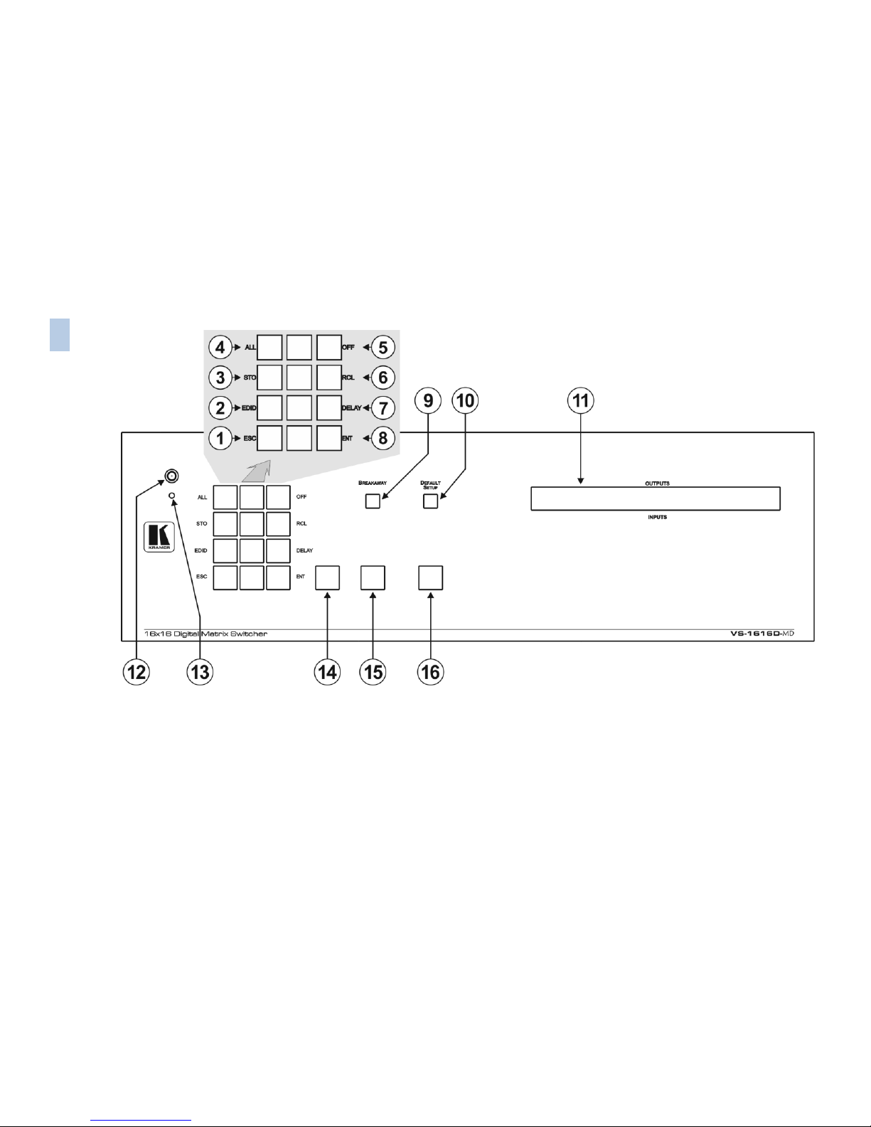
Figure 2: VS-1616D-MD 16x16 Digital Matrix Switcher Front Panel
10
VS-1616D-MD – Defining the VS-1616D-MD 16x16 Digital Matrix Switcher
Page 16
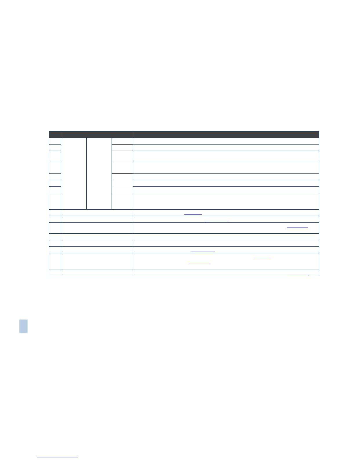
VS-1616D-MD -
11
VS-1616D-MD – Defining the VS-1616D-MD 16x16 Digital Matrix Switcher
11
#
Feature
Function
1
Doublefunction
Selector
Button
Area
Menu
Button
Functions
ESC
Press to exit the current operation
2
EDID
Press to assign EDID channels
3
STO
Press to store the current setup in a preset. After pressing the MENU button, this button lights
and is enabled
4
ALL
Press to connect an input to all outputs. After pressing the MENU button, this button lights and is
enabled
5
OFF
Press to turn off an output. After pressing the MENU button, this button lights and is enabled
6
RCL
Press to recall a preset. After pressing the MENU button, this button lights and is enabled
7
DELAY
Press to set the delay between confirming an action and the execution of the action
8
ENT
Press to complete the input-output setup when using a one-digit number instead of two digits.
Press to enter the options in a setup menu. (For example, to enter input 5, you can either press
05 or 5, ENT)
9
BREAKAWAY Button
Press to exit a Menu (see Section 8)
10
DEFAULT SETUP Button
Press to recall the default setup (see Section 7.4.5)
11
OUTPUTS/INPUTS LCD Display
Displays the outputs (upper row) switched to the selected inputs (lower row), (see Section 7.1).
Displays user interface messages and menus
12
IR Receiver
Infrared remote control sensor
13
IR LED
Lights yellow when receiving commands from the IR remote control transmitter
14
TAKE Button
Press to confirm actions (see Section 7.3.2)
15
MENU Button
Press once to enable the ALL, OFF STO and RCL buttons (see Section 8). Press again to enter
the configuration menu (see Section 8.2).
When in a Menu, press to cycle through the menu items
16
LOCK Button
Press and hold for approximately 2 sec to lock/unlock the front panel buttons (see Section 7.5)
Page 17
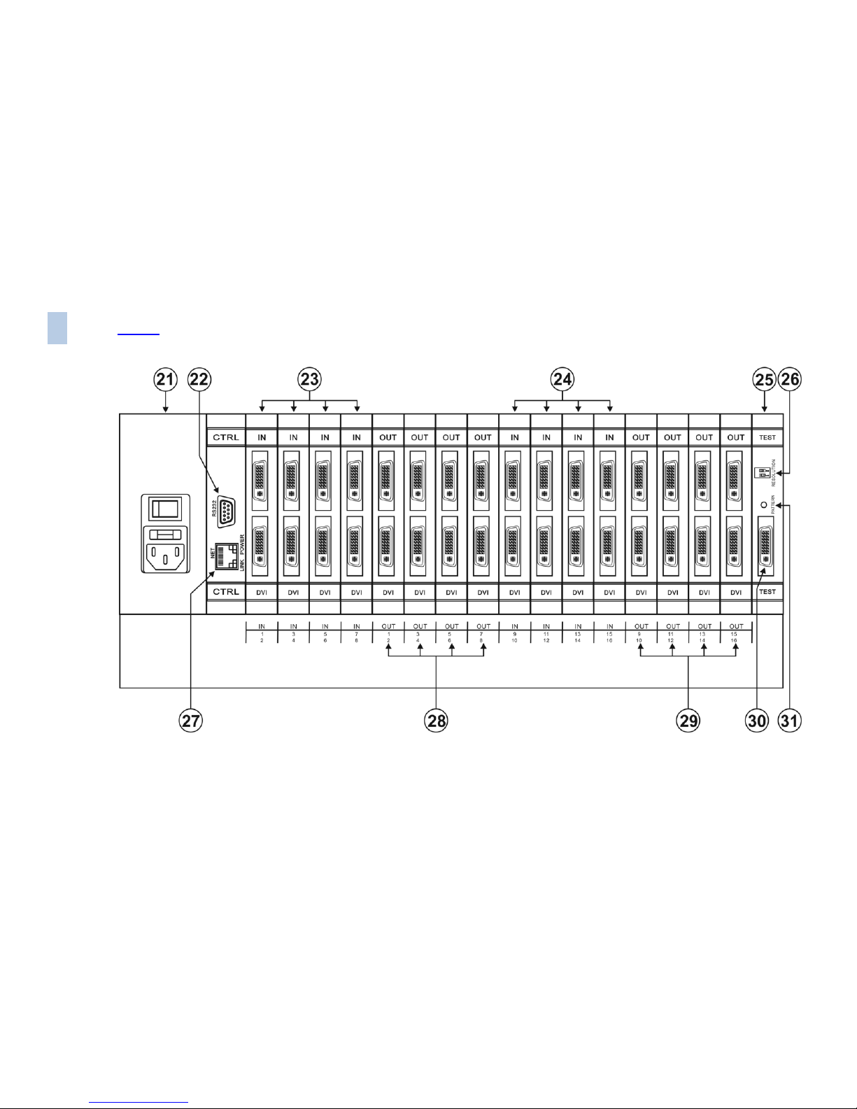
Figure 3 shows DVI cards installed as an example.
Figure 3: VS-1616D-MD 16x16 Digital Matrix Switcher Rear Panel
12
VS-1616D-MD – Defining the VS-1616D-MD 16x16 Digital Matrix Switcher
Page 18
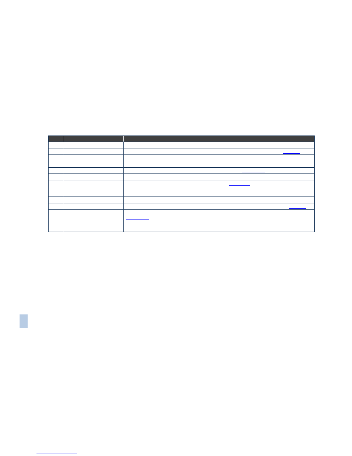
VS-1616D-MD -
13
VS-1616D-MD – Defining the VS-1616D-MD 16x16 Digital Matrix Switcher
13
#
Feature
Function
21
AC Mains Power Module
Fuse holder and power cord socket. Connect to the AC mains supply
22
IN 1~16 Connectors
Connect to the relevant video sources, depending on the cards installed (1 to 16, see Section 6)
23
IN 17~32 Connectors
Connect to the relevant video sources, depending on the cards installed (17 to 32, see Section 6)
24
TEST Module
Signal generator module for testing video outputs (see Section 10)
25
RESOLUTION DIP-switches
Set the resolution for video generated by the Test module (see Section 10.2)
26
RS-232 9-pin D-sub Port
Connects to the remote operation PC or remote controller (see Section 6.2)
27
NET Ethernet RJ-45
Connector
Connect to a PC or controller via the Ethernet LAN (see Section 6.5).
The LINK LED flashes when communication is active. The POWER LED lights when the interface
receives power
28
OUT 1~16 Connectors
Connect to the relevant video acceptors, depending on the cards installed (1 to 16, see Section 6)
29
OUT 17~32 Connectors
Connect to the relevant video acceptors, depending on the cards installed (17 to 32, see Section 6)
30
PATTERN Button
Press the button repeatedly to change the video pattern generated by the Test module (see
Section 10.3)
31
Test Module Output
Connector
Connect to one of the relevant video inputs to aid in troubleshooting (see Section 10.4)
Page 19
14
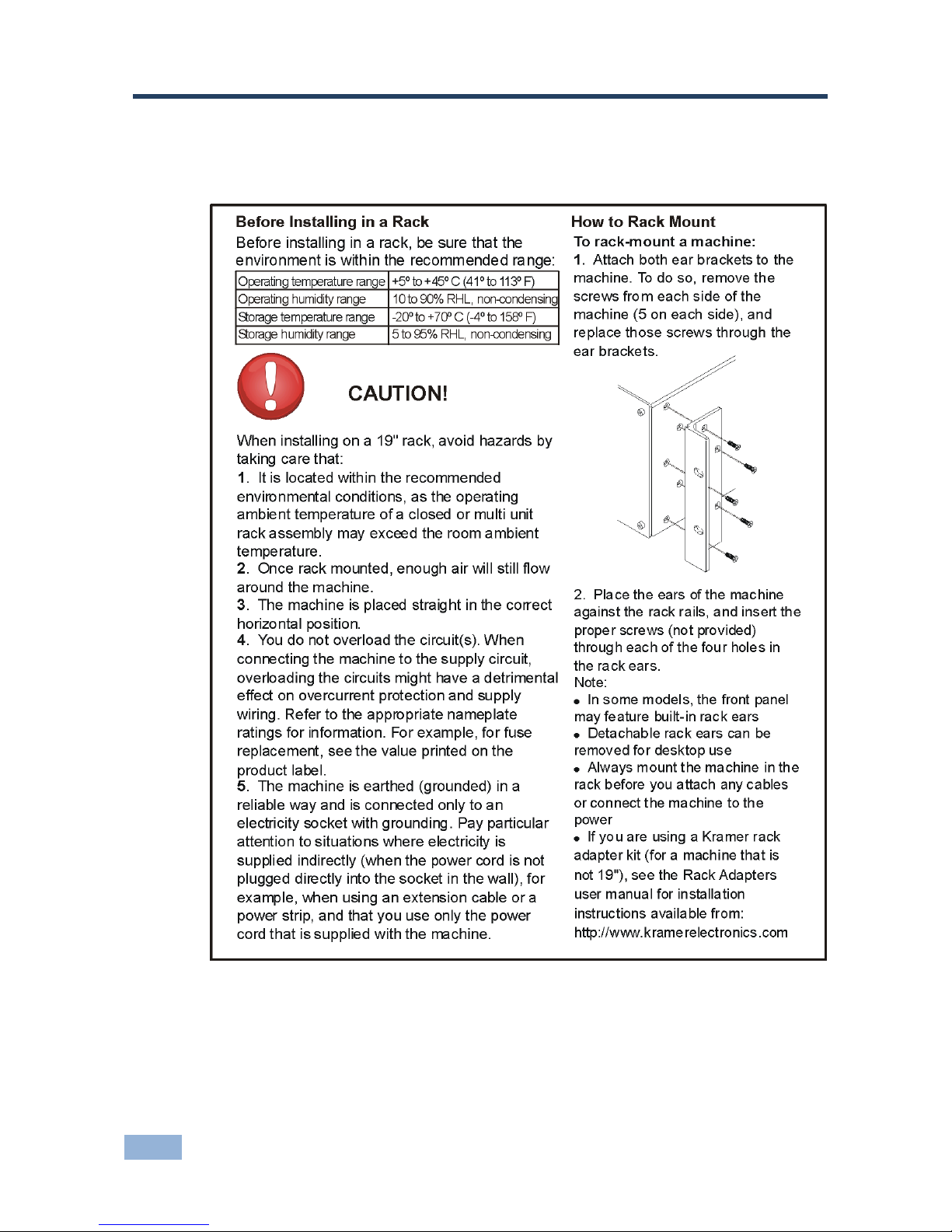
VS-1616D-MD - Installing in a Rack
5 Installing in a Rack
This section provides instructions for rack mounting the unit.
Page 20
VS-1616D-MD - Connecting the VS-1616D-MD
15
6 Connecting the VS-1616D-MD
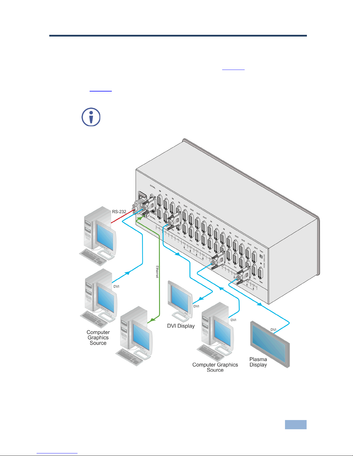
The configuration of DVI input/output cards shown in Figure 4 is a sample
representation and different I/O cards may be mixed as required (for limitations,
see page 17). Exactly the same principles apply to installations using other card
types.
Always switch off the power to all devices before connecting them to
your VS-1616D-MD. After connecting your VS-1616D-MD, connect its
power and then switch on the power to each device.
Figure 4: Connecting the VS-1616D-MD 16x16 Digital Matrix Switcher
Page 21

16
VS-1616D-MD - Connecting the VS-1616D-MD
Warning:
To avoid risk of electric shock, this equipment must only
be connected to a supply mains with protective earth
To install the VS-1616D-MD as illustrated in the example in Figure 4:
1. Connect up to 16 DVI video sources (for example, computer graphics
sources).
In this example only two inputs and two outputs are connected.
2. Connect up to 16 DVI video acceptors, (for example, a plasma display and a
DVI LCD display).
3. If required, connect a PC or remote controller to the RS-232 port (see
Section 6.2) and/or the Ethernet port (see Section 6.5).
4. Connect the power cord.
We recommend that you use only the power cord that is supplied with the device (not
shown in Figure 4).
5. If necessary, review and set the system configuration using the Menu (see
Section 8).
Note: Given an input signal that is HDCP encoded, the VS-1616D-MD outputs a
signal only if the output port supports HDCP, (for example, HDMI input and DVI
with HDCP output).
6.1 Card Limitations
6.1.1 HDBT Input Cards
The chassis is limited to a maximum of three HDBT input cards due to thermal
constraints. When installing these input cards they must occupy input slots IN 5~8,
IN 9~12, and IN 13~16 (in that order, as needed). Input slot IN 1~4 must be left
unpopulated and sealed with a blank cover. Contact Kramer Electronics for more
information on installing a fourth HDBT input card.
There is no limit to the number or type of output cards that can be installed.
Page 22
VS-1616D-MD - Connecting the VS-1616D-MD
17
6.1.2 HDBT7 Input Cards
When using the HDBT7 Input card to support 4K video resolution, the chassis is
limited to one input card.
6.2 Port Numbering
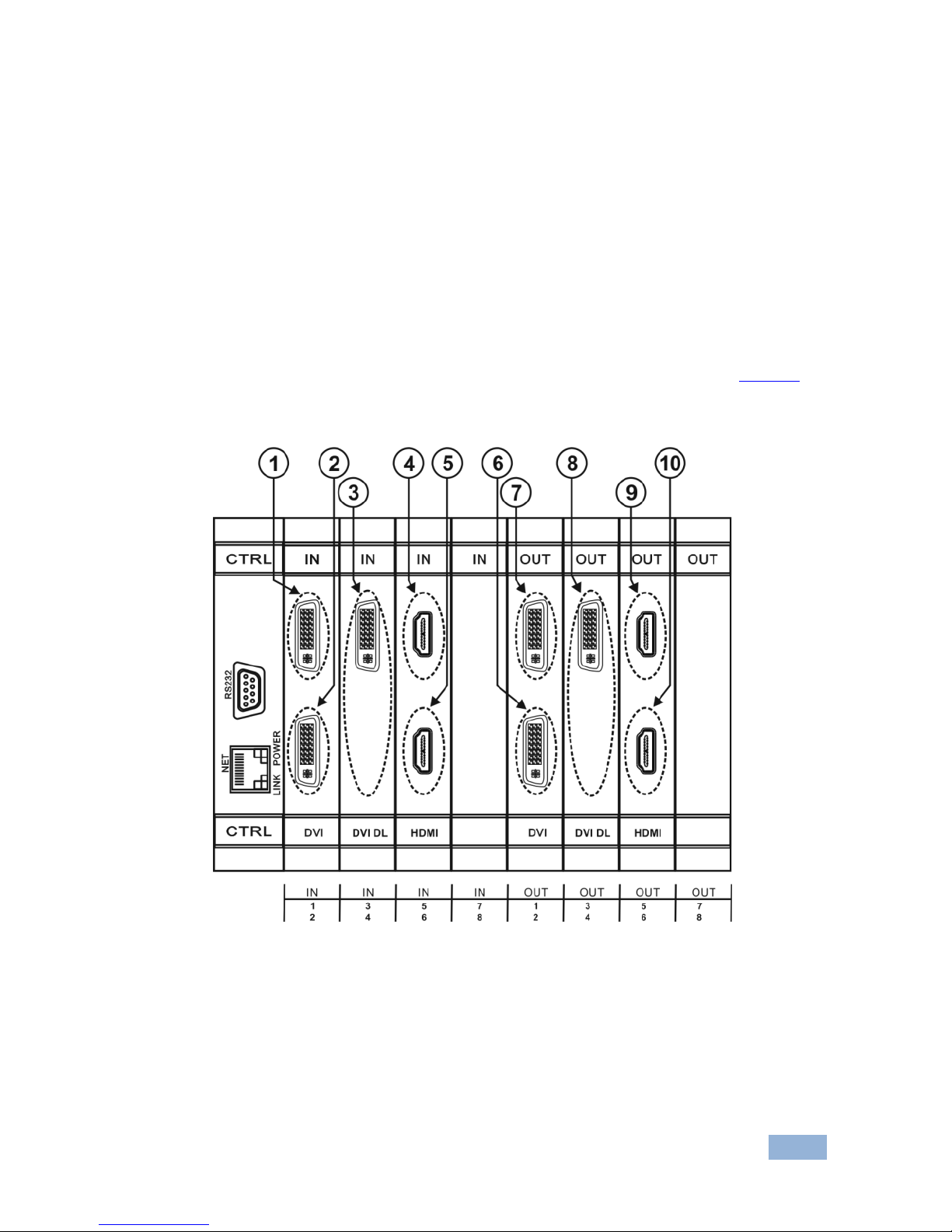
On all cards apart from the DVI dual link cards there are four physical ports. The
numbering of ports is sequential from top to bottom and left to right. Each DVI dual
link card provides two physical ports which causes the loss of two numbers in the
numbering sequence of that card only. A sample numbering is shown in Figure 5.
Figure 5: Sample Port Numbering
Page 23

18
VS-1616D-MD - Connecting the VS-1616D-MD
Diagram #
Actual Port
Number
Diagram #
Actual Port
Number
1
IN 1 6 OUT 2
2
IN 2 7 OUT 1
3
IN 3 8 OUT 3
4
IN 5 9 OUT 5
5
IN 6
10
OUT 6
Note: There is no IN 4 or OUT 4 because these slots contain DVI dual link cards.
On all cards apart from the DVI dual link cards, there are two physical ports on
each card and numbering of ports is sequential from top to bottom and left to right.
Each DVI dual link card provides one physical port which causes the loss of one
number in the numbering sequence of that card only. A sample numbering is
shown in Figure 5 and described in the table that follows it.
6.2.1 EDID Numbering Examples
The following table is based on the port numbering shown in Figure 5 and lists
requested switching configurations and their results.
EDID Request
EDID Sent
From OUT 4
Blank (256 bytes of 0xFF)
From IN 8
None (error message displayed)
Note: AV data flow is: source > VS-1616D-MD > display. EDID information flow
is: display > VS-1616D-MD > source, which means that the EDID input is the
display side and the EDID output is the AV source side. This is the reverse of the
AV data flow direction.
When assigning EDIDs, note that the top row of the LCD display labeled
OUTPUTS relates to the ports connected to the sources (AV inputs), and the
bottom row of the LCD display labeled INPUTS relates to the ports connected to
displays (AV outputs).
In Figure 6, the EDID from EDID input 8 (VS-1616D-MD Output port 8) has been
assigned to all EDID outputs (VS-1616D-MD Input ports).
Page 24
VS-1616D-MD - Connecting the VS-1616D-MD
19
Figure 6: EDID Numbering Assignment
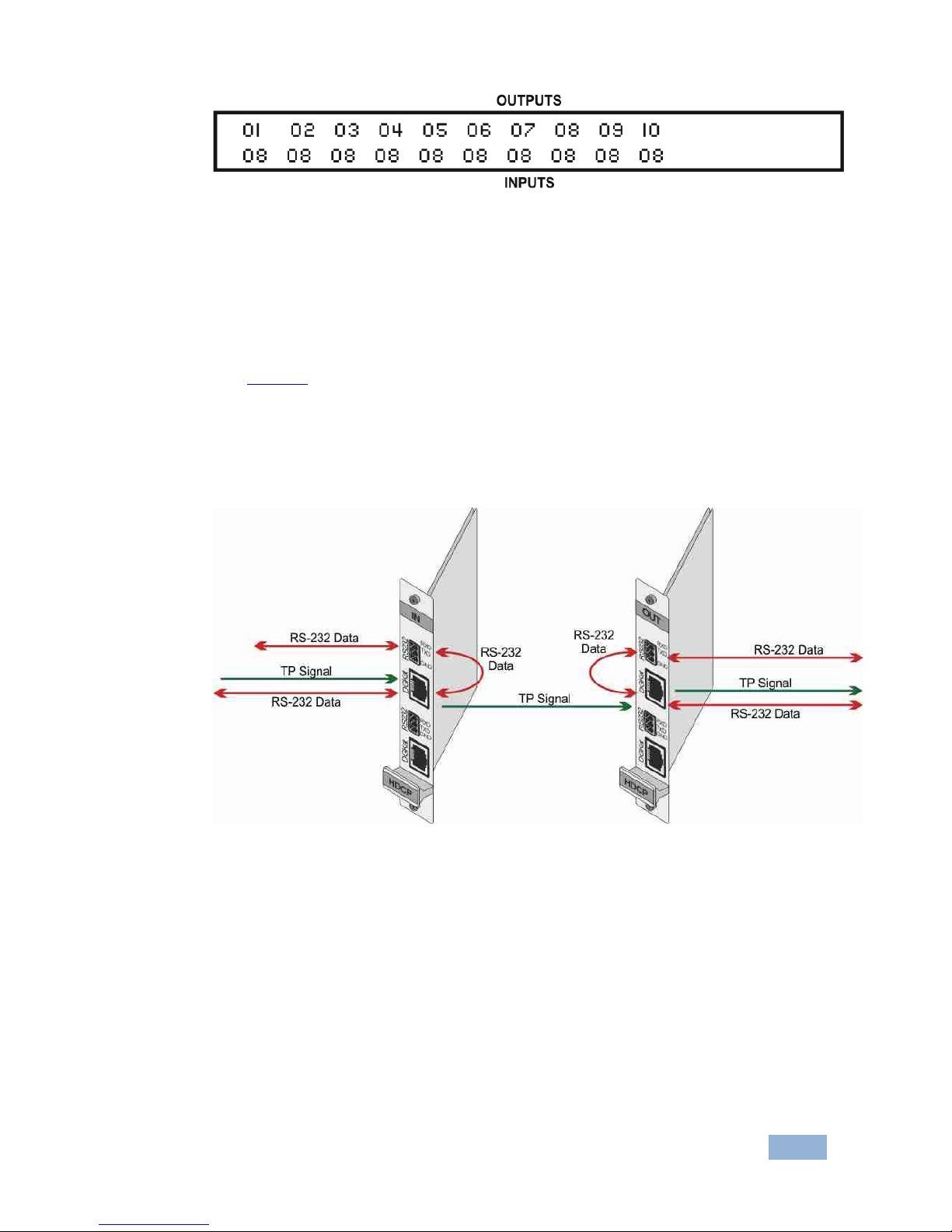
6.3 Serial Data on DGKat Plus RS-232 Cards
Serial data present on the RS-232 port of a DGKat input card is not transmitted via
the switcher. This data is transmitted over the TP cable of the same input card
(see Figure 7).
Serial data present on the RS-232 port of a DGKat output card are not transmitted
via the switcher. This data are transmitted over the TP cable of the same output
card.
Figure 7: DGKat Card Serial Data Transmission
Page 25

20
VS-1616D-MD - Connecting the VS-1616D-MD
6.4 Connecting to the VS-1616D-MD via RS-232
You can connect to the VS-1616D-MD via an RS-232 connection using, for
example, a PC. Note that a null-modem adapter/connection is not required.
Note: Some early devices require a null modem.
To connect to the VS-1616D-MD via RS-232:
Connect the RS-232 9-pin D-sub rear panel port on the VS-1616D-MD unit
via a 9-wire straight cable (only pin 2 to pin 2, pin 3 to pin 3, and pin 5 to pin
5 need to be connected) to the RS-232 9-pin D-sub port on your PC
6.5 Connecting to the VS-1616D-MD via Ethernet
You can connect to the VS-1616D-MD via Ethernet using either of the following
methods:
Directly to the PC using a crossover cable (see Section 6.5.1)
Via a network hub, switch, or router, using a straight-through cable (see
Section 6.5.2)
Note: If you want to connect via a router and your IT system is based on IPv6,
speak to your IT department for specific installation instructions.
6.5.1 Connecting the Ethernet Port Directly to a PC
You can connect the Ethernet port of the VS-1616D-MD directly to the Ethernet
port on your PC using a crossover cable with RJ-45 connectors.
This type of connection is recommended for identifying the
VS-1616D-MD with the factory configured default IP address.
After connecting the VS-1616D-MD to the Ethernet port, configure your PC as
follows:
1. Click Start > Control Panel > Network and Sharing Center.
2. Click Change Adapter Settings.
Page 26
VS-1616D-MD - Connecting the VS-1616D-MD
21
3. Highlight the network adapter you want to use to connect to the device and
click Change settings of this connection.
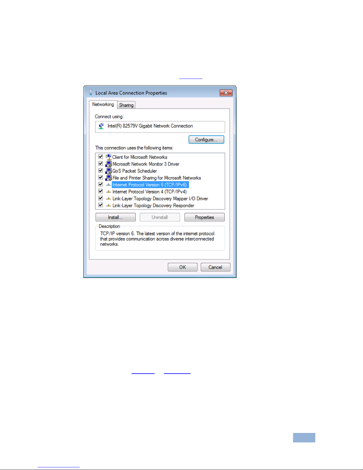
The Local Area Connection Properties window for the selected network
adapter appears as shown in Figure 8.
Figure 8: Local Area Connection Properties Window
4. Highlight either Internet Protocol Version 6 (TCP/IPv6) or Internet
Protocol Version 4 (TCP/IPv4) depending on the requirements of your IT
system.
5. Click Properties.
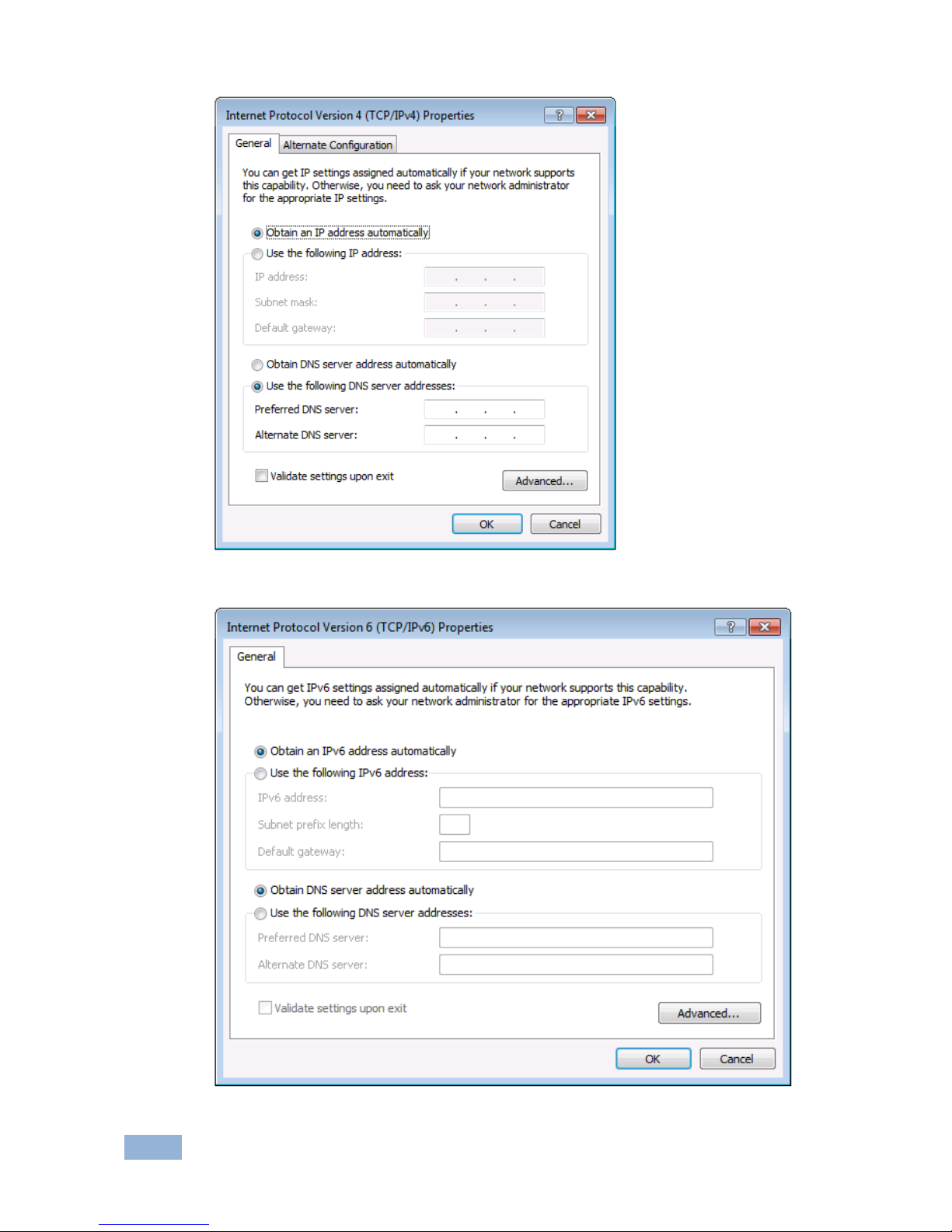
The Internet Protocol Properties window relevant to your IT system appears
as shown in Figure 9 or Figure 10.
Page 27
22
VS-1616D-MD - Connecting the VS-1616D-MD
Figure 9: Internet Protocol Version 4 Properties Window
Figure 10: Internet Protocol Version 6 Properties Window
Page 28
VS-1616D-MD - Connecting the VS-1616D-MD
23
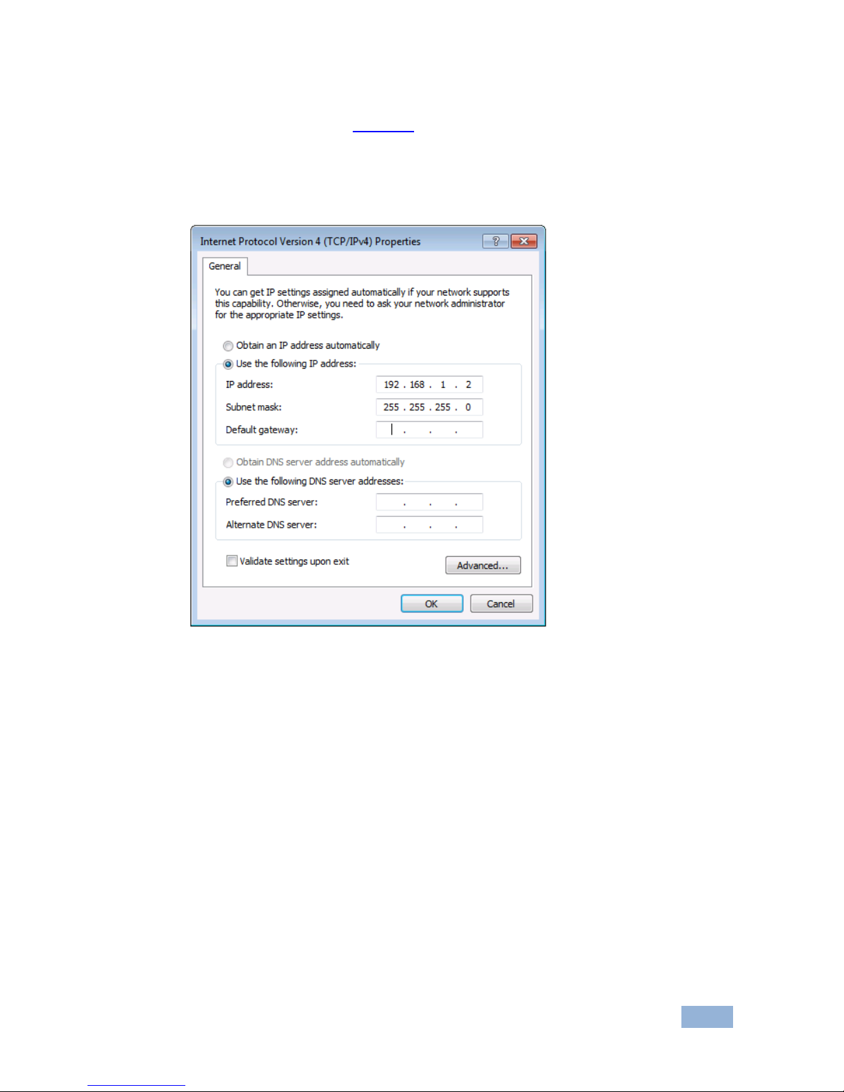
6. Select Use the following IP Address for static IP addressing and fill in the
details as shown in Figure 11.
For TCP/IPv4 you can use any IP address in the range 192.168.1.1 to
192.168.1.255 (excluding 192.168.1.39) that is provided by your IT
department.
Figure 11: Internet Protocol Properties Window
7. Click OK.
8. Click Close.
6.5.2 Connecting the Ethernet Port via a Network Hub or Switch
You can connect the Ethernet port of the VS-1616D-MD to the Ethernet port on a
network hub or using a straight-through cable with RJ-45 connectors.
Page 29
24
VS-1616D-MD - Operating Your Video Matrix Switcher
7 Operating Your Video Matrix Switcher
This section describes:
The startup display (see Section 7.1)
Using the selector buttons (see Section 7.2)
Confirming actions (see Section 7.3)
Switching options (see Section 7.4)
Locking the front panel (see Section 7.5)
7.1 Startup Display
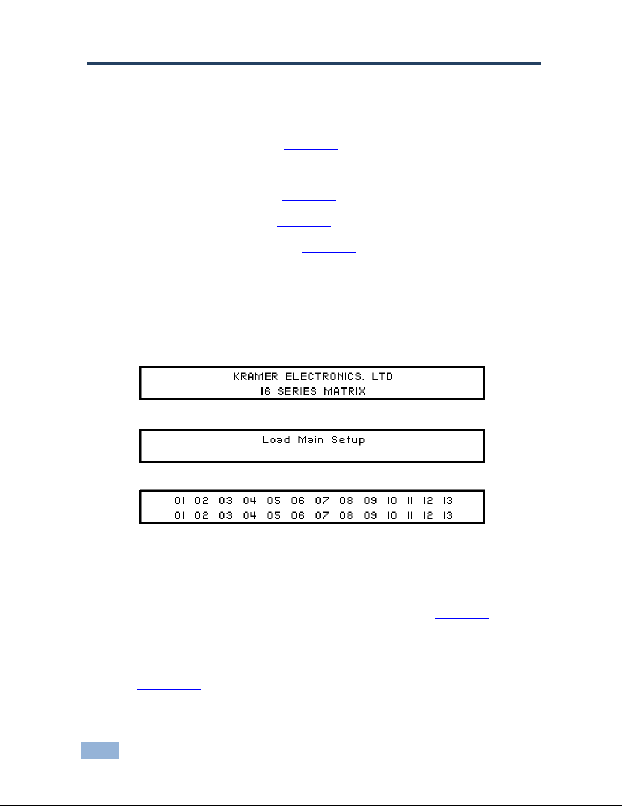
After switching on the power, the LCD display shows the following screens in
sequence.
The text in the LCD Display may vary (according to machine settings)
Figure 12: Default Startup Status Display Sequence
The front panel of the VS-1616D-MD includes a numeric keypad within the
selector buttons area. This keypad lets you enter both the output and input
numbers as well as various numeric configuration values (see Section 7.2).
When the unit is powered-on, the last matrix setup that was used is loaded. Use
either the recall setup (see Section 8.1.6) or default setup recall (see
Section 7.4.5) functions to retrieve other setups.
Records a stored configuration from a preset. For quick retrieval, you can program a default
setup that is commonly used.
Page 30

VS-1616D-MD - Operating Your Video Matrix Switcher
25
7.1.1 Viewing the Display
Figure 12 shows the output-input matrix on the LCD display. The LCD display can
show 13 out of the 32 available matrix combinations at once. To view any of the
matrix combinations use the ◄ or the ► buttons on the front panel to shift the
sliding window to the right or left.
This sliding window functionality is enabled when:
The switcher is in between operations
Waiting for its next operation while all previous operations are complete or cancelled.
Recalling a setup using the ◄ or ► buttons
When entering an output/input combination, the contents of the LCD
display automatically shift to indicate the current status of the
selected output.
7.2 Using the Selector Buttons
For numbers between 1 and 9, the VS-1616D-MD can handle two digit numbers
as well as single digit numbers. When entering a single digit number (for example
5), you can either press 0 followed by 5, or 5 followed by ENT.
Pressing 00 (or 0, ENT) is only relevant for an input selection and is used to
disconnect the currently entered output number from the input.
For example, the following display indicates that inputs 8 and 12 are disconnected
from any output (note that in the second line representing these inputs the display
is blank):
06 07 08 09 10 11 12 13
12 08 10 14 13 06
The ESC button is used to cancel an operation without affecting the current status.
For example, if you enter an incorrect number by mistake, press the ESC button to
cancel the operation.
Note: At any stage, if no button is pressed within approximately 15 seconds, the
automatic timeout causes the VS-1616D-MD to exit the operation and revert to the
output/input display.
Page 31

26
VS-1616D-MD - Operating Your Video Matrix Switcher
7.3 Confirming Actions
You can choose to work in the At Once (default) or the Confirm mode.
For all actions except storing/recalling.
In the At Once mode:
The TAKE button does not light
Pressing an OUT-IN combination implements the switch without further user
confirmation
You save time as execution is immediate and actions require no user
confirmation
No protection is offered to correct an erroneous action
In the Confirm mode:
The TAKE button lights
You enter an action and then confirm it by pressing the TAKE button
Every action requires user confirmation, protecting against erroneous
actions
Execution is postponed until you confirm the action
Failure to press the TAKE button within a few seconds results in the action timing out
automatically
7.3.1 Switching between the At Once and Confirm Modes
To switching between the At Once and Confirm modes:
Note: If the TAKE button is flashing you cannot switch between the At Once and
Confirm modes. A flashing TAKE button indicates that an action is currently
pending confirmation.
1. Press TAKE to switch between the At Once mode and the Confirm mode.
The TAKE button lights and actions now require user confirmation.
Page 32

VS-1616D-MD - Operating Your Video Matrix Switcher
27
2. Press the lit TAKE button to switch from the Confirm mode back to the At
Once mode.
The TAKE button is no longer lit and actions no longer require user
confirmation.
7.3.2 Confirming a Switching Action
Actions only require confirmation when the device is in the Confirm mode.
To confirm a switching action:
1. Using the numeric keypad, enter an output-input combination.
The TAKE button flashes.
2. Press the flashing TAKE button to confirm the action.
The action is confirmed and the TAKE button lights.
7.4 Switching Actions
This section describes how to:
Switch one input to one output (see Section 7.4.1)
Switch several inputs to several outputs (see Section 7.4.2)
Turn off several outputs (see Section 7.4.3)
7.4.1 Switching one Input to one Output
To switch one input to one output:
1. Using the numeric keypad, enter the required output (in this example, 12).
The following is displayed:
06 07 08 09 10 11 12 13
In__ => Out 12
The left-hand side of the display shows a section of the output/input display
automatically sliding the content to include output 12.
Page 33

28
VS-1616D-MD - Operating Your Video Matrix Switcher
2. Using the numeric keypad, enter the required input (in this example, 14):
In the At Once mode, the switching takes place immediately and the
LCD display shows a segment of the input-output status that includes
the switched input and output (for example, 14-12)
In the Confirm mode, the LCD display shows the following:
In 14 => Out 12
Incomplete actions time out after approximately 15 seconds.
In the Confirm mode, press the flashing TAKE button to switch the input
to the output
7.4.2 Switching Several Inputs to Several Outputs
If you want to switch several inputs to several outputs simultaneously you must be
in the Confirm mode.
In the Confirm mode you can enter a batch of several actions and then confirm the
batch by pressing TAKE once (simultaneously switching several output-input
combinations).
To switch several inputs to several outputs in the Confirm mode:
1. Using the numeric keypad, enter an output-input combination.
The TAKE button flashes.
2. Enter additional output-input combinations.
The LCD display can show up to five pending actions (although the batch is
not limited to five actions):
In this example, input 9 is set to switch to output 6 and input 5 is set to switch to output
7.
09 => 06 05 => 07
3. After entering all output/input combinations, press the flashing TAKE button
to confirm the actions.
The inputs switch to the respective outputs as shown on the LCD display
and the TAKE LED is lit.
Page 34

VS-1616D-MD - Operating Your Video Matrix Switcher
29
7.4.3 Turning an Output Off
Turning an output off means that there is no input switched to this output. This is
indicated on the display by the Input being blank underneath the relevant Output.
To turn an output off:
1. Press MENU.
The Menu buttons light and are enabled.
2. Press OFF (3) on the numeric keypad (see Figure 1).
The following message is displayed:
out__ => OFF
3. Use the numeric keypad to turn the required output off.
The output is turned off.
To turn an output off in the Confirm mode:
Repeat the steps above and then press the flashing TAKE button to confirm
the action
Alternatively, you can perform a switching operation (see Section 7.4.1) and set
the input to 00.
7.4.4 Turning Off Several Outputs
To turn off several outputs in the Confirm mode, repeat the switching actions
described in Section 7.4.2 but set the inputs to 00.
7.4.5 Recalling the Default Setup
You can store a commonly used setup as the default setup (see Section 8.2.8)
which can be recalled at any time.
Note: This is not the setup that is loaded when the unit is turned on. When the unit
is turned on, the setup that was last used before the unit was turned off is loaded.
Page 35

30
VS-1616D-MD - Operating Your Video Matrix Switcher
To recall the default setup:
1. Press DEFAULT SETUP.
The DEFAULT SETUP button flashes and the following message is
displayed:
recall DEFAULT setup
press FLASHING button to confirm
2. Press DEFAULT SETUP.
The following message is displayed:
all Setups and Connections change
press TAKE to confirm
The TAKE button flashes.
3. Press TAKE.
The default setup is recalled and the display reverts to the output-input
display.
7.5 Locking the Front Panel Buttons
You can lock the VS-1616D-MD to prevent tampering with the unit or prevent the
settings from being changed accidentally via the front panel buttons.
You can still remotely operate via RS-232 or Ethernet even when the front panel is locked
To lock the front panel buttons:
Press and hold LOCK until the button lights.
The front panel buttons are locked
To unlock the front panel buttons:
Press and hold LOCK until the button is no longer lit.
The front panel buttons are unlocked
Page 36
VS-1616D-MD - Using the Configuration Menus
31
8 Using the Configuration Menus
The configuration menus let you configure the VS-1616D-MD to best suit your
needs. There are two configuration menus:
Setup Menu—those that are accessed on a regular basis (for example,
storing setups and setting the delay), see Section 8.1
Config Menu—those that are accessed only occasionally (for example,
setting the interface or communication protocol), see Section 8.2
Figure 13 shows the navigation through the menu options.
Figure 13: Menu Tree
Page 37

32
VS-1616D-MD - Using the Configuration Menus
The following rules apply to the menu operation:
If no selection is made within approximately 15 seconds, the operation
times-out and the display reverts to the output/input display
At any point in the Menu, press ESC to move up one level or press
BREAKAWAY to exit the Menu altogether
At any point in the Menu, only buttons that are active light or flash
All of the procedures in this section assume that you are starting the
procedure from the standard, operational output/input display
8.1 Using the Setup Menu
The Setup Menu provides access to settings that are regularly changed and
comprises the following options:
1: inXX=>ALL, switching one input to all outputs (see Section 8.1.1)
3: outXX=OFF, turning off an output (see Section 8.1.2)
7: EDID, assignment to an output (see Section 8.1.3)
9: Delay setting for an output (see Section 8.1.4)
4: store setup XX, storing the setup in a preset (see Section 8.1.5)
6: recall setup XX, recalling a preset (see Section 8.1.6)
8.1.1 Setup Menu—1: inXX=>ALL, Switching one Input to all Outputs
This option switches one input to all outputs.
To switch one input to all outputs:
1. Press MENU.
The Setup Menu options are displayed.
2. Press 1 (ALL) on the numeric keypad (see Figure 1).
The following is displayed:
in__ => ALL
Page 38

VS-1616D-MD - Using the Configuration Menus
33
3. Using the numeric keys, enter the input to be switched to all outputs.
The TAKE button flashes.
4. Press TAKE.
The selected input is switched to all outputs.
The display reverts to the output/input display showing that the selected
input is switched to all outputs.
8.1.2 Setup Menu—3: outXX=>OFF, Turning an Output Off
This option turns an output off.
To turn an output off:
1. Press MENU.
The Setup Menu options are displayed.
2. Press 3 (OFF) on the numeric keypad (see Figure 1).
The following is displayed:
out__ => OFF
3. Using the numeric keys, enter the output to be turned off.
The TAKE button flashes.
4. Press TAKE.
The selected output is turned off.
The display reverts to the output/input display showing that the selected
output is turned off with the input being blank.
8.1.3 Setup Menu—7: EDID, Assignment to an Input
This option assigns an EDID to between one and eight inputs which are stored in
non-volatile memory. More than eight EDID assignments must be assigned in
separate batches of eight.
Each input on the VS-1616D-MD has a factory default EDID loaded (see
Section 16). The EDID for each input can be changed independently via the menu
(described below).
Page 39

34
VS-1616D-MD - Using the Configuration Menus
Note: It is necessary to have a display/device connected to the output from which
you want to read the EDID. Failure to do so results in the default EDID being
written to storage.
To assign an EDID to between one and eight inputs:
1. Press MENU.
The Setup Menu options are displayed.
2. Press 7 (EDID) on the numeric keypad (see Figure 1).
The following is displayed:
SETUP EDID
ENTER to View EDID and Set EDID
3. Press ENT.
The current EDID matrix configuration is displayed.
4. Using the numeric keys, enter the input in which to store the EDID (in this
example, 08), and enter the output (in this example, 05) from which to read
the EDID.
The following is displayed:
00 01 02 03 04 05 06 07 08
05 out05 => in08
The TAKE button flashes.
5. Repeat Step 4 for up to eight inputs.
6. Press TAKE.
The EDID is stored and passed through to the input.
The display reverts to the output/input display.
7. Repeat the above steps for the next batch of eight EDID assignments.
Page 40

VS-1616D-MD - Using the Configuration Menus
35
To view the EDID assignments:
1. Press MENU.
The Setup Menu options are displayed.
2. Press 7 (EDID) on the numeric keypad (see Figure 1).
The following is displayed:
SETUP EDID
ENTER to View EDID and Set EDID
3. Press ENT.
The current EDID matrix configuration is displayed. In this example, input 07
is assigned to output 05, all other EDID values are default.
05 06 07 08 09 10
05
8.1.4 Setup Menu—9: Delay, Setting for an Output
Some displays require a delay in the negotiation of data between the display and
the switcher for reliable negotiation of data between them. This option sets the
time delay for an output which lapses between entering a switching action and the
execution of the action. This delay can be set for each output independently. The
delay is defined in units of 200ms and ranges from 0 to 15, providing delays of
between 0 and 3 seconds (15 x 200ms = 3 seconds).
To set the execution delay for an output:
1. Press MENU.
The Setup Menu options are displayed.
2. Press 9 (DELAY) on the numeric keypad (see Figure 1).
The output/delay times display is shown.
3. Using the numeric keys, enter the output (in this example, 03).
The following is displayed:
01 02 03 04 05 06 07 08
DLY__ =>out03
4. Using the numeric keys, enter the number of delay units.
Page 41

36
VS-1616D-MD - Using the Configuration Menus
5. Press TAKE.
The selected output delay is set.
The display reverts to the output/input display.
8.1.5 Setup Menu—4: store setup XX, Storing the Setup in a Preset
This option stores the current setup in a preset (1 to 59).
To store the current setup in a preset:
1. Press MENU.
The Setup Menu options are displayed.
2. Press 4 (STO) on the numeric keypad (see Figure 1).
The following is displayed:
store => __
3. Using the numeric keys, enter the preset (1 to 59) in which to store the
current setup.
The following is displayed:
Wait …..
After a few seconds, if the preset is not empty, the following is displayed:
SETUP NOT EMPTY
CONFIRM
The TAKE button flashes.
4. Press TAKE.
The setup is stored in the selected preset for subsequent recall.
The display reverts to the output/input display.
8.1.6 Setup Menu—6: recall setup XX, Recalling a Preset
This option recalls a stored configuration from a preset (1 to 59).
To recall a stored configuration:
1. Press MENU.
The Setup Menu options are displayed.
Page 42

VS-1616D-MD - Using the Configuration Menus
37
2. Press 6 (RCL) on the numeric keypad (see Figure 1).
The following is displayed:
recall <= __
3. Using the numeric keys, enter the preset (in this example, 02) to recall.
The following is displayed:
Wait …..
After a few seconds, the following is displayed on the right hand side:
CONFIRM
RECALL <= 02
The TAKE button flashes.
4. Press TAKE.
The preset is recalled.
The display reverts to the output/input display.
8.2 Using the Config Menu
The Config Menu provides access to configuration settings that are not regularly
changed and comprises the following options:
Input signal detection (Section 8.2.1)
Input port parameter setting (see Section 8.2.2)
Output load detection (Section 8.2.3)
Output port parameter setting (see Section 8.2.4)
Interface configuration (Section 8.2.5)
Interface Reply configuration (Section 8.2.6)
Protocol configuration (Section 8.2.7)
Storing the default setup (Section 8.2.8)
Resetting the VS-1616D-MD (Section 8.2.9)
Firmware revision display (Section 8.2.10)
Page 43

38
VS-1616D-MD - Using the Configuration Menus
To enter the Config Menu press MENU twice. The MENU button lights and the
following message is displayed:
Start configuration menu
MENU to view setups ENT to change them
When browsing through the configuration menu, enabled buttons light or flash.
Use the Config Menu as follows:
1. Press the MENU button to cycle through the menu items.
The LCD display shows the current status of the selected menu item.
2. Press the ENT button to enter a submenu.
3. After entering a submenu, you can select between several options.
Select an option by pressing one of the illuminated buttons in the Selector
Buttons area.
4. After selecting the desired option, a description of the desired change is
displayed and the TAKE button flashes.
5. Press the flashing TAKE button to confirm the change.
A description of the current state is displayed for about one second. The unit
automatically switches to the next item in the menu.
8.2.1 Config Menu—Input Signal Detection Display
This option displays a list of inputs and indicates on which of them signals have
been detected.
To display a list of inputs that have detected signals:
1. Press MENU twice.
The following message is displayed:
start configuration menu
MENU to view setup ENT to change them
Page 44

VS-1616D-MD - Using the Configuration Menus
39
2. Press MENU.
The following is displayed:
IN: 01 02 03 04 05 06 07 08 09 10 11
SIG: Y X Y Y Y Y X Y Y Y X
Y indicates that a signal is detected and X indicates that no signal is
detected on the relevant input.
3. Do one of the following:
Press BREAKAWAY to exit the Config Menu
Wait approximately 15 seconds for the operation to time out
Press MENU to move to the next Config Menu option
8.2.2 Config Menu—Input Port Parameter Setting
This option sets input port specific parameters. Ports that show an X have no
parameters available to modify. Ports that show a 0 have parameters available to
modify. The parameters that are available, such as, audio balance, depend on the
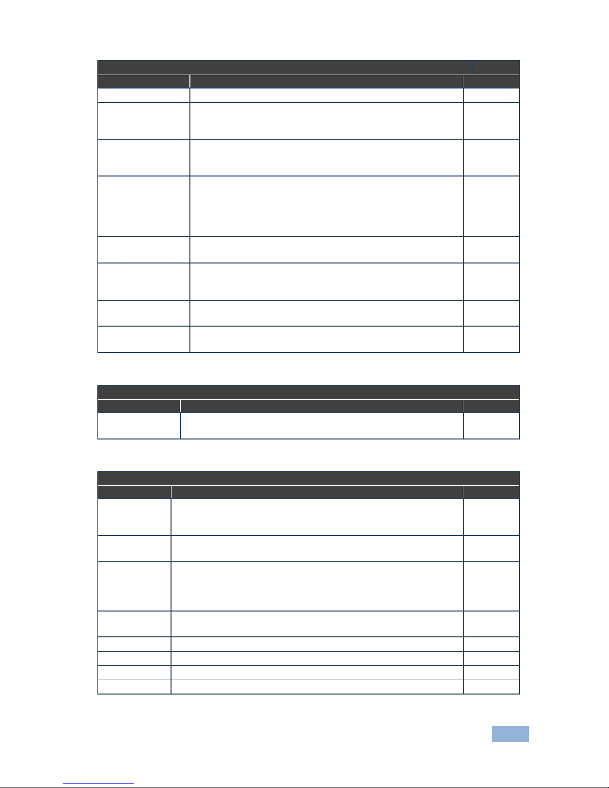
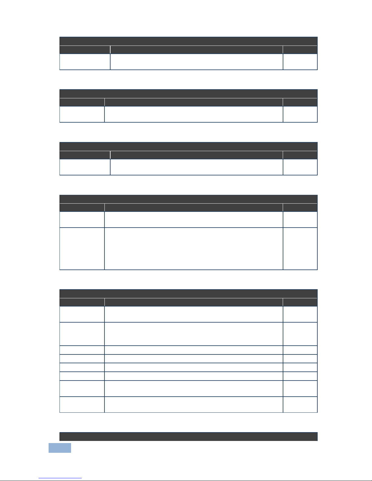
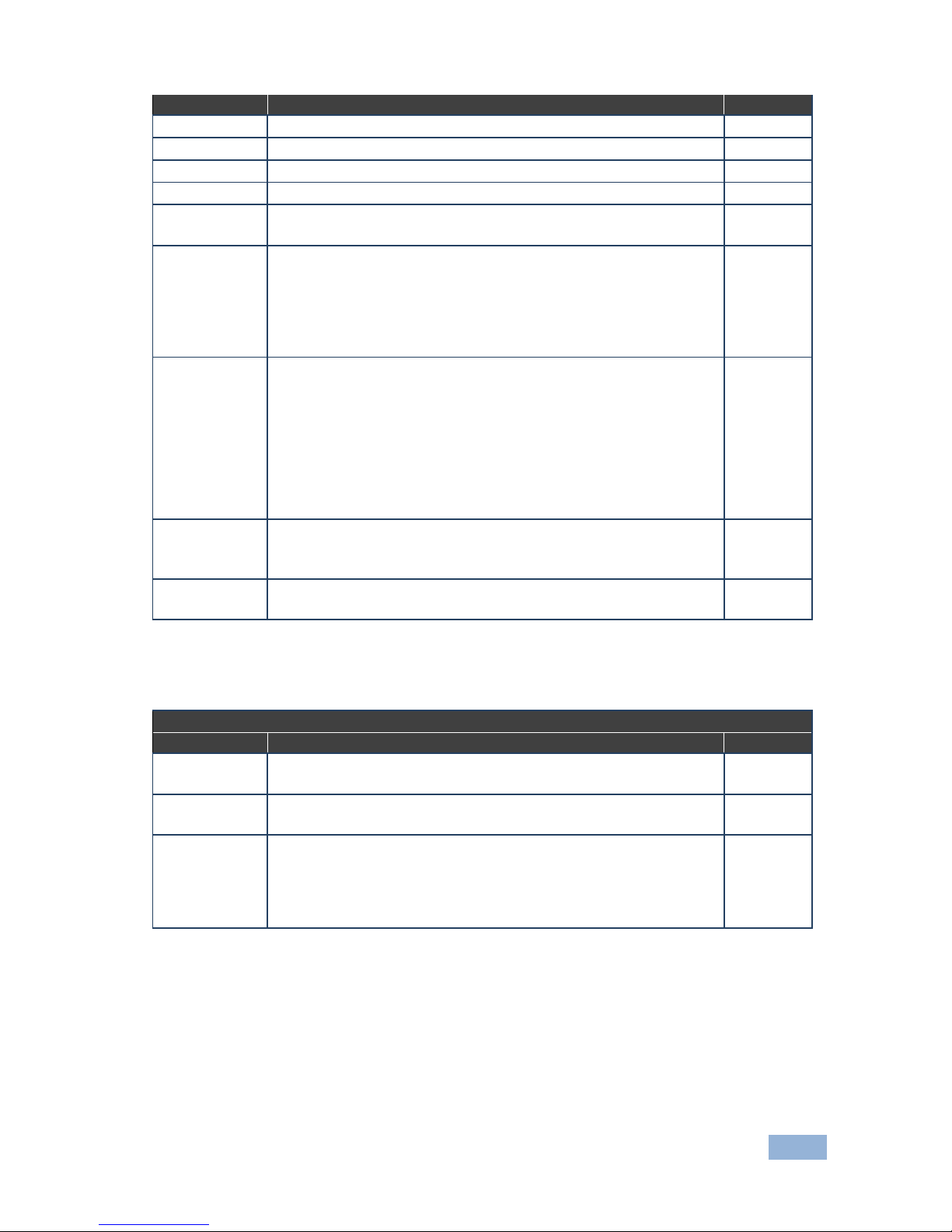
type of card installed and whether the card is an input or an output card. Tables
listing input cards and their parameters can be found at the end of this section.
To set parameters for a port:
1. Press MENU twice.
The following message is displayed:
start configuration menu
MENU to view setup ENT to change them
2. Press MENU until a display similar to the following is shown:
IN: 01 02 03 04 05 06 07 08 09 10 11
SET: X X X X 0 0 0 0 X X X
X indicates that there are no modifiable parameters for the associated port
and 0 indicates that there are modifiable parameters for the associated port.
3. Press TAKE to enter the list of ports.
The cursor flashes on a selected port.
4. Select the required port to modify using the left and right arrow buttons.
Page 45

40
VS-1616D-MD - Using the Configuration Menus
5. Press TAKE to enter the parameters list.
A message similar to the following is displayed with the relevant port number
in place of 06:
IN: 06
SET: 36.Reset SubBoard
6. To select the next parameter press the right arrow button. (See the table at
the end of this section for available parameters.)
Or:
7. To enter the displayed parameter press TAKE.
The parameter options are displayed.
8. Select the required action or number using the keypad numbers and arrows.
9. Press TAKE to save the change.
Note: The parameter change is not implemented until you press TAKE.
10. Repeat from Step 6 to modify other parameters
11. Do one of the following:
Press BREAKAWAY to exit the Config Menu
Wait approximately 15 seconds for the operation to time out
Press MENU to exit to the parameter list
The following tables list the input card types and their relevant parameters.
Note: Not all options are displayed for every menu selection. Some parameters
depend on the specific selection of other parameters.
Note: The volume control provides only attenuation, no gain. Hence, setting
volume to 100% provides no attenuation.
Page 46
VS-1616D-MD - Using the Configuration Menus
41
Analog Audio plus Digital Audio Input Card
Parameter
Description
Default
Pattern
RGB Bar, Black
RGB Bar
Reset Input
Re-power: Power cycles the port.
Factory Reset: Performs a factory reset of the port to default
values
Re-power
Audio Select
Auto.
AUD-Digital: Digital audio is selected.
AUD-Analog: Analog audio from the 3.5mm mini jack is selected
Auto
Audio Mute
MUTE: Mutes the audio input.
Non-MUTE: Unmutes the audio input.
Note: When set to Mute, any change to the audio parameters
automatically sets this to unmute.
Note: Not applicable when digital audio is selected
NonMUTE
Volume
Sets the audio output volume (0–70).
Note: Not applicable when digital audio is selected
50
Audio Balance
Sets the audio output channel balance (0–100).
Note: Not applicable when digital audio is selected. Applies to
analog inputs and outputs only
50
Audio Bass
Sets the audio output bass level (0–15).
Note: Not applicable when digital audio is selected
7
Audio Treble
Sets the audio output treble level (0–15).
Note: Not applicable when digital audio is selected
7
DGKat plus RS-232 Input Card
Parameter
Description
Default
HDCP
Turn HDCP on and off
*0=EN, 1=DIS
0
DisplayPort plus Analog Audio Input Card
Parameter
Description
Default
Reset Input
Re-power—Power cycles the port.
Factory default—Performs a factory reset to default values of the
port
Re-power
HDCP
Turn HDCP on and off .
*0=EN, 1=DIS
0
Audio Select
Auto—Audio signal selection is controlled by the presence or
absence of a plug in the 3.5mm mini jack.
AUD-Embedded—HDMI audio is selected.
AUD-Analog—Analog audio is selected
Auto
Audio Mute
MUTE: mutes the audio input.
Non-MUTE: unmutes the audio input
NonMUTE
Volume
Sets the audio output volume (0–70)
50
Audio Balance
Sets the audio output channel balance (0–100)
50
Audio Bass
Sets the audio output bass level (0–15)
7
Audio Treble
Sets the audio output treble level (0–15)
7
Page 47
42
VS-1616D-MD - Using the Configuration Menus
DVI (HDCP) Input Card
Parameter
Description
Default
HDCP
Turn HDCP on and off.
*0=EN, 1=DIS
0
HDMI (HDCP) Input Card
Parameter
Description
Default
HDCP
Turn HDCP on and off.
*0=EN, 1=DIS
0
HDMI (over fiber optic cable) with 670 module Input Card
Parameter
Description
Default
HDCP
Turn HDCP on and off .
*0=EN, 1=DIS
0
HDMI (over HDBT) plus IR, RS-232 and Ethernet Input Card
Parameter
Description
Default
HDCP
Turn HDCP on and off.
*0=EN, 1=DIS
0
XTRA
Enables range extender. Off for distances of up to 100m at 1080p
@60Hz @36bpp; On for distances of up to 150m at 1080p @60Hz
@24bpp
*0:ON, 1:OFF
Note: The range can be increased by approximately 30% by using
Kramer high quality cables, such as, the BC-HDKat6a
1
HDMI plus Analog Audio Input Card
Parameter
Description
Default
Reset Input
Re-power: Power cycles the port.
Factory: Performs a factory reset to default values of the port
Re-power
HDCP
Turn HDCP on and off.
*0=EN, 1=DIS
Note: Analog audio is still transmitted when HDCP is disabled
0
Volume
Sets the audio output volume (0–70)
50
Audio Balance
Sets the audio output channel balance (0–100)
50
Audio Bass
Sets the audio output bass level (0–15)
7
Audio Treble
Sets the audio output treble level (0–15)
7
Audio Mute
MUTE: Mutes the audio input
Non-MUTE: Unmutes the audio input
NonMUTE
Audio Select
AUD-Digital: Digital audio is selected.
AUD-Analog: Analog audio from the 3.5mm mini jack is selected
AUDDigital
HDMI UHD plus Analog Audio Input Card
Page 48
VS-1616D-MD - Using the Configuration Menus
43
Parameter
Description
Default
Volume
Sets the audio output volume (0–70)
50
Audio Balance
Sets the audio output channel balance (0–100)
50
Audio Bass
Sets the audio output bass level (0–15)
7
Audio Treble
Sets the audio output treble level (0–15)
7
Audio Mute
MUTE: Mutes the audio input.
Non-MUTE: Unmutes the audio input
NonMUTE
Audio Select
AUTO: If a plug is inserted into the 3.5mm mini jack, analog audio is
selected. If no plug is inserted, digital audio is selected.
AUD-Digital: Digital audio is selected.
AUD-Analog: Analog audio from the 3.5mm mini jack is selected.
Note: This parameter is not displayed when the ST parameter is set
to either 1 or 2
AUTO
ST
Selects the manner in which the analog audio port functions.
ST=0: Input. If an analog source is connected, the port acts as an
input and embeds the audio into the HDMI signal that goes to the
matrix.
ST=1: Output. The audio is de-embedded from the HDMI source and
is output as analog audio. (Note: The 3.5mm mini jack connector
acts as an output in this case!)
ST=2: ARC. The audio is taken from the 3.5mm mini jack connector
and sent to the ARC device which is connected to the HDMI input
0
HDCP
Turn HDCP on and off.
*0=EN, 1=DIS
Note: Analog audio is still transmitted when HDCP is disabled
0
Reset Input
Re-power: Power cycles the port.
Factory: Performs a factory reset to default values of the port
Re-power
HDMI plus S/PDIF Audio Input Card
Parameter
Description
Default
Reset Input
Re-power: Power cycles the port.
Factory: Performs a factory reset to default values of the port
Re-power
HDCP
Turn HDCP on and off.
*0=EN, 1=DIS
0
Audio Select
Auto: Audio signal selection is controlled by the presence or
absence of a plug in the 3.5mm mini jack.
AUD-Embedded: HDMI audio is selected.
AUD-Ex-Digital: S/PDIF audio is selected (only works on HDMI plus
S/PDIF card)
Auto
Page 49
44
VS-1616D-MD - Using the Configuration Menus
HDMI UHD (over HDBaseT 70m) plus IR and RS-232 Input Card
Parameter
Description
Default
HDCP
Turn HDCP on and off.
*0=EN, 1=DIS
0
SDI plus Analog Audio Input Card
Parameter
Description
Default
Color Space
RGB, YUV422, YUV444
RGB
Reset Input
Re-power: Power cycles the port.
Factory default: Performs a factory reset to default values of the port
Re-power
Audio Select
Auto: Audio signal selection is controlled by the presence or
absence of a plug in the 3.5mm mini jack.
AUD-Embedded: HDMI audio is selected.
AUD-Analog: Analog audio is selected
Auto
SDI_AUDIO_
SWITCH
Selects the SDI audio channel
0, 1, 2, 3, 4, 5, 6, 7, 8, 9, 10, 11, 12, 13, 14, 15
0
Test Video plus Analog Audio Card Input
Parameter
Description
Default
Reset Input
Re-power: Power cycles the port
Factory: Performs a factory reset to default values of the port
Re-power
Audio Select
Auto: Audio signal selection is controlled by the presence or
absence of a plug in the 3.5mm mini jack.
AUD-Embedded: HDMI audio is selected.
AUD-Analog: Analog audio is selected
Auto
Volume
Sets the audio output volume (0–70)
35
Audio Balance
Sets the audio output channel balance (0–100)
50
Audio Bass
Sets the audio output bass level (0–15)
7
Audio Treble
Sets the audio output treble level (0–15)
7
Audio Mute
MUTE: Mutes the audio input
Non-MUTE: Unmutes the audio input
NonMUTE
Page 50
VS-1616D-MD - Using the Configuration Menus
45
VGA plus Analog Audio Input Card
Parameter
Description
Default
Resolution Detect
Auto, User Defined, Auto Adjust, (see note below table)
Auto
Phase Mode
Auto, User Define, Auto Adjust, (see note below table)
Auto
Brightness
(0–63)
32
Contrast
(0–63)
32
Phase adjustment
(0–63)
Note: This adjustment is only valid when Phase Mode Is set to
User Defined mode.
As
detected
Reset Input
Re-power: Power cycles the port
Factory: Performs a factory reset of the port to default values
Re-power
Hor-Total Pixels
Set the value for total horizontal pictures.
(0–9999)
As
detected
Horizontal-Start
Set the value for horizontal start.
(0–16383)
As
detected
Horizontal-Active
Set the value for horizontal active pixels.
(0–16383)
As
detected
Vertical-Start
Set the value for vertical start.
(0–255)
As
detected
Vertical-Active
Set the value for vertical active pixels.
(0–16383)
As
detected
Restore Setup
(1–36)
1
Recall Setup
(1–32)
1
Save Timing Para
(0–127)
0
Recall Timing Para
(0–127)
0
Volume
Sets the audio output volume (0–70)
50
Audio Balance
Sets the audio output channel balance (0–100)
50
Audio Bass
Sets the audio output bass level (0–15)
7
Audio Treble
Sets the audio output treble level (0–15)
7
Audio Mute
MUTE: Mutes the audio input
Non-MUTE: Unmutes the audio input
Note: When set to Mute, any change to the audio parameters
automatically sets this to unmute
NonMUTE
R-offset
(0–63)
32
G-offset
(0–63)
32
B-offset
(0–63)
32
R-gain
(0–63)
32
G-gain
(0–63)
32
B-gain
(0–63)
32
Note: The Auto Adjust feature requires the device to re-calculate the parameters
based on the currently connected source. The result may be different from the
standard parameters for the currently set resolution. The result is saved in nonvolatile memory and is recalled when the same source is used again. In order to
revert to auto pre-defined parameters, you should either reset to factory setting
with the relevant source connected or connect a different source.
Page 51

46
VS-1616D-MD - Using the Configuration Menus
8.2.3 Config Menu—Output Load Detection Display
This option displays a list of outputs and indicates which have loads attached to
them.
To display a list of outputs and attached loads:
1. Press MENU twice.
The following message is displayed:
start configuration menu
MENU to view setup, ENT to change them
2. Press MENU until the following is displayed:
OUT: 01 02 03 04 05 06 07 08 09 10 11
LOAD: Y X Y Y Y Y X Y Y Y X
Y indicates that a load is attached and X indicates that no load is detected
on the relevant output.
3. Do one of the following:
Press BREAKAWAY to exit the Config Menu
Wait approximately 15 seconds for the operation to time out
Press MENU to move to the next Config Menu option
8.2.4 Config Menu—Output Port Parameter Setting
This option sets port specific parameters. Ports that show an X have no
parameters available to modify. Ports that show a 0 have parameters available to
modify. The parameters that are available, such as, audio balance, depend on the
type of card installed and whether the card is an input or an output card. Tables
listing output cards and their parameters can be found at the end of this section.
To set parameters for a port:
1. Press MENU twice.
The following message is displayed:
start configuration menu
MENU to view setup ENT to change them
Page 52

VS-1616D-MD - Using the Configuration Menus
47
2. Press MENU until a display similar to the following is shown:
OUT: 01 02 03 04 05 06 07 08 09 10 11
SET: X X X X 0 0 0 0 X X X
X indicates that there are no modifiable parameters for the associated port
and 0 indicates that there are modifiable parameters for the associated port.
3. Press TAKE to enter the list of ports.
The cursor flashes on a selected port.
4. Select the required port to modify using the left and right arrow buttons.
5. Press TAKE to enter the parameters list.
A message similar to the following is displayed with the relevant port number
in place of 06:
OUT: 06
SET: 36.Reset SubBoard
6. To select the next parameter press the right arrow button. (See the table at
the end of this section for available parameters.)
Or:
7. To enter the displayed parameter press TAKE.
The parameter options are displayed.
8. Select the required action or number using the keypad numbers and arrows.
9. Press TAKE to save the change.
Note: The parameter change is not implemented on the system until you
press TAKE.
10. Repeat from Step 6 to modify other parameters
11. Do one of the following:
Press BREAKAWAY to exit the Config Menu
Wait approximately 15 seconds for the operation to time out
Press MENU to exit to the parameter list
Page 53
48
VS-1616D-MD - Using the Configuration Menus
The following tables list the output port types and their relevant parameters.
Note: Not all options are displayed for every menu selection. Some parameters
depend on the specific selection of other parameters.
Analog Audio plus Digital Audio Output Card
Parameter
Description
Default
Reset Output
Re-power: Power cycles the port
Factory Reset: Performs a factory reset of the port to default
values
Re-power
Volume
Sets the audio output volume (0–70)
Note: Not applicable when digital audio is selected
50
Audio Balance
Sets the audio output channel balance (0–100)
Note: Not applicable when digital audio is selected
50
Audio Bass
Sets the audio output bass level (0–15)
Note: Not applicable when digital audio is selected
7
Audio Treble
Sets the audio output treble level (0–15)
Note: Not applicable when digital audio is selected
7
Audio Mute
MUTE: Mutes the audio output
Non-MUTE: Unmutes the audio output
Note: When set to Mute, any change to the audio parameters
automatically sets this to unmute
Note: Not applicable when digital audio is selected
NonMUTE
Audio MONO
OFF—Analog output is stereo
MIX—Analog output is mono
OFF
DGKat plus RS-232 Output Card
Parameter
Description
Default
HDMI
Sets the output signal format (Display, HDMI, DVI).
Display—the output is set automatically based on the EDID of the
connected display.
DVI—Force the output to be DVI.
HDMI—Force the output to be HDMI.
Note: When selecting the DVI option and fast switching is
enabled, you must ensure that the source is DVI compatible
Display
Deep Color
Sets maximum color bit depth (Auto, 8 bit).
Auto—Set the color depth automatically.
8 bit—Limit the color depth to 8 bits.
Note: Deep color on DGKat is not supported at higher resolutions
(1080p @50/60Hz or WUXGA). When setting deep color to on,
ensure that the resolution does not exceed the DGKat maximum
data rate of 4.95Gbps (1.65Gbps per graphic channel)
Off
Switch Speed
When switching between different sources the switching time can
be reduced by setting the fast switch level (Ex-fast Switch, Fast
Switch or Normal Switch) by reducing color depth to 8-bits
Normal
Switch
Page 54
VS-1616D-MD - Using the Configuration Menus
49
DisplayPort plus Analog Audio Card Output
Parameter
Description
Default
Reset Output
Re-power—Power cycles the port
Factory—Performs a factory reset to default values of the port
Re-power
Audio Mute
MUTE—Mutes the audio input
Non-MUTE—Unmutes the audio input
NonMUTE
Volume
Sets the audio output volume (0–100)
50
Audio Balance
Sets the audio output channel balance (0–100)
50
Audio Bass
Sets the audio output bass level (0–15)
7
Audio Treble
Sets the audio output treble level (0–15)
7
Audio MONO
OFF—Analog output is stereo
MIX—Analog output is mono
MIX
DVI (HDCP) Output Card
Parameter
Description
Default
HDMI
Sets the output signal format (Display, HDMI, DVI).
Display—The output is set automatically based on the EDID of the
connected display.
DVI—Force the output to be DVI.
HDMI—Force the output to be HDMI.
Note: When selecting the DVI option and fast switching is
enabled, you must ensure that the source is DVI compatible
Display
Deep Color
Sets maximum color bit depth (Auto, 8 bit).
Auto—Set the color depth automatically.
8 bit—Limit the color depth to 8 bits
Auto
Switch Speed
When switching between different sources the switching time can
be reduced by setting the fast switch level (Ex-fast Switch, Fast
Switch or Normal Switch) by reducing color depth to 8-bits
Normal
Switch
HDMI (HDCP) Output Card
Parameter
Description
Default
HDMI
Sets the output signal format (Follow input, HDMI, DVI).
Display—The output is set automatically based on the EDID of the
connected display.
DVI—Force the output to be DVI.
HDMI—Force the output to be HDMI.
Note: When selecting the DVI option and fast switching is
enabled, you must ensure that the source is DVI compatible
Follow
Deep Color
Sets maximum color bit depth (Auto, 8 bit).
Auto—Set the color depth automatically.
8 bit—Limit the color depth to 8 bits
Auto
Switch Speed
When switching between different sources the switching time can
be reduced by setting the fast switch level (Ex-fast Switch, Fast
Switch or Normal Switch) by reducing color depth to 8-bits
Normal
Switch
Page 55
50
VS-1616D-MD - Using the Configuration Menus
HDMI (over fiber optic cable) with 670 module (HDCP) Output Card
Parameter
Description
Default
HDMI
Sets the output signal format (Display, HDMI, DVI).
Display—The output is set automatically based on the EDID of the
connected display.
DVI—Force the output to be DVI.
HDMI—Force the output to be HDMI.
Note: When selecting the DVI option and fast switching is
enabled, you must ensure that the source is DVI compatible
Display
Deep Color
Sets maximum color bit depth (Auto, 8 bit).
Auto—Set the color depth automatically.
8 bit—Limit the color depth to 8 bits
Auto
Switch Speed
When switching between different sources the switching time can
be reduced by setting the fast switch level (Ex-fast Switch, Fast
Switch or Normal Switch) by reducing color depth to 8-bits
Normal
Switch
HDMI (over HDBT) plus IR, RS-232 and Ethernet Output Card
Parameter
Description
Default
HDMI
Sets the output signal format (Display, HDMI, DVI).
Display—The output is set automatically based on the EDID of the
connected display.
DVI—Force the output to be DVI.
HDMI—Force the output to be HDMI.
Note: When selecting the DVI option and fast switching is
enabled, you must ensure that the source is DVI compatible
Display
Deep Color
Sets maximum color bit depth (Auto, 8 bit).
Auto—Set the color depth automatically.
8 bit—Limit the color depth to 8 bits
Auto
Switch Speed
When switching between different sources the switching time can
be reduced by setting the fast switch level (Ex-fast Switch, Fast
Switch or Normal Switch) by reducing color depth to 8-bits
Normal
Switch
XTRA
Enables range extender. Off for distances of up to 100m at 1080p
@60Hz @36bpp; On for distances of up to 150m at 1080p
@60Hz @24bpp
*0:ON, 1:OFF
Note: Using Kramer high quality cables such as the BC-HDKat6a
can increase the range by approximately 30%
1
Page 56
VS-1616D-MD - Using the Configuration Menus
51
HDMI UHD plus Analog Audio Output Card
Parameter
Description
Default
Volume
Sets the audio output volume (0–70)
50
Audio Balance
Sets the audio output channel balance (0–100)
50
Audio Bass
Sets the audio output bass level (0–15)
7
Audio Treble
Sets the audio output treble level (0–15)
7
Audio Mute
MUTE: Mutes the audio output.
Non-MUTE: Unmutes the audio output.
Note: When set to Mute, any change to the audio parameters
automatically sets this to unmute
NonMUTE
Audio Mono
OFF—Analog output is stereo
MIX—Analog output is mono
OFF
Audio Select
AUTO: If a plug is inserted into the 3.5mm mini jack, analog audio
is selected. If no plug is inserted, digital audio is selected.
AUD-Digital: Digital audio is selected.
AUD-Analog: Analog audio from the 3.5mm mini jack is selected.
Note: This parameter is not displayed when the ST parameter is
set to either 1 or 2
AUTO
ST
Selects the manner in which the analog audio port functions.
0=Input. If an analog source is connected, the 3.5mm mini jack
connector acts as an input and embeds the audio into the HDMI
output signal.
1=Output. The audio is de-embedded from the HDMI signal routed
to this card, and is output as analog audio with the 3.5mm mini
jack connector acting as an output.
2=ARC. The audio is taken from the sink that supports ARC and is
output as analog audio on the 3.5mm mini jack connector
1
Switch Speed
When switching between different sources the switching time can
be reduced by setting the fast switch level (Fast Switch or
Normal Switch) by reducing color depth to 8-bits
Normal
Switch
Reset Output
Re-power: power cycle the port
Factory default: perform a factory reset of the port to default
values
Re-power
Page 57
52
VS-1616D-MD - Using the Configuration Menus
HDMI plus Analog Audio Output Card
Parameter
Description
Default
Reset Output
Re-power: power cycle the port
Factory default: perform a factory reset of the port to default
values
Re-power
HDMI
Sets the output signal format (Follow input, HDMI, DVI).
Display—the output is set automatically based on the EDID of the
connected display.
DVI—Force the output to be DVI.
HDMI—Force the output to be HDMI.
Note: When selecting the DVI option and fast switching is
enabled, you must ensure that the source is DVI compatible
Follow
Deep Color
Sets maximum color bit depth (Auto, 8 bit).
Auto—Set the color depth automatically.
8 bit—Limit the color depth to 8 bits
Auto
Switch Speed
When switching between different sources the switching time can
be reduced by setting the fast switch level (Ex-fast Switch, Fast
Switch or Normal Switch) by reducing color depth to 8-bits
Normal
Switch
Volume
Sets the audio output volume (0–70)
50
Audio Balance
Sets the audio output channel balance (0–100)
50
Audio Bass
Sets the audio output bass level (0–15)
7
Audio Treble
Sets the audio output treble level (0–15)
7
Audio Mute
MUTE: mutes the audio output
Non-MUTE: unmutes the audio output
Note: When set to Mute, any change to the audio parameters
automatically sets this to unmute
NonMUTE
Audio Mono
OFF—Analog output is stereo
MIX—Analog output is mono
OFF
HDMI plus S/PDIF Audio Output Card
Parameter
Description
Default
Reset Output
Re-power: power cycle the port
Factory default: perform a factory reset to default values of the
port
Re-power
HDMI
Sets the output signal format (Follow input, HDMI, DVI).
Display—the output is set automatically based on the EDID of the
connected display.
DVI—Force the output to be DVI.
HDMI—Force the output to be HDMI.
Note: When selecting the DVI option and fast switching is
enabled, you must ensure that the source is DVI compatible
Follow
Deep Color
Sets maximum color bit depth (Auto, 8 bit).
Auto—Set the color depth automatically.
8 bit—Limit the color depth to 8 bits
Auto
Switch Speed
When switching between different sources the switching time can
be reduced by setting the fast switch level (Ex-fast Switch, Fast
Switch or Normal Switch) by reducing color depth to 8-bits
Normal
Switch
Page 58
VS-1616D-MD - Using the Configuration Menus
53
HDMI Scaler Output Card
Parameter
Description
Default
HDMI
Sets the output signal format.
Display—The output is set automatically based on the EDID of
the connected display.
HDMI— Force the output to be HDMI.
DVI— Force the output to be DVI
Display
Deep Color
Sets maximum color bit depth (Auto, 8 bit).
Auto—Set the color depth automatically.
8 bit—Limit the color depth to 8 bits
Auto
Reset Output
Re-power—Power cycle the port.
Factory default—Perform a factory reset to default values of the
port
Re-power
Video-Freeze
Freezes/unfreezes the output video.
Off
On
Off
Picture Aspect
Ratio
Sets the picture aspect ratio.
Full
Crop
Best-Fit
Best-Fit
Out Resolution
Sets the output video resolution.
640x480x60
1024x768x60
1280x1024x60
1600x1200x60 (see note below table)
1920x1080px60
1920x1080px50
1280x720px60
1280x720px50
720x480px60
800x600x60
1900x1200x60 (see note below table)
720x576px50
Native
1920x1080px
60
FPGA VER:
7D-03
FW VER:
4.0_0006
SPEC
VER:0107
DB:
21200025C30
00
0 1 0
Note: To ensure a stable output signal using either WUXGA (1920X1200) or
UXGA (1600X1200), set the output to 8 bit color depth in the Deep Color menu.
Page 59
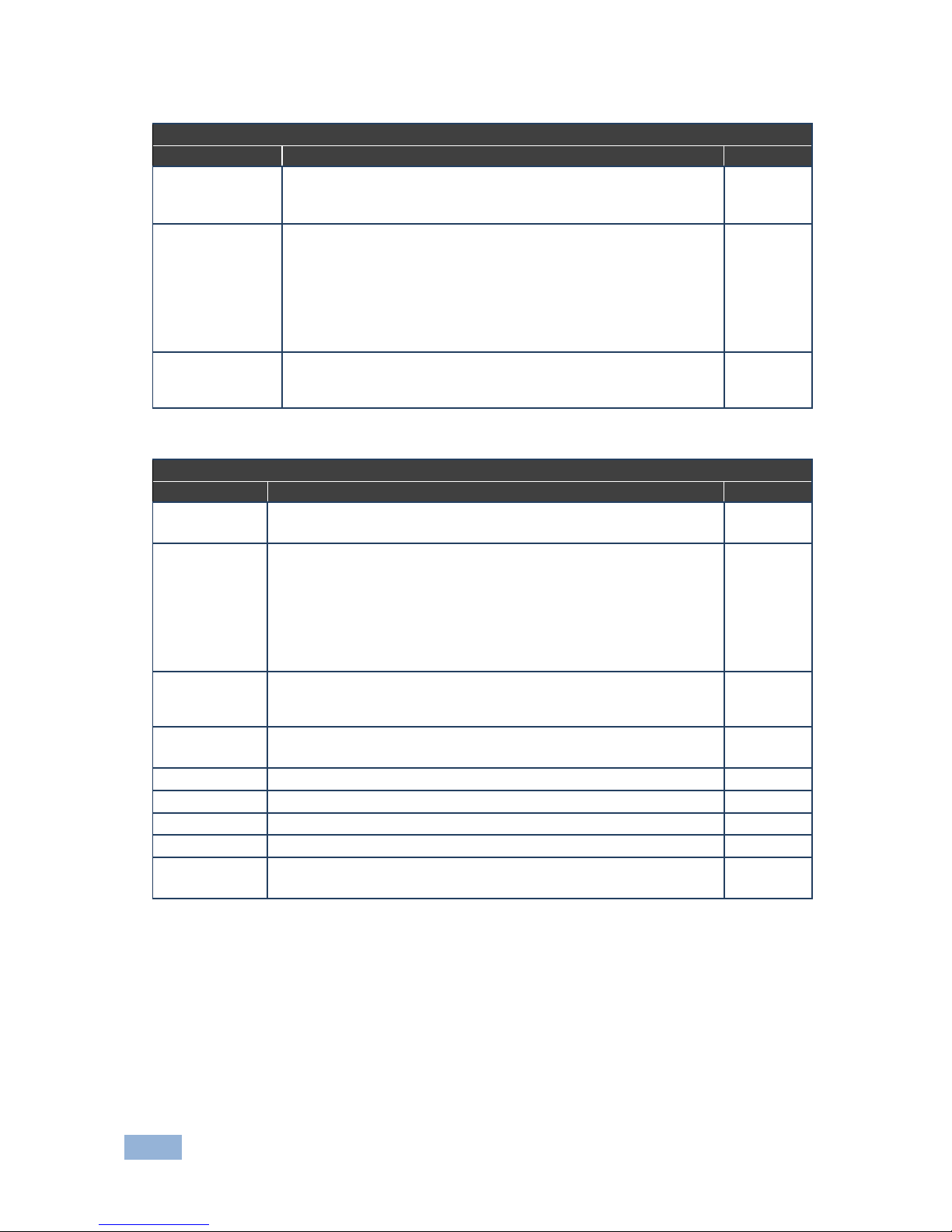
54
VS-1616D-MD - Using the Configuration Menus
HDMI UHD (over HDBaseT 70m) plus IR and RS-232 Output Card
Parameter
Description
Default
Reset Output
Re-power: power cycle the port
Factory default: perform a factory reset to default values of the
port
Re-power
HDMI
Sets the output signal format (Display, HDMI, DVI).
Display—the output is set automatically based on the EDID of the
connected display.
DVI—Force the output to be DVI.
HDMI—Force the output to be HDMI.
Note: When selecting the DVI option and fast switching is
enabled, you must ensure that the source is DVI compatible
Display
Switch Speed
When switching between different sources the switching time can
be reduced by setting the fast switch level (Ex-fast Switch, Fast
Switch or Normal Switch) by reducing color depth to 8-bits
Normal
Switch
Test Video plus Analog Audio Card Output
Parameter
Description
Default
Reset Input
Re-power: power cycles the port
Factory: performs a factory reset to default values of the port
Re-power
HDMI
Sets the output signal format (Display, HDMI, DVI).
Display—the output is set automatically based on the EDID of the
connected display.
DVI—Force the output to be DVI.
HDMI—Force the output to be HDMI.
Note: When selecting the DVI option and fast switching is enabled,
you must ensure that the source is DVI compatible
Display
Switch Speed
When switching between different sources the switching time can be
reduced by setting the fast switch level (Ex-fast Switch, Fast Switch
or Normal Switch) by reducing color depth to 8-bits
Normal
Switch
Audio Mute
MUTE: mutes the audio input
Non-MUTE: unmutes the audio input
NonMUTE
Volume
Sets the audio output volume (0–70)
50
Audio Balance
Sets the audio output channel balance (0–100)
50
Audio Bass
Sets the audio output bass level (0–15)
7
Audio Treble
Sets the audio output treble level (0–15)
7
Audio Mono
OFF—Analog output is stereo
MIX—Analog output is mono
OFF
Page 60
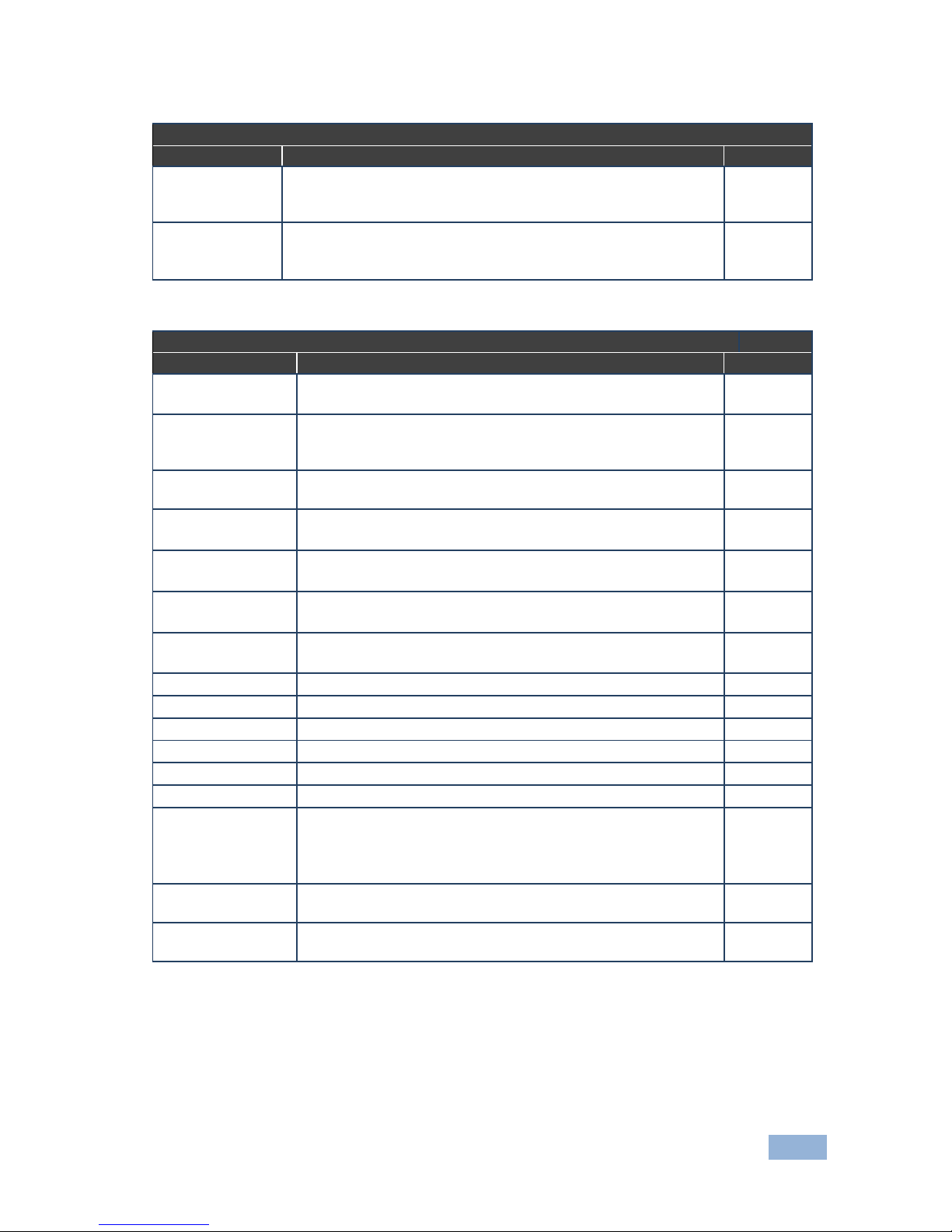
VS-1616D-MD - Using the Configuration Menus
55
VGA Output Card
Parameter
Description
Default
Switch Speed
When switching between different sources the switching time can
be reduced by setting the fast switch level (Ex-fast Switch, Fast
Switch or Normal Switch) by reducing color depth to 8-bits
Normal
Switch
Reset Output
Re-power: power cycle the port
Factory default: perform a factory reset to default values of the
port
Re-power
VGA plus Analog Audio Output Card
Parameter
Description
Default
Reset Output
Re-power: power cycles the port
Factory: performs a factory reset of the port to default values
Re-power
Switch Speed
When switching between different sources the switching time
can be reduced by setting the fast switch level (Ex-fast Switch,
Fast Switch or Normal Switch) by reducing color depth to 8-bits
Normal
Switch
Hor-Total Pixels
Set the value for total horizontal pictures.
(0–9999)
As
detected
Horizontal-Start
Set the value for horizontal start.
(0–16383)
As
detected
Horizontal-Active
Set the value for horizontal active pixels.
(0–16383)
As
detected
Vertical-Start
Set the value for vertical start.
(0–255)
As
detected
Vertical-Active
Set the value for vertical active pixels.
(0–16383)
As
detected
Save Timing Para
(0–127)
0
Recall Timing Para
(0–127)
0
Volume
Sets the audio output volume (0–70)
50
Audio Balance
Sets the audio output channel balance (0–100)
50
Audio Bass
Sets the audio output bass level (0–15)
7
Audio Treble
Sets the audio output treble level (0–15)
7
Audio Mute
MUTE: mutes the audio input
Non-MUTE: unmutes the audio input
Note: When set to Mute, any change to the audio parameters
automatically sets this to unmute
NonMUTE
OUT_HSYNC_
INVERT
Sets the H_SYNC invert.
(0, 1)
0
OUT_VSYNC_
INVERT
Sets the V_SYNC invert.
(0, 1)
0
Page 61

56
VS-1616D-MD - Using the Configuration Menus
8.2.5 Config Menu—Interface Configuration
This option lets you activate or deactivate the IR (infrared) and Ethernet interfaces.
To activate or deactivate the IR or Ethernet interfaces:
1. Press MENU twice.
The following message is displayed:
start configuration menu
MENU to view setup ENT to change them
2. Press MENU until the following is displayed:
INTERFACE configuration
current:IR-ON Ethernet-ON
The current status of the IR and Ethernet interfaces is displayed.
3. Press ENT to select the Interface Submenu.
4. Select 1 to modify the status of the IR interface or 2 to modify that status of
the Ethernet interface (in this example, 2).
The following is displayed:
Ethernet interface setup
1:make it ACTIVE 2:turn it OFF
5. Press 1 to activate the interface or 2 to deactivate it.
6. Press TAKE to confirm the action.
The interface status is changed. After a few seconds the next option on the
Config Menu is displayed.
8.2.6 Config Menu—Interface Reply Configuration
This option lets you switch the Reply configuration on or off. Setting Reply to on
causes all interfaces that are set to on to accept and execute commands, and also
to reply. Setting Reply to off causes all interfaces that are set to on to accept and
execute commands, but not to reply.
Page 62

VS-1616D-MD - Using the Configuration Menus
57
To switch the Reply configuration on or off:
1. Press MENU twice.
The following message is displayed:
start configuration menu
MENU to view setup ENT to change them
2. Press MENU until the following is displayed:
interface REPLY configuration
current interface REPLY – ON
This indicates the current Reply configuration status.
3. Press ENT to enter the Reply Submenu.
The following is displayed:
interface REPLY configuration
1:turn REPLY ON 2:never REPLY
4. Press 1 to switch Reply on or 2 to switch it off.
5. Press TAKE to confirm the action.
A message is displayed indicating the new status of the Reply configuration.
After a few seconds the next option on the Config Menu is displayed.
8.2.7 Config Menu—Protocol Configuration
The VS-1616D-MD supports Kramer Protocol 2000 and Protocol 3000.
To switch from Protocol 3000 (default) to Protocol 2000:
1. Press MENU twice.
The following message is displayed:
start configuration menu
MENU to view setup ENT to change them
2. Press MENU until the following is displayed:
PROTOCOL configuration
Current: Kramer-3000
This indicates the current Protocol setting.
Page 63

58
VS-1616D-MD - Using the Configuration Menus
3. Press ENT to enter the Reply Submenu.
The following is displayed:
PROTOCOL configuration
1:KRAMER-2000 2:KRAMER-3000
4. Press 1 to switch to Protocol 2000.
The following is displayed:
Set PROTOCOL to KRAMER-2000?
press TAKE to confirm
5. Press TAKE to confirm the action.
A message is displayed indicating the new Protocol status. After a few
seconds the next option on the Config Menu is displayed.
8.2.8 Config Menu—Store Default Setup
This option lets you store the current setup as the default setup. The default setup
can be recalled at any time using the DEFAULT SETUP button (see
Section 7.4.5).
Note: This is not the setup that is loaded when the unit is switched on.
To store the current setup as the default setup:
1. Press MENU twice.
The following message is displayed:
start configuration menu
MENU to view setup ENT to change them
2. Press MENU until the following is displayed:
store DEFAULT setup
press ENTER to store
3. Press ENT to store the current configuration as the default configuration.
The following is displayed:
current matrix stage is OKAY?
press TAKE to confirm
Page 64

VS-1616D-MD - Using the Configuration Menus
59
4. Press TAKE.
The following is displayed:
current matrix stage
store as DEFAULT setup
This indicates that the current setup is stored as the default setup. After a
few seconds the next option on the Config Menu is displayed.
8.2.9 Config Menu—Total Matrix Reset
This option lets you turn all outputs off or reset the unit to its factory default
settings.
To reset the matrix setup:
1. Press MENU twice.
The following message is displayed:
start configuration menu
MENU to view setup ENT to change them
2. Press MENU until the following is displayed:
TOTAL MATRIX RESET
exit = ESC ENT = submenu
3. Press ENT to enter the Reset Submenu.
The following is displayed:
COMPLETELY MATRIX RESET
1:ALL outputs OFF 2:Factory default
4. Press 1 to turn off all outputs or 2 to perform a factory reset of all options.
Warning:
Selecting option 2 to perform a factory default reset
clears all setups, options and configuration
5. Press TAKE and wait a few seconds.
The following is displayed:
Are you Absolutely sure !!!
Once more TAKE to confirm
Page 65

60
VS-1616D-MD - Using the Configuration Menus
6. Press TAKE.
The following is displayed:
Matrix erased!!!
Please, wait …
The matrix and device configuration are erased. After a few seconds the next
option on the Config Menu is displayed.
8.2.10 Config Menu—Display Firmware Versions
This option displays the main and front firmware versions.
To display the firmware versions:
1. Press MENU twice.
The following message is displayed:
start configuration menu
MENU to view setup ENT to change them
2. Press MENU until the following is displayed:
Main Firmware Version: 1.0
Front Firmware Version: 1.0
3. Either press BREAKAWAY to exit the Config Menu or wait approximately 15
seconds for the operation to time out.
Page 66

VS-1616D-MD - Configuring the Number of Installed Input and Output Ports
61
9 Configuring the Number of Installed Input
and Output Ports
After installing or removing a module you need to set the number of input and
output ports so that the VS-1616D-MD recognizes the new configuration. Refer to
Section 6.2 for an explanation of port numbering before setting the number of input
and output ports.
To set the number of input or output ports:
1. Press ESC, ENT and LOCK together.
The following is displayed:
Configuration Device
2. Press ENT.
The following is displayed:
Test Board: 0 MaxInput:32 MaxOutput:32
Note: The number of input and output ports can only be set in units of four, for
example, 4 x 4, 32 x 4 or 12 x 16, and not 5 x 4 or 12 x 17.
3. Using the numeric keys, enter the number of input and output ports installed.
The TAKE button flashes.
4. Press TAKE.
The number of installed ports is saved and the display reverts to the
output/input display.
5. Reboot the device by turning the power off and then on again.
Page 67

62
VS-1616D-MD - Installing and Using the Test Module to Troubleshoot Video Problems
10 Installing and Using the Test Module to
Troubleshoot Video Problems
The VS-1616D-MD includes a test module which acts as a signal generator and
can be used to diagnose video/audio issues in an operating environment.
The test module must be installed in the configuration before it can be used. When
installing the test module, the number of configured inputs and outputs must be
increased by one. For example:
If your VS-1616D-MD has four inputs and eight outputs, you must configure
the VS-1616D-MD as 5 x 9
If your VS-1616D-MD has 16 inputs and 16 outputs, you must configure the
VS-1616D-MD as 17 x 17
10.1 Installing the Test Module
To install the test module in the configuration:
1. Press ESC, ENT and LOCK together.
The following is displayed:
Configuration Device
2. Press ENT.
The following is displayed:
Test Board: 0 MaxInput:32 MaxOutput:32
where 0 indicates that the test module is not installed.
3. Using the numeric keys, press 1 to indicate that the test module is installed.
The TAKE button flashes.
4. Press TAKE.
5. Increase the number of configured inputs and outputs by one (see
Section 9).
Page 68
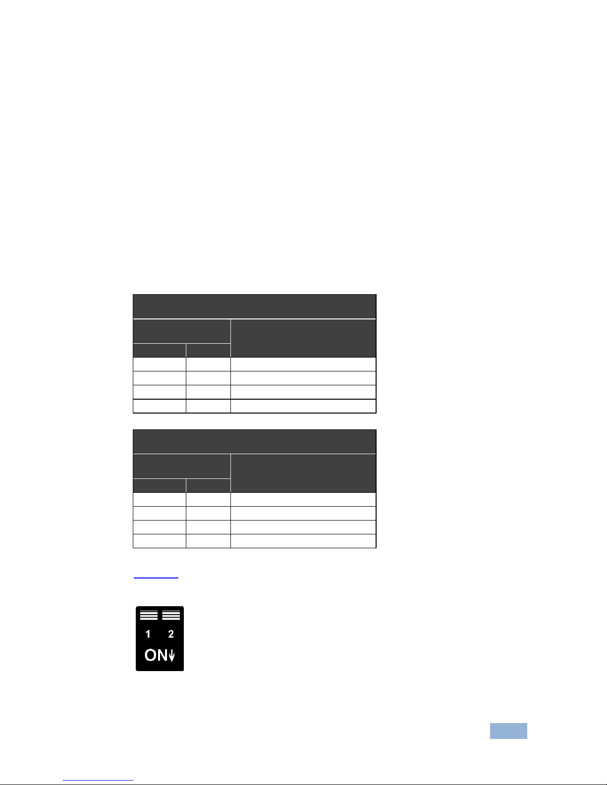
VS-1616D-MD - Installing and Using the Test Module to Troubleshoot Video Problems
63
6. Power cycle the device.
The test module is now installed and may be used.
10.2 Setting the Resolution of the Generated Video
The test module generates a range of both PC and HD resolutions which are
selected by a combination of DIP-switches and an on-board jumper (labeled #1).
Install the jumper to select HD resolutions or remove the jumper to select PC
resolutions.
The Resolution DIP-switch is used to set the resolution of the generated video as
listed in the tables below.
Available PC Resolutions for Generated Video
(Jumper off)
DIP-switch
Position
Resolution
1
2
OFF
OFF
1024 x 768 @60Hz (default)
ON
OFF
1280 x 1024 @60Hz
OFF
ON
1600 x 1200 @60Hz
ON
ON
1920 x 1200 @60Hz
Available HD Resolutions for Generated Video
(Jumper on, default)
DIP-switch
Position
Resolution
1
2
OFF
OFF
480p
ON
OFF
720p
OFF
ON
1080i
ON
ON
1080p
Figure 14 shows the Resolution DIP-switch with both switches off (up, default,
480p).
Figure 14: Resolution DIP-switch
Page 69
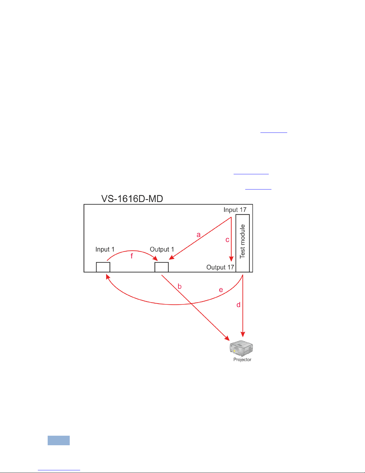
64
VS-1616D-MD - Installing and Using the Test Module to Troubleshoot Video Problems
10.3 Setting the Pattern of the Generated Video
The Pattern button is used to set the pattern of generated video. There are 32
available patterns. Press the button repeatedly to cycle through the patterns.
10.4 Using the Test Module to Troubleshoot Video Problems
The test module may be used in various ways to isolate video problems.
The following examples are based on the signal paths shown in Figure 15 and a
VS-1616D-MD device installed as follows:
16 inputs and 16 outputs
The test module is installed and configured (see Section 10.1)
17 configured inputs and 17 configured outputs (see Section 9)
Figure 15: Signal Paths for Isolating Problems
Page 70

VS-1616D-MD - Installing and Using the Test Module to Troubleshoot Video Problems
65
10.4.1 Testing the Projector Output
Signal path: c to d; d to projector
To test the projector output:
1. Configure Input 17 to Output 17 (see Section 7.4).
2. Connect Output 17 to the projector.
3. Set the generated video resolution (see Section 10.2).
4. Set the pattern for the generated video (see Section 10.3).
5. Verify that the projector output is as expected.
10.4.2 Testing the Output Signal Path to the Projector
Signal path: a to b; b to projector
To test the output signal path to the projector:
1. Configure Input 17 to Output 1 (see Section 7.4).
2. Connect Output 1 to the projector.
3. Set the generated video resolution (see Section 10.2).
4. Set the pattern for the generated video (see Section 10.3).
5. Verify that the projector output is as expected.
10.4.3 Testing the Input and Output Signal Path to the Projector
Signal path: c to e; e to f; f to b; b to projector
To test the input and output signal path to the projector:
1. Configure Input 17 to Output 33 (see Section 7.4).
2. Connect Output 17 to Input 1.
3. Configure Input 1 to Output 1.
Page 71

66
VS-1616D-MD - Installing and Using the Test Module to Troubleshoot Video Problems
4. Connect Output 1 to the projector.
5. Set the generated video resolution (see Section 10.2).
6. Set the pattern for the generated video (see Section 10.3).
7. Verify that the projector output is as expected.
Page 72
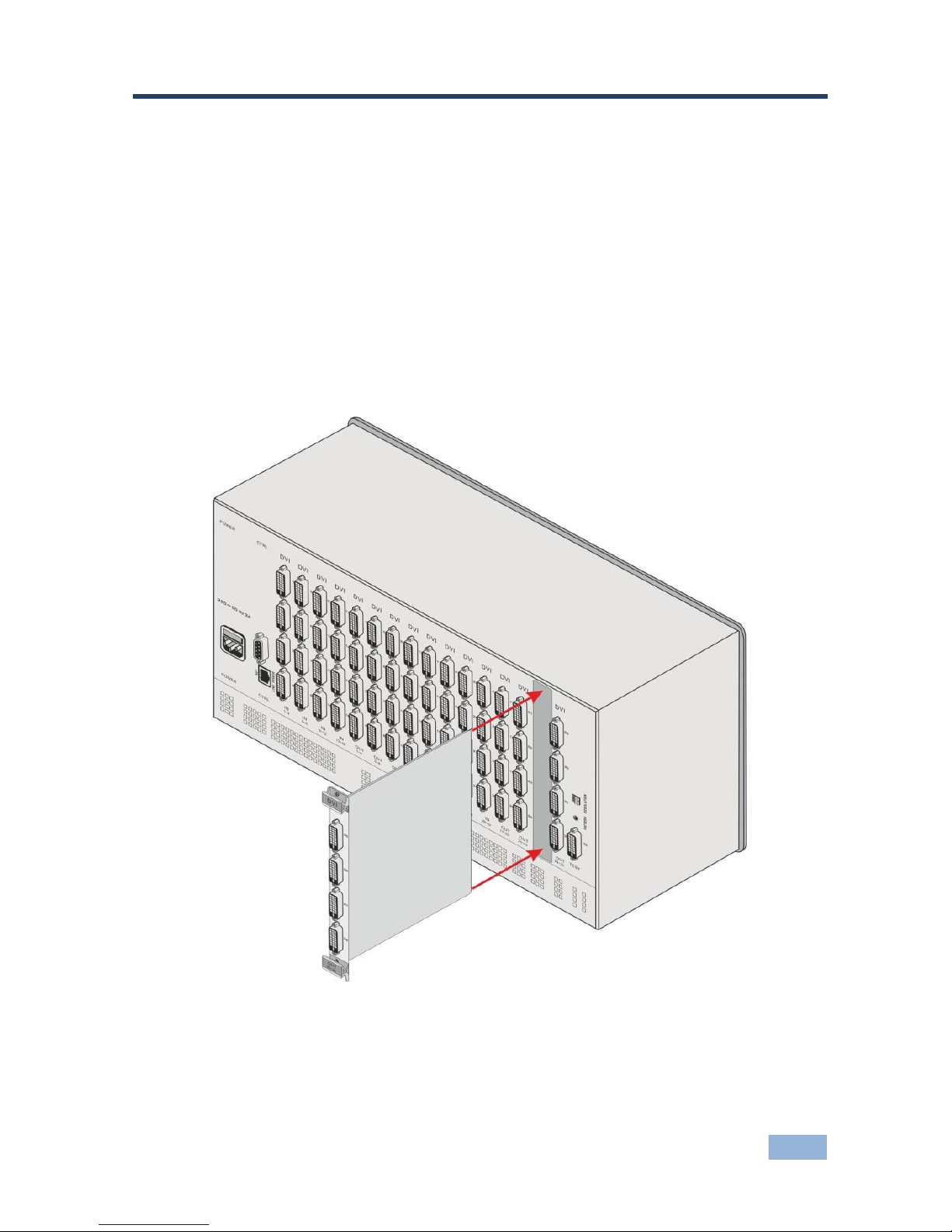
VS-1616D-MD - Hardware Installation Instructions
67
11 Hardware Installation Instructions
11.1 I/O Card Installation
The VS-1616D-MD I/O cards mount in one of the 16 slots on the rear of the
VS-1616D-MD chassis. Slots are numbered from left to right and must be filled
consecutively from left to right, without leaving empty slots.
WARNING: An input card must only be mounted in a slot designated for input
cards (slots IN 1 to 4 and IN 9 to 12) and an output card must only be mounted in
a slot designated for output cards (slots OUT 5 to 8 and OUT 13 to 16).
Figure 16: Inserting the Card into a Slot
Page 73
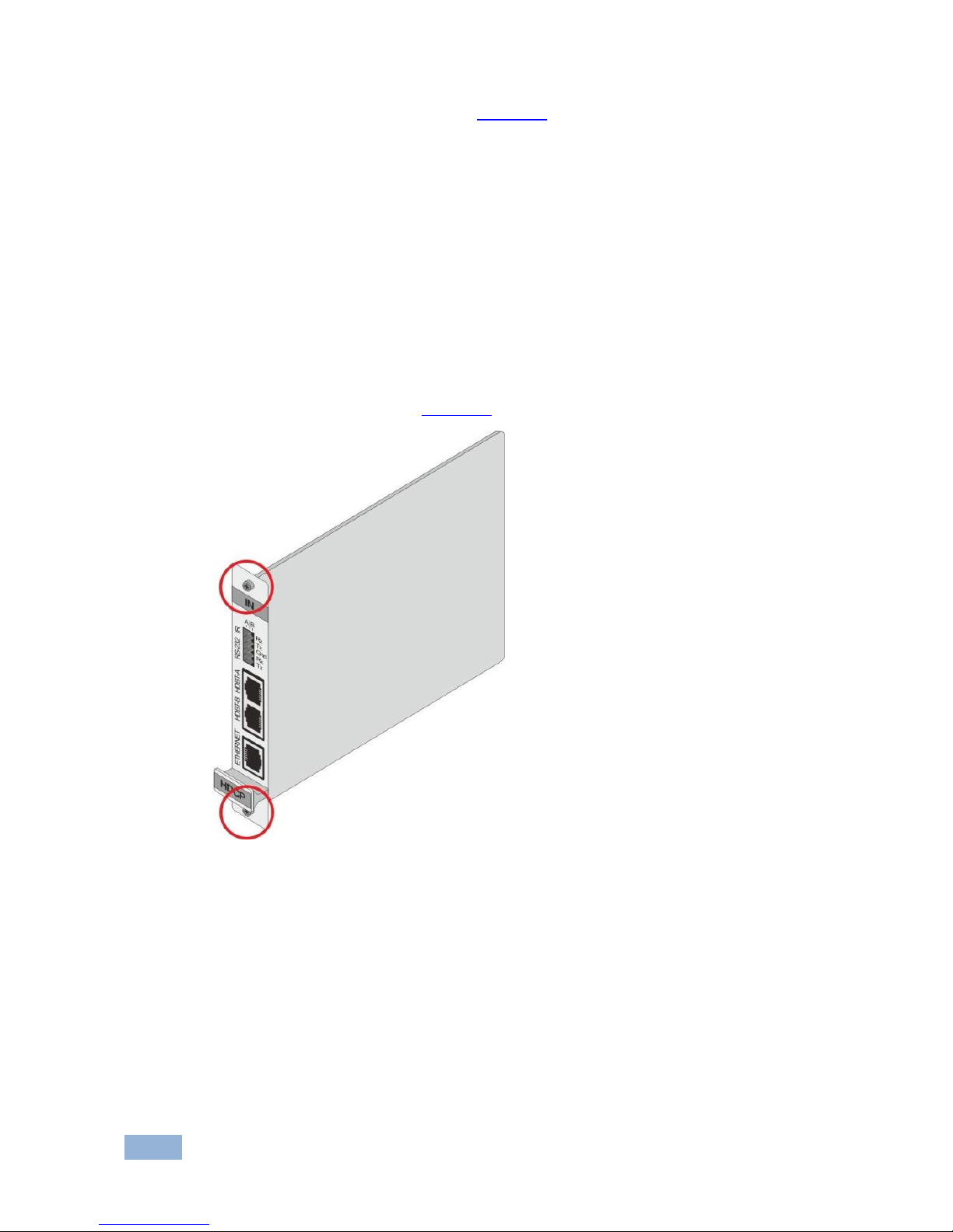
68
VS-1616D-MD - Hardware Installation Instructions
To install an I/O card as shown in Figure 16:
1. Power off the VS-1616D-MD and all devices connected to it.
2. Using a Phillips screwdriver, loosen the screws at the top and bottom of the
blanking plate.
3. Remove the blanking plate from the slot and store it for possible future use.
4. Remove the new card from its shipping box and anti-ESD bag.
5. Holding the card by the upper and lower handle, align the card with the
plastic guide rails (see Figure 17).
Figure 17: Card Handles
6. Slide the card into the chassis until the front of the card makes contact with
the connector inside the chassis.
7. Press the card firmly into the slot until the connector plate is flush with the
rear panel of the chassis and the connector is fully seated.
8. Using a Phillips screwdriver, tighten the retaining screws at the top and
bottom of the card to secure it to the chassis.
Page 74

VS-1616D-MD - Hardware Installation Instructions
69
9. Power on the VS-1616D-MD and follow the procedure to configure the new
card (see Section 9).
10. Power on the peripheral devices.
Page 75

70
VS-1616D-MD - Upgrading the VS-1616D-MD Firmware
12 Upgrading the VS-1616D-MD Firmware
Upgrading the firmware on the VS-1616D-MD can only be done by authorized
service personnel.
Page 76

VS-1616D-MD - Technical Specifications
71
13 Technical Specifications
BANDWIDTH:
Supports up to 3.2Gbps bandwidth per channel (limited
by the cards installed)
MAX RESOLUTION:
Up to UXGA; 1080p
CONTROLS:
Front panel buttons, Infrared remote control transmitter,
RS-232, Ethernet
SWITCHING:
Confirm or At Once for immediate switching
POWER CONSUMPTION:
100-240V AC, 50/60Hz, 135VA
OPERATING TEMPERATURE:
0° to +50°C (32° to 122°F)
STORAGE TEMPERATURE:
–45° to +72°C (–49° to 162°F)
HUMIDITY:
10% to 90%, RHL non-condensing
COOLING:
Forced air, fan
ENCLOSURE TYPE:
Aluminium
RACK MOUNT:
With supplied rack “ears”
DIMENSIONS:
19” 4U (47.5cm x 37cm x 18cm W, D, H)
PRODUCT WEIGHT:
7.45kg (16.42lbs) approx.
SHIPPING WEIGHT:
8.75kg (19.29lbs) approx.
VIBRATION:
ISTA 1A in carton (International Safe Transit
Association)
SAFETY REGULATORY
COMPLIANCE:
CE, FCC
MTBF:
10 years
ENVIRONMENTAL
REGULATORY COMPLIANCE:
Complies with appropriate requirements of RoHs and
WEEE
INCLUDED ACCESSORIES:
Power cord, Infrared remote control transmitter
Specifications are subject to change without notice at http://www.kramerelectronics.com
The following table lists the technical specifications of the cards that are
compatible with the VS-1616D-MD chassis.
Page 77
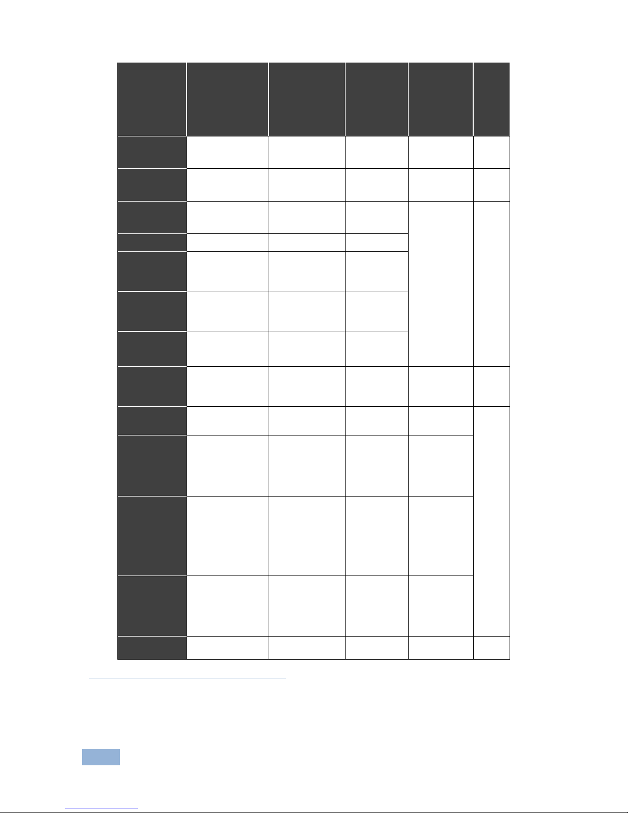
72
VS-1616D-MD - Technical Specifications
Card
Ports
Bandwidth
per Channel
Total
Bandwidth
Compliance
3D Pass
Through
DVI
2 DVI-D on a DVI
Molex 24-pin (F)
connector
1.65Gbps
4.955Gbps
DVI 1.0
DVI Dual
Channel
1 DVI-D on a DVI
Molex 24-pin (F)
connector
3.3Gbps
9.9Gbps
DVI 1.0
HDCP
2 DVI-D on a DVI
Molex 24-pin (F)
connector
2.25Gbps
6.75Gbps
HDCP/HDMI
Yes
HDMI
2 HDMI
2.25Gbps
6.75Gbps
HDMI plus
Digital
Audio
2 HDMI
2 Digital audio on an
RCA connector
2.25Gbps
6.75Gbps
HDMI plus
Analog
Audio
2 HDMI
2 Analog audio on
3.5mm mini jacks
2.25Gbps
6.75Gbps
HDMI
(SC Fiber
Optic)
2 SC
2.25Gbps
6.75Gbps
DVI (4LC
Fiber
Optic1)
2 4 LC
1.65Gbps
4.95Gbps
DVI 1.0
HDMI
(F-6702)
2 SC
2.25Gbps
6.75Gbps
HDCP/HDMI
Yes
DGKat3
plus RS232
2 TP DGKat ports
on RJ-45
2 Serial ports on 3pin terminal blocks
Video: 1.65Gbps
Serial Data: 19200
Video:
4.95Gbps
(See note
below table)
Serial Data:
19200
HDCP/HDMI
HDBaseT4
2 HDBaseT TP on
RJ45 connectors
2 RS-232 Serial
ports and 2 IR ports
on a 10-pin terminal
block
1 Ethernet port on
an RJ-45 connector
Video: 2.25Gbps
Serial Data:
115200
Video:
6.75Gbps
Serial Data:
115200
HDCP/HDMI/
HDBaseT
HDBaseT
Lite
2 HDBaseT TP on
RJ45 connectors
2 RS-232 Serial
ports and 2 IR ports
on a 10-pin terminal
block
Video: 2.97Gbps
Serial Data:
115200
Video:
8.91Gbps
Serial Data:
115200
HDCP/HDMI/
HDBaseT
VGA
2 VGA on 15-pin HD
connectors
1
Multi-mode glass fiber cables with LC connections must be used, such as the Kramer C-4LC/4LC
2
Multi-mode glass fiber cables with SC connections must be used, such as the Kramer C-SC/SC/OM3
3
Twisted pair cables with RJ-45 connections must be used, such as the Kramer BC-DGKat623
4
Twisted pair cables with RJ-45 connections must be used, such as the Kramer BC-HDKat6a
Page 78

VS-1616D-MD - Technical Specifications
73
Note: DGKat cards support Deep Color only at resolutions of 720p and lower.
For the DVI 4LC, multi-mode glass fiber cables with LC connections must be used,
such as the Kramer C-4LC/4LC.
For the DVI SC, Multi-mode glass fiber cables with SC connections must be used,
such as the Kramer C-SC/SC/OM3.
For the DGKat plus RS-232, shielded TP pair cables with RJ-45 connections must
be used, such as the Kramer BC-DGKat623 or BC-DGKat7a23.
For the HDBaseT, twisted pair cables with RJ-45 connections must be used, such
as the Kramer BC-HDKat6a.
Page 79
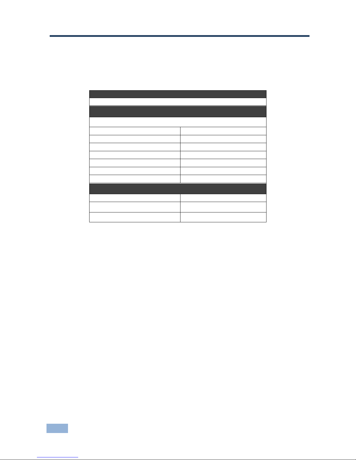
74
VS-1616D-MD - Default Communication Parameters
14 Default Communication Parameters
The following table lists the default communication parameters for the
VS-1616D-MD.
EDID
EDID data is passed between Output 1 and Input 1
RS-232
Protocol 2000/3000
Baud Rate:
9600
Data Bits:
8
Stop Bits:
1
Parity:
None
Command Format:
HEX
P2000, to switch Output 1 to Input 1:
0x01, 0x81, 0x81, 0x81
P3000, to switch Output 1 to Input 4:
#AV 4>1
Ethernet
IP Address
192.168.1.39
TCP Port #
5000
UDP Port #
50000
Page 80
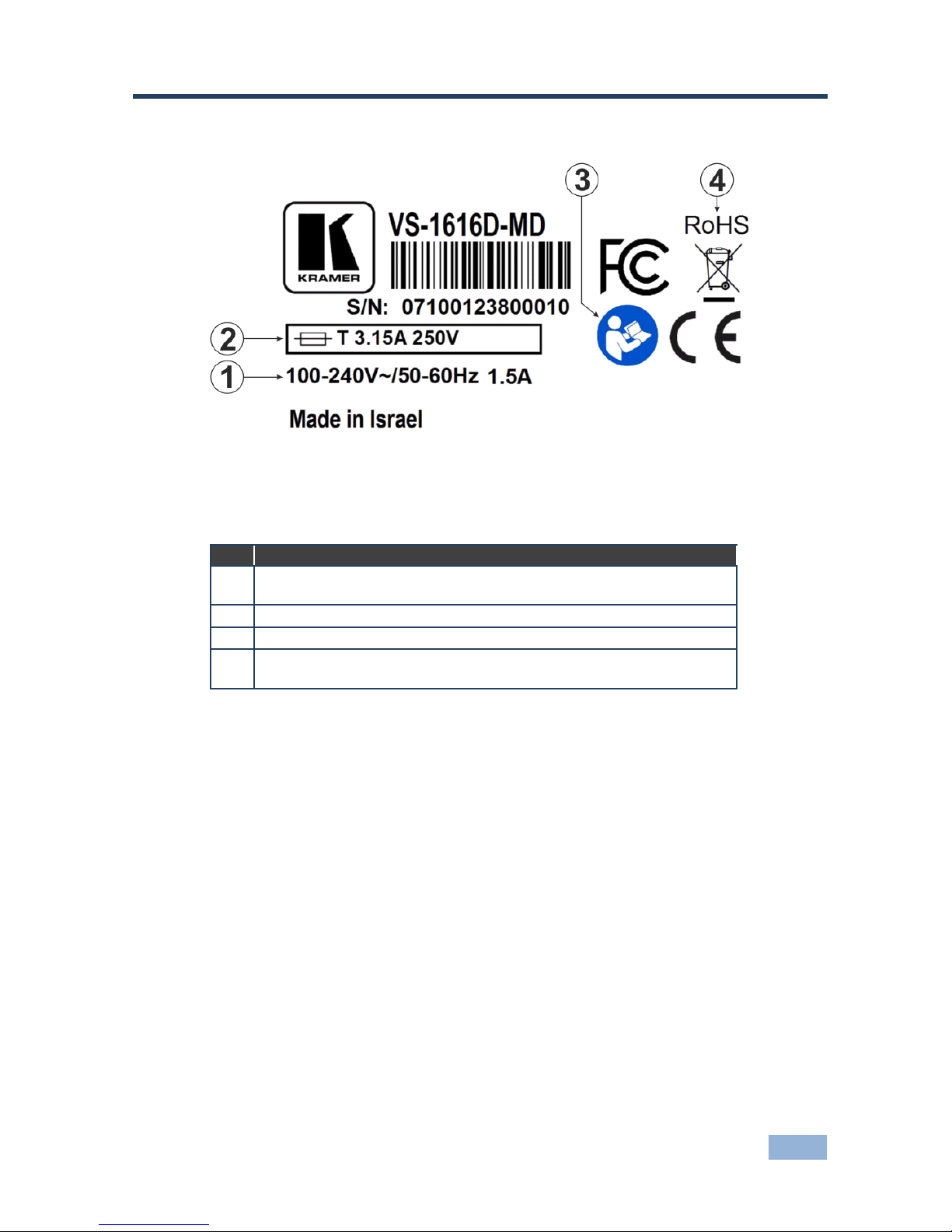
VS-1616D-MD - Label Information
75
15 Label Information
Figure 18: Device Label
Descriptions of the symbols are shown in the table below.
#
Description
1
Device power requirement—between 100 and 240V AC either 50 or
60Hz at 1.5A
2
Fuse—Rating 250V at 3.15A time lag
3
Important information included in the User Manual
4
Complies with the WEEE Restriction of Hazardous Substances
Directive of the EU of 2006 for devices placed on the market after 2005
Page 81

76
VS-1616D-MD - Factory Default EDID
16 Factory Default EDID
16.1 DVI Input Card
Monitor
Model name............... VS-16DVIS
Manufacturer............. KMR
Plug and Play ID......... KMR0200
Serial number............ 1
Manufacture date......... 2006, ISO week 12
-------------------------
EDID revision............ 1.3
Input signal type........ Digital (DVI)
Color bit depth.......... Undefined
Display type............. RGB color
Screen size.............. 700 x 390 mm (31.5 in)
Power management......... Not supported
Extension blocs.......... None
-------------------------
DDC/CI................... n/a
Color characteristics
Default color space...... Non-sRGB
Display gamma............ 2.20
Red chromaticity......... Rx 0.640 - Ry 0.341
Green chromaticity....... Gx 0.286 - Gy 0.610
Blue chromaticity........ Bx 0.146 - By 0.069
White point (default).... Wx 0.284 - Wy 0.293
Additional descriptors... None
Timing characteristics
Horizontal scan range.... 31-94kHz
Vertical scan range...... 50-85Hz
Video bandwidth.......... 170MHz
CVT standard............. Not supported
GTF standard............. Not supported
Additional descriptors... None
Preferred timing......... Yes
Native/preferred timing.. 1280x768p at 60Hz (4:3)
Modeline............... "1280x768" 79.500 1280 1344 1472 1664 768 771 778 798 +hsync +vsync
Detailed timing #1....... 1920x1200p at 60Hz (16:10)
Modeline............... "1920x1200" 154.000 1920 1968 2000 2080 1200 1203 1209 1235 +hsync -vsync
Standard timings supported
720 x 400p at 70Hz - IBM VGA
720 x 400p at 88Hz - IBM XGA2
640 x 480p at 60Hz - IBM VGA
640 x 480p at 67Hz - Apple Mac II
640 x 480p at 72Hz - VESA
640 x 480p at 75Hz - VESA
800 x 600p at 56Hz - VESA
800 x 600p at 60Hz - VESA
800 x 600p at 72Hz - VESA
800 x 600p at 75Hz - VESA
832 x 624p at 75Hz - Apple Mac II
1024 x 768i at 87Hz - IBM
1024 x 768p at 60Hz - VESA
1024 x 768p at 70Hz - VESA
1024 x 768p at 75Hz - VESA
1280 x 1024p at 75Hz - VESA
1152 x 870p at 75Hz - Apple Mac II
1360 x 765p at 60Hz - VESA STD
1280 x 800p at 60Hz - VESA STD
1440 x 900p at 60Hz - VESA STD
1280 x 960p at 60Hz - VESA STD
1280 x 1024p at 60Hz - VESA STD
1400 x 1050p at 60Hz - VESA STD
1680 x 1050p at 60Hz - VESA STD
1600 x 1200p at 60Hz - VESA STD
Page 82

VS-1616D-MD - Factory Default EDID
77
Raw data
00,FF,FF,FF,FF,FF,FF,00,2E,4D,00,02,01,00,00,00,0C,10,01,03,81,46,27,78,0A,D5,7C,A3,57,49,9C,25,11,48,4B,
FF,FF,80,8B,C0,81,00,95,00,81,40,81,80,90,40,B3,00,A9,40,0E,1F,00,80,51,00,1E,30,40,80,
37,00,6F,13,11,00,00,1E,28,3C,80,A0, 70,B0,23,40, 30,20, 36, 00,06,44,21,00,00,1A,00,00,00,FC,00,56,
53,2D,33,32,44,56,49,53,0A,20,20,20,00,00, 00,FD,00,32,55,1F,5E,11,00,0A, 20,20,20, 20, 20,20,00,39
16.2 HDCP Input Card
Monitor
Model name............... VS-16HDCP
Manufacturer............. KMR
Plug and Play ID......... KMR0200
Serial number............ 1
Manufacture date......... 2010, ISO week 24
-------------------------
EDID revision............ 1.3
Input signal type........ Digital (DVI)
Color bit depth.......... Undefined
Display type............. RGB color
Screen size.............. 700 x 390 mm (31.5 in)
Power management......... Not supported
Extension blocs.......... 1 (CEA-EXT)
-------------------------
DDC/CI................... n/a
Color characteristics
Default color space...... Non-sRGB
Display gamma............ 2.20
Red chromaticity......... Rx 0.640 - Ry 0.341
Green chromaticity....... Gx 0.286 - Gy 0.610
Blue chromaticity........ Bx 0.146 - By 0.069
White point (default).... Wx 0.284 - Wy 0.293
Additional descriptors... None
Timing characteristics
Horizontal scan range.... 31-94kHz
Vertical scan range...... 50-85Hz
Video bandwidth.......... 170MHz
CVT standard............. Not supported
GTF standard............. Not supported
Additional descriptors... None
Preferred timing......... Yes
Native/preferred timing.. 1920x1080p at 60Hz (16:9)
Modeline............... "1920x1080" 148.500 1920 2008 2052 2200 1080 1084 1089 1125 +hsync +vsync
Detailed timing #1....... 1920x1200p at 60Hz (16:10)
Modeline............... "1920x1200" 154.000 1920 1968 2000 2080 1200 1203 1209 1235 +hsync -vsync
Standard timings supported
720 x 400p at 70Hz - IBM VGA
720 x 400p at 88Hz - IBM XGA2
640 x 480p at 60Hz - IBM VGA
640 x 480p at 67Hz - Apple Mac II
640 x 480p at 72Hz - VESA
640 x 480p at 75Hz - VESA
800 x 600p at 56Hz - VESA
800 x 600p at 60Hz - VESA
800 x 600p at 72Hz - VESA
800 x 600p at 75Hz - VESA
832 x 624p at 75Hz - Apple Mac II
1024 x 768i at 87Hz - IBM
1024 x 768p at 60Hz - VESA
1024 x 768p at 70Hz - VESA
1024 x 768p at 75Hz - VESA
1280 x 1024p at 75Hz - VESA
1152 x 870p at 75Hz - Apple Mac II
1280 x 720p at 60Hz - VESA STD
1280 x 800p at 60Hz - VESA STD
1440 x 900p at 60Hz - VESA STD
1280 x 960p at 60Hz - VESA STD
1280 x 1024p at 60Hz - VESA STD
1400 x 1050p at 60Hz - VESA STD
Page 83

78
VS-1616D-MD - Factory Default EDID
1680 x 1050p at 60Hz - VESA STD
1600 x 1200p at 60Hz - VESA STD
EIA/CEA-861 Information
Revision number.......... 3
IT underscan............. Not supported
Basic audio.............. Supported
YCbCr 4:4:4.............. Not supported
YCbCr 4:2:2.............. Not supported
Native formats........... 1
Detailed timing #1....... 720x480p at 60Hz (4:3)
Modeline............... "720x480" 27.000 720 736 798 858 480 489 495 525 -hsync -vsync
Detailed timing #2....... 1920x1080i at 60Hz (16:9)
Modeline............... "1920x1080" 74.250 1920 2008 2052 2200 1080 1084 1094 1124 interlace +hsync +vsync
Detailed timing #3....... 1920x1080i at 50Hz (16:9)
Modeline............... "1920x1080" 74.250 1920 2448 2492 2640 1080 1084 1094 1124 interlace +hsync +vsync
Detailed timing #4....... 1280x720p at 60Hz (16:9)
Modeline............... "1280x720" 74.250 1280 1390 1430 1650 720 725 730 750 +hsync +vsync
Detailed timing #5....... 1280x720p at 50Hz (16:9)
Modeline............... "1280x720" 74.250 1280 1720 1760 1980 720 725 730 750 +hsync +vsync
CE video identifiers (VICs) - timing/formats supported
720 x 576p at 50Hz - EDTV (4:3, 16:15)
1280 x 720p at 50Hz - HDTV (16:9, 1:1)
1920 x 1080i at 60Hz - HDTV (16:9, 1:1)
1920 x 1080i at 50Hz - HDTV (16:9, 1:1)
1280 x 720p at 60Hz - HDTV (16:9, 1:1) [Native]
1920 x 1080p at 60Hz - HDTV (16:9, 1:1)
1920 x 1080p at 50Hz - HDTV (16:9, 1:1)
NB: NTSC refresh rate = (Hz*1000)/1001
CE audio data (formats supported)
LPCM 3-channel, 24-bits at 44/48 kHz
CE speaker allocation data
Channel configuration.... 3.0
Front left/right......... Yes
Front LFE................ No
Front center............. Yes
Rear left/right.......... No
Rear center.............. No
Front left/right center.. No
Rear left/right center... No
Rear LFE................. No
CE vendor specific data (VSDB)
IEEE registration number. 0x000C03
CEC physical address..... 1.0.0.0
Maximum TMDS clock....... 165MHz
Raw data
00,FF,FF,FF,FF,FF,FF,00,2E,4D,00,02,01,00,00,00,18,14,01,03,81,46,27,78,0A,D5,7C,A3,57,49,9C,25,
11,48,4B,FF,FF,80,81,C0,81,00,95,00,81,40,81,80,90,40,B3,00,A9,40,02,3A,80,18,71,38,2D,40,58,2C,
45,00,C4,8E,21,00,00,1E,28,3C,80,A0,70,B0,23,40,30,20,36,00,06,44,21,00,00,1A,00,00,00,FC,00,56,
53,2D,33,32,48,44,43,50,0A,20,20,20,00,00,00,FD,00,32,55,1F,5E,11,00,0A,20,20,20,20,20,20,01,F9,
02,03,1A,41,47,11,13,05,14,84,10,1F,23,0A,06,04,83,05,00,00,65,03,0C,00,10,00,8C,0A,D0,8A,20,E0,
2D,10,10,3E,96,00,58,C2,21,00,00,18,01,1D,80,18,71,1C,16,20,58,2C,25,00,C4,8E,21,00,00,9E,01,1D,
80,D0,72,1C,16,20,10,2C,25,80,C4,8E,21,00,00,9E,01,1D,00,72,51,D0,1E,20,6E,28,55,00,C4,8E,21,00,
00,1E,01,1D,00,BC,52,D0,1E,20,B8,28,55,40,C4,8E,21,00,00,1E,00,00,00,00,00,00,00,00,00,00,00,C0
Page 84

VS-1616D-MD - Factory Default EDID
79
16.3 HDMI Input Card
Monitor
Model name............... VS-16HDCP
Manufacturer............. KMR
Plug and Play ID......... KMR0200
Serial number............ 1
Manufacture date......... 2006, ISO week 12
-------------------------
EDID revision............ 1.3
Input signal type........ Digital (DVI)
Color bit depth.......... Undefined
Display type............. RGB color
Screen size.............. 700 x 390 mm (31.5 in)
Power management......... Not supported
Extension blocs.......... 1 (CEA-EXT)
-------------------------
DDC/CI................... n/a
Color characteristics
Default color space...... Non-sRGB
Display gamma............ 2.20
Red chromaticity......... Rx 0.640 - Ry 0.341
Green chromaticity....... Gx 0.286 - Gy 0.610
Blue chromaticity........ Bx 0.146 - By 0.069
White point (default).... Wx 0.284 - Wy 0.293
Additional descriptors... None
Timing characteristics
Horizontal scan range.... 31-94kHz
Vertical scan range...... 50-85Hz
Video bandwidth.......... 170MHz
CVT standard............. Not supported
GTF standard............. Not supported
Additional descriptors... None
Preferred timing......... Yes
Native/preferred timing.. 1280x768p at 60Hz (4:3)
Modeline............... "1280x768" 79.500 1280 1344 1472 1664 768 771 778 798 +hsync +vsync
Detailed timing #1....... 1920x1200p at 60Hz (16:10)
Modeline............... "1920x1200" 154.000 1920 1968 2000 2080 1200 1203 1209 1235 +hsync -vsync
Standard timings supported
720 x 400p at 70Hz - IBM VGA
720 x 400p at 88Hz - IBM XGA2
640 x 480p at 60Hz - IBM VGA
640 x 480p at 67Hz - Apple Mac II
640 x 480p at 72Hz - VESA
640 x 480p at 75Hz - VESA
800 x 600p at 56Hz - VESA
800 x 600p at 60Hz - VESA
800 x 600p at 72Hz - VESA
800 x 600p at 75Hz - VESA
832 x 624p at 75Hz - Apple Mac II
1024 x 768i at 87Hz - IBM
1024 x 768p at 60Hz - VESA
1024 x 768p at 70Hz - VESA
1024 x 768p at 75Hz - VESA
1280 x 1024p at 75Hz - VESA
1152 x 870p at 75Hz - Apple Mac II
1360 x 765p at 60Hz - VESA STD
1280 x 800p at 60Hz - VESA STD
1440 x 900p at 60Hz - VESA STD
1280 x 960p at 60Hz - VESA STD
1280 x 1024p at 60Hz - VESA STD
1400 x 1050p at 60Hz - VESA STD
1680 x 1050p at 60Hz - VESA STD
1600 x 1200p at 60Hz - VESA STD
EIA/CEA-861 Information
Revision number.......... 3
IT underscan............. Not supported
Basic audio.............. Supported
Page 85

80
VS-1616D-MD - Factory Default EDID
YCbCr 4:4:4.............. Not supported
YCbCr 4:2:2.............. Not supported
Native formats........... 1
Detailed timing #1....... 720x480p at 60Hz (4:3)
Modeline............... "720x480" 27.000 720 736 798 858 480 489 495 525 -hsync -vsync
Detailed timing #2....... 1920x1080i at 60Hz (16:9)
Modeline............... "1920x1080" 74.250 1920 2008 2052 2200 1080 1084 1094 1124 interlace +hsync +vsync
Detailed timing #3....... 1920x1080i at 50Hz (16:9)
Modeline............... "1920x1080" 74.250 1920 2448 2492 2640 1080 1084 1094 1124 interlace +hsync +vsync
Detailed timing #4....... 1280x720p at 60Hz (16:9)
Modeline............... "1280x720" 74.250 1280 1390 1430 1650 720 725 730 750 +hsync +vsync
Detailed timing #5....... 1280x720p at 50Hz (16:9)
Modeline............... "1280x720" 74.250 1280 1720 1760 1980 720 725 730 750 +hsync +vsync
CE video identifiers (VICs) - timing/formats supported
720 x 576p at 50Hz - EDTV (4:3, 16:15)
1280 x 720p at 50Hz - HDTV (16:9, 1:1)
1920 x 1080i at 60Hz - HDTV (16:9, 1:1)
1920 x 1080i at 50Hz - HDTV (16:9, 1:1)
1280 x 720p at 60Hz - HDTV (16:9, 1:1) [Native]
1920 x 1080p at 60Hz - HDTV (16:9, 1:1)
1920 x 1080p at 50Hz - HDTV (16:9, 1:1)
NB: NTSC refresh rate = (Hz*1000)/1001
CE audio data (formats supported)
LPCM 3-channel, 24-bits at 44/48 kHz
CE speaker allocation data
Channel configuration.... 3.0
Front left/right......... Yes
Front LFE................ No
Front center............. Yes
Rear left/right.......... No
Rear center.............. No
Front left/right center.. No
Rear left/right center... No
Rear LFE................. No
CE vendor specific data (VSDB)
IEEE registration number. 0x000C03
CEC physical address..... 1.0.0.0
Maximum TMDS clock....... 165MHz
Raw data
00,FF,FF,FF,FF,FF,FF,00,2E,4D,00,02,01,00,00,00,0C,10,01,03,81,46,27,78,0A,D5,7C,A3,57,49,9C,25,
11,48,4B,FF,FF,80,8B,C0,81,00,95,00,81,40,81,80,90,40,B3,00,A9,40,0E,1F,00,80,51,00,1E,30,40,80,
37,00,6F,13,11,00,00,1E,28,3C,80,A0,70,B0,23,40,30,20,36,00,06,44,21,00,00,1A,00,00,00,FC,00,56,
53,2D,31,36,48,44,43,50,0A,20,20,20,00,00,00,FD,00,32,55,1F,5E,11,00,0A,20,20,20,20,20,20,01,4D,
02,03,1A,41,47,11,13,05,14,84,10,1F,23,0A,06,04,83,05,00,00,65,03,0C,00,10,00,8C,0A,D0,8A,20,E0,
2D,10,10,3E,96,00,58,C2,21,00,00,18,01,1D,80,18,71,1C,16,20,58,2C,25,00,C4,8E,21,00,00,9E,01,1D,
80,D0,72,1C,16,20,10,2C,25,80,C4,8E,21,00,00,9E,01,1D,00,72,51,D0,1E,20,6E,28,55,00,C4,8E,21,00,
00,1E,01,1D,00,BC,52,D0,1E,20,B8,28,55,40,C4,8E,21,00,00,1E,00,00,00,00,00,00,00,00,00,00,00,C0
Model name............... VS-16HDCP
Manufacturer............. KRM
Plug and Play ID......... KRM0200
Serial number............ 1
Manufacture date......... 2010, ISO week 24
Page 86

VS-1616D-MD - Factory Default EDID
81
16.4 HDMI plus Audio Input Card
Monitor
Model name............... VS-16H+AUD
Manufacturer............. KMR
Plug and Play ID......... KMR0200
Serial number............ 1
Manufacture date......... 2012, ISO week 12
Filter driver............ None
-------------------------
EDID revision............ 1.3
Input signal type........ Digital (DVI)
Color bit depth.......... Undefined
Display type............. RGB color
Screen size.............. 700 x 390 mm (31.5 in)
Power management......... Not supported
Extension blocs.......... 1 (CEA-EXT)
-------------------------
DDC/CI................... Not supported
Color characteristics
Default color space...... Non-sRGB
Display gamma............ 2.20
Red chromaticity......... Rx 0.640 - Ry 0.341
Green chromaticity....... Gx 0.286 - Gy 0.610
Blue chromaticity........ Bx 0.146 - By 0.069
White point (default).... Wx 0.284 - Wy 0.293
Additional descriptors... None
Timing characteristics
Horizontal scan range.... 31-94kHz
Vertical scan range...... 50-85Hz
Video bandwidth.......... 170MHz
CVT standard............. Not supported
GTF standard............. Not supported
Additional descriptors... None
Preferred timing......... Yes
Native/preferred timing.. 1280x720p at 60Hz (4:3)
Modeline............... "1280x720" 74.250 1280 1390 1430 1650 720 725 730 746 +hsync +vsync
Detailed timing #1....... 1920x1080p at 60Hz (16:10)
Modeline............... "1920x1080" 148.500 1920 2008 2052 2200 1080 1084 1089 1125 +hsync -vsync
Standard timings supported
720 x 400p at 70Hz - IBM VGA
720 x 400p at 88Hz - IBM XGA2
640 x 480p at 60Hz - IBM VGA
640 x 480p at 67Hz - Apple Mac II
640 x 480p at 72Hz - VESA
640 x 480p at 75Hz - VESA
800 x 600p at 56Hz - VESA
800 x 600p at 60Hz - VESA
800 x 600p at 72Hz - VESA
800 x 600p at 75Hz - VESA
832 x 624p at 75Hz - Apple Mac II
1024 x 768i at 87Hz - IBM
1024 x 768p at 60Hz - VESA
1024 x 768p at 70Hz - VESA
1024 x 768p at 75Hz - VESA
1280 x 1024p at 75Hz - VESA
1152 x 870p at 75Hz - Apple Mac II
1360 x 765p at 60Hz - VESA STD
1280 x 800p at 60Hz - VESA STD
1440 x 900p at 60Hz - VESA STD
1280 x 960p at 60Hz - VESA STD
1280 x 1024p at 60Hz - VESA STD
1400 x 1050p at 60Hz - VESA STD
1680 x 1050p at 60Hz - VESA STD
1600 x 1200p at 60Hz - VESA STD
EIA/CEA-861 Information
Revision number.......... 3
IT underscan............. Not supported
Page 87

82
VS-1616D-MD - Factory Default EDID
Basic audio.............. Supported
YCbCr 4:4:4.............. Supported
YCbCr 4:2:2.............. Supported
Native formats........... 1
Detailed timing #1....... 720x480p at 60Hz (4:3)
Modeline............... "720x480" 27.000 720 736 798 858 480 489 495 525 -hsync -vsync
Detailed timing #2....... 1920x1080i at 60Hz (16:9)
Modeline............... "1920x1080" 74.250 1920 2008 2052 2200 1080 1084 1094 1124 interlace +hsync +vsync
Detailed timing #3....... 1920x1080i at 50Hz (16:9)
Modeline............... "1920x1080" 74.250 1920 2448 2492 2640 1080 1084 1094 1124 interlace +hsync +vsync
Detailed timing #4....... 1280x720p at 60Hz (16:9)
Modeline............... "1280x720" 74.250 1280 1390 1430 1650 720 725 730 750 +hsync +vsync
Detailed timing #5....... 1280x720p at 50Hz (16:9)
Modeline............... "1280x720" 74.250 1280 1720 1760 1980 720 725 730 750 +hsync +vsync
CE video identifiers (VICs) - timing/formats supported
720 x 576p at 50Hz - EDTV (4:3, 16:15)
1280 x 720p at 50Hz - HDTV (16:9, 1:1)
1920 x 1080i at 60Hz - HDTV (16:9, 1:1)
1920 x 1080i at 50Hz - HDTV (16:9, 1:1)
1280 x 720p at 60Hz - HDTV (16:9, 1:1) [Native]
1920 x 1080p at 60Hz - HDTV (16:9, 1:1)
1920 x 1080p at 50Hz - HDTV (16:9, 1:1)
NB: NTSC refresh rate = (Hz*1000)/1001
CE audio data (formats supported)
LPCM 3-channel, 24-bits at 44/48 kHz
CE speaker allocation data
Channel configuration.... 3.0
Front left/right......... Yes
Front LFE................ No
Front center............. Yes
Rear left/right.......... No
Rear center.............. No
Front left/right center.. No
Rear left/right center... No
Rear LFE................. No
CE vendor specific data (VSDB)
IEEE registration number. 0x000C03
CEC physical address..... 1.0.0.0
Maximum TMDS clock....... 165MHz
Report information
Date generated........... 11/10/2013
Software revision........ 2.60.0.972
Data source.............. Real-time 0x0051
Operating system......... 5.1.2600.2.Service Pack 3
Raw data
00,FF,FF,FF,FF,FF,FF,00,2E,4D,00,02,01,00,00,00,0C,16,01,03,81,46,27,78,0A,D5,7C,A3,57,49,9C,25,
11,48,4B,FF,FF,80,8B,C0,81,00,95,00,81,40,81,80,90,40,B3,00,A9,40,01,1D,00,72,51,D0,1A,20,6E,28,
55,00,6F,13,11,00,00,1E,02,3A,80,18,71,38,2D,40,58,2C,45,00,06,44,21,00,00,1A,00,00,00,FC,00,56,
53,2D,31,36,48,2B,41,55,44,0A,20,20,00,00,00,FD,00,32,55,1F,5E,11,00,0A,20,20,20,20,20,20,01,80,
02,03,1A,71,47,11,13,05,14,84,10,1F,23,0A,06,04,83,05,00,00,65,03,0C,00,10,00,8C,0A,D0,8A,20,E0,
2D,10,10,3E,96,00,58,C2,21,00,00,18,01,1D,80,18,71,1C,16,20,58,2C,25,00,C4,8E,21,00,00,9E,01,1D,
80,D0,72,1C,16,20,10,2C,25,80,C4,8E,21,00,00,9E,01,1D,00,72,51,D0,1E,20,6E,28,55,00,C4,8E,21,00,
00,1E,01,1D,00,BC,52,D0,1E,20,B8,28,55,40,C4,8E,21,00,00,1E,00,00,00,00,00,00,00,00,00,00,00,90
Page 88

VS-1616D-MD - Factory Default EDID
83
16.5 DVI Dual Channel Input Card
Monitor
Model name............... VS-16DUAL
Manufacturer............. KMR
Plug and Play ID......... KMR0200
Serial number............ 1
Manufacture date......... 2006, ISO week 12
Filter driver............ None
-------------------------
EDID revision............ 1.3
Input signal type........ Digital (DVI)
Color bit depth.......... Undefined
Display type............. RGB color
Screen size.............. 700 x 390 mm (31.5 in)
Power management......... Not supported
Extension blocs.......... None
-------------------------
DDC/CI................... n/a
Color characteristics
Default color space...... Non-sRGB
Display gamma............ 2.20
Red chromaticity......... Rx 0.640 - Ry 0.341
Green chromaticity....... Gx 0.286 - Gy 0.610
Blue chromaticity........ Bx 0.146 - By 0.069
White point (default).... Wx 0.284 - Wy 0.293
Additional descriptors... None
Timing characteristics
Horizontal scan range.... 31-94kHz
Vertical scan range...... 50-85Hz
Video bandwidth.......... 170MHz
CVT standard............. Not supported
GTF standard............. Not supported
Additional descriptors... None
Preferred timing......... Yes
Native/preferred timing.. 1024x768p at 60Hz (4:3)
Modeline............... "1024x768" 65.000 1024 1048 1184 1344 768 771 777 806 +hsync +vsync
Detailed timing #1....... 1920x1200p at 60Hz (16:10)
Modeline............... "1920x1200" 154.000 1920 1968 2000 2080 1200 1203 1209 1235 +hsync -vsync
Standard timings supported
720 x 400p at 70Hz - IBM VGA
720 x 400p at 88Hz - IBM XGA2
640 x 480p at 60Hz - IBM VGA
640 x 480p at 67Hz - Apple Mac II
640 x 480p at 72Hz - VESA
640 x 480p at 75Hz - VESA
800 x 600p at 56Hz - VESA
800 x 600p at 60Hz - VESA
800 x 600p at 72Hz - VESA
800 x 600p at 75Hz - VESA
832 x 624p at 75Hz - Apple Mac II
1024 x 768i at 87Hz - IBM
1024 x 768p at 60Hz - VESA
1024 x 768p at 70Hz - VESA
1024 x 768p at 75Hz - VESA
1280 x 1024p at 75Hz - VESA
1152 x 870p at 75Hz - Apple Mac II
1360 x 765p at 60Hz - VESA STD
1280 x 800p at 60Hz - VESA STD
1440 x 900p at 60Hz - VESA STD
1280 x 960p at 60Hz - VESA STD
1280 x 1024p at 60Hz - VESA STD
1400 x 1050p at 60Hz - VESA STD
1680 x 1050p at 60Hz - VESA STD
1600 x 1200p at 60Hz - VESA STD
EIA/CEA-861 Information
Revision number.......... 3
IT underscan............. Not supported
Page 89

84
VS-1616D-MD - Factory Default EDID
Basic audio.............. Supported
YCbCr 4:4:4.............. Not supported
YCbCr 4:2:2.............. Not supported
Native formats........... 1
Detailed timing #1....... 720x480p at 60Hz (4:3)
Modeline............... "720x480" 27.000 720 736 798 858 480 489 495 525 -hsync -vsync
Detailed timing #2....... 1920x1080i at 60Hz (16:9)
Modeline............... "1920x1080" 74.250 1920 2008 2052 2200 1080 1084 1094 1124 interlace +hsync +vsync
Detailed timing #3....... 1920x1080i at 50Hz (16:9)
Modeline............... "1920x1080" 74.250 1920 2448 2492 2640 1080 1084 1094 1124 interlace +hsync +vsync
Detailed timing #4....... 1280x720p at 60Hz (16:9)
Modeline............... "1280x720" 74.250 1280 1390 1430 1650 720 725 730 750 +hsync +vsync
Detailed timing #5....... 1280x720p at 50Hz (16:9)
Modeline............... "1280x720" 74.250 1280 1720 1760 1980 720 725 730 750 +hsync +vsync
CE video identifiers (VICs) - timing/formats supported
720 x 576p at 50Hz - EDTV (4:3, 16:15)
1280 x 720p at 50Hz - HDTV (16:9, 1:1)
1920 x 1080i at 60Hz - HDTV (16:9, 1:1)
1920 x 1080i at 50Hz - HDTV (16:9, 1:1)
1280 x 720p at 60Hz - HDTV (16:9, 1:1) [Native]
1920 x 1080p at 60Hz - HDTV (16:9, 1:1)
1920 x 1080p at 50Hz - HDTV (16:9, 1:1)
NB: NTSC refresh rate = (Hz*1000)/1001
CE audio data (formats supported)
LPCM 3-channel, 24-bits at 44/48 kHz
CE speaker allocation data
Channel configuration.... 3.0
Front left/right......... Yes
Front LFE................ No
Front center............. Yes
Rear left/right.......... No
Rear center.............. No
Front left/right center.. No
Rear left/right center... No
Rear LFE................. No
CE vendor specific data (VSDB)
IEEE registration number. 0x000C03
CEC physical address..... 1.0.0.0
Maximum TMDS clock....... 165MHz
Raw data
00,FF,FF,FF,FF,FF,FF,00,2E,4D,00,02,01,00,00,00,0C,10,01,03,81,46,27,78,0A,D5,7C,A3,57,49,9C,25,
11,48,4B,FF,FF,80,8B,C0,81,00,95,00,81,40,81,80,90,40,B3,00,A9,40,64,19,00,40,41,00,26,30,18,88,
36,00,6F,13,11,00,00,1E,28,3C,80,A0,70,B0,23,40,30,20,36,00,06,44,21,00,00,1A,00,00,00,FC,00,56,
53,2D,31,36,44,55,41,4C,0A,20,20,20,00,00,00,FD,00,32,55,1F,5E,11,00,0A,20,20,20,20,20,20,00,60,
02,03,1A,41,47,11,13,05,14,84,10,1F,23,0A,06,04,83,05,00,00,65,03,0C,00,10,00,8C,0A,D0,8A,20,E0,
2D,10,10,3E,96,00,58,C2,21,00,00,18,01,1D,80,18,71,1C,16,20,58,2C,25,00,C4,8E,21,00,00,9E,01,1D,
80,D0,72,1C,16,20,10,2C,25,80,C4,8E,21,00,00,9E,01,1D,00,72,51,D0,1E,20,6E,28,55,00,C4,8E,21,00,
00,1E,01,1D,00,BC,52,D0,1E,20,B8,28,55,40,C4,8E,21,00,00,1E,00,00,00,00,00,00,00,00,00,00,00,C0
Page 90

VS-1616D-MD - Factory Default EDID
85
16.6 DGKat Input Card
Monitor
Model name............... VS-16hCat5e
Manufacturer............. KMR
Plug and Play ID......... KMR0200
Serial number............ 1
Manufacture date......... 2006, ISO week 12
Filter driver............ None
-------------------------
EDID revision............ 1.3
Input signal type........ Digital (DVI)
Color bit depth.......... Undefined
Display type............. RGB color
Screen size.............. 700 x 390 mm (31.5 in)
Power management......... Not supported
Extension blocs.......... 1 (CEA-EXT)
-------------------------
DDC/CI................... n/a
Color characteristics
Default color space...... Non-sRGB
Display gamma............ 2.20
Red chromaticity......... Rx 0.640 - Ry 0.341
Green chromaticity....... Gx 0.286 - Gy 0.610
Blue chromaticity........ Bx 0.146 - By 0.069
White point (default).... Wx 0.284 - Wy 0.293
Additional descriptors... None
Timing characteristics
Horizontal scan range.... 31-94kHz
Vertical scan range...... 50-85Hz
Video bandwidth.......... 170MHz
CVT standard............. Not supported
GTF standard............. Not supported
Additional descriptors... None
Preferred timing......... Yes
Native/preferred timing.. 1280x768p at 60Hz (4:3)
Modeline............... "1280x768" 79.500 1280 1344 1472 1664 768 771 778 798 +hsync +vsync
Detailed timing #1....... 1920x1200p at 60Hz (16:10)
Modeline............... "1920x1200" 154.000 1920 1968 2000 2080 1200 1203 1209 1235 +hsync -vsync
Standard timings supported
720 x 400p at 70Hz - IBM VGA
720 x 400p at 88Hz - IBM XGA2
640 x 480p at 60Hz - IBM VGA
640 x 480p at 67Hz - Apple Mac II
640 x 480p at 72Hz - VESA
640 x 480p at 75Hz - VESA
800 x 600p at 56Hz - VESA
800 x 600p at 60Hz - VESA
800 x 600p at 72Hz - VESA
800 x 600p at 75Hz - VESA
832 x 624p at 75Hz - Apple Mac II
1024 x 768i at 87Hz - IBM
1024 x 768p at 60Hz - VESA
1024 x 768p at 70Hz - VESA
1024 x 768p at 75Hz - VESA
1280 x 1024p at 75Hz - VESA
1152 x 870p at 75Hz - Apple Mac II
1360 x 765p at 60Hz - VESA STD
1280 x 800p at 60Hz - VESA STD
1440 x 900p at 60Hz - VESA STD
1280 x 960p at 60Hz - VESA STD
1280 x 1024p at 60Hz - VESA STD
1400 x 1050p at 60Hz - VESA STD
1680 x 1050p at 60Hz - VESA STD
1600 x 1200p at 60Hz - VESA STD
EIA/CEA-861 Information
Revision number.......... 3
IT underscan............. Not supported
Page 91

86
VS-1616D-MD - Factory Default EDID
Basic audio.............. Supported
YCbCr 4:4:4.............. Not supported
YCbCr 4:2:2.............. Not supported
Native formats........... 1
Detailed timing #1....... 720x480p at 60Hz (4:3)
Modeline............... "720x480" 27.000 720 736 798 858 480 489 495 525 -hsync -vsync
Detailed timing #2....... 1920x1080i at 60Hz (16:9)
Modeline............... "1920x1080" 74.250 1920 2008 2052 2200 1080 1084 1094 1124 interlace +hsync +vsync
Detailed timing #3....... 1920x1080i at 50Hz (16:9)
Modeline............... "1920x1080" 74.250 1920 2448 2492 2640 1080 1084 1094 1124 interlace +hsync +vsync
Detailed timing #4....... 1280x720p at 60Hz (16:9)
Modeline............... "1280x720" 74.250 1280 1390 1430 1650 720 725 730 750 +hsync +vsync
Detailed timing #5....... 1280x720p at 50Hz (16:9)
Modeline............... "1280x720" 74.250 1280 1720 1760 1980 720 725 730 750 +hsync +vsync
CE video identifiers (VICs) - timing/formats supported
720 x 576p at 50Hz - EDTV (4:3, 16:15)
1280 x 720p at 50Hz - HDTV (16:9, 1:1)
1920 x 1080i at 60Hz - HDTV (16:9, 1:1)
1920 x 1080i at 50Hz - HDTV (16:9, 1:1)
1280 x 720p at 60Hz - HDTV (16:9, 1:1) [Native]
1920 x 1080p at 60Hz - HDTV (16:9, 1:1)
1920 x 1080p at 50Hz - HDTV (16:9, 1:1)
NB: NTSC refresh rate = (Hz*1000)/1001
CE audio data (formats supported)
LPCM 3-channel, 24-bits at 44/48 kHz
CE speaker allocation data
Channel configuration.... 3.0
Front left/right......... Yes
Front LFE................ No
Front center............. Yes
Rear left/right.......... No
Rear center.............. No
Front left/right center.. No
Rear left/right center... No
Rear LFE................. No
CE vendor specific data (VSDB)
IEEE registration number. 0x000C03
CEC physical address..... 1.0.0.0
Maximum TMDS clock....... 165MHz
Raw data
00,FF,FF,FF,FF,FF,FF,00,2E,4D,00,02,01,00,00,00,0C,10,01,03,81,46,27,78,0A,D5,7C,A3,57,49,9C,25,
11,48,4B,FF,FF,80,8B,C0,81,00,95,00,81,40,81,80,90,40,B3,00,A9,40,0E,1F,00,80,51,00,1E,30,40,80,
37,00,6F,13,11,00,00,1E,28,3C,80,A0,70,B0,23,40,30,20,36,00,06,44,21,00,00,1A,00,00,00,FC,00,56,
53,2D,31,36,68,43,61,74,35,65,0A,20,00,00,00,FD,00,32,55,1F,5E,11,00,0A,20,20,20,20,20,20,01,92,
02,03,1A,41,47,11,13,05,14,84,10,1F,23,0A,06,04,83,05,00,00,65,03,0C,00,10,00,8C,0A,D0,8A,20,E0,
2D,10,10,3E,96,00,58,C2,21,00,00,18,01,1D,80,18,71,1C,16,20,58,2C,25,00,C4,8E,21,00,00,9E,01,1D,
80,D0,72,1C,16,20,10,2C,25,80,C4,8E,21,00,00,9E,01,1D,00,72,51,D0,1E,20,6E,28,55,00,C4,8E,21,00,
00,1E,01,1D,00,BC,52,D0,1E,20,B8,28,55,40,C4,8E,21,00,00,1E,00,00,00,00,00,00,00,00,00,00,00,C0
Page 92

VS-1616D-MD - Factory Default EDID
87
16.7 HDBaseT Input Card
Monitor
Model name............... VS-16HDBST
Manufacturer............. KMR
Plug and Play ID......... KMR0400
Serial number............ 1
Manufacture date......... 2006, ISO week 12
Filter driver............ None
-------------------------
EDID revision............ 1.3
Input signal type........ Digital (DVI)
Color bit depth.......... Undefined
Display type............. RGB color
Screen size.............. 700 x 390 mm (31.5 in)
Power management......... Not supported
Extension blocs.......... 1 (CEA-EXT)
-------------------------
DDC/CI................... n/a
Color characteristics
Default color space...... Non-sRGB
Display gamma............ 2.20
Red chromaticity......... Rx 0.640 - Ry 0.341
Green chromaticity....... Gx 0.286 - Gy 0.610
Blue chromaticity........ Bx 0.146 - By 0.069
White point (default).... Wx 0.284 - Wy 0.293
Additional descriptors... None
Timing characteristics
Horizontal scan range.... 31-94kHz
Vertical scan range...... 50-85Hz
Video bandwidth.......... 170MHz
CVT standard............. Not supported
GTF standard............. Not supported
Additional descriptors... None
Preferred timing......... Yes
Native/preferred timing.. 1280x720p at 60Hz
Modeline............... "1280x720" 74.250 1280 1390 1430 1650 720 725 730 746 +hsync -vsync
Detailed timing #1....... 1920x1200p at 60Hz (16:10)
Modeline............... "1920x1200" 154.000 1920 1968 2000 2080 1200 1203 1209 1235 +hsync -vsync
Standard timings supported
720 x 400p at 70Hz - IBM VGA
720 x 400p at 88Hz - IBM XGA2
640 x 480p at 60Hz - IBM VGA
640 x 480p at 67Hz - Apple Mac II
640 x 480p at 72Hz - VESA
640 x 480p at 75Hz - VESA
800 x 600p at 56Hz - VESA
800 x 600p at 60Hz - VESA
800 x 600p at 72Hz - VESA
800 x 600p at 75Hz - VESA
832 x 624p at 75Hz - Apple Mac II
1024 x 768i at 87Hz - IBM
1024 x 768p at 60Hz - VESA
1024 x 768p at 70Hz - VESA
1024 x 768p at 75Hz - VESA
1280 x 1024p at 75Hz - VESA
1152 x 870p at 75Hz - Apple Mac II
1360 x 765p at 60Hz - VESA STD
1280 x 800p at 60Hz - VESA STD
1440 x 900p at 60Hz - VESA STD
1280 x 960p at 60Hz - VESA STD
1280 x 1024p at 60Hz - VESA STD
1400 x 1050p at 60Hz - VESA STD
1680 x 1050p at 60Hz - VESA STD
1600 x 1200p at 60Hz - VESA STD
EIA/CEA-861 Information
Revision number.......... 3
IT underscan............. Not supported
Page 93

88
VS-1616D-MD - Factory Default EDID
Basic audio.............. Supported
YCbCr 4:4:4.............. Supported
YCbCr 4:2:2.............. Supported
Native formats........... 1
Detailed timing #1....... 720x480p at 60Hz (4:3)
Modeline............... "720x480" 27.000 720 736 798 858 480 489 495 525 -hsync -vsync
Detailed timing #2....... 1920x1080i at 60Hz (16:9)
Modeline............... "1920x1080" 74.250 1920 2008 2052 2200 1080 1084 1094 1124 interlace +hsync +vsync
Detailed timing #3....... 1920x1080i at 50Hz (16:9)
Modeline............... "1920x1080" 74.250 1920 2448 2492 2640 1080 1084 1094 1124 interlace +hsync +vsync
Detailed timing #4....... 1280x720p at 60Hz (16:9)
Modeline............... "1280x720" 74.250 1280 1390 1430 1650 720 725 730 750 +hsync +vsync
Detailed timing #5....... 1280x720p at 50Hz (16:9)
Modeline............... "1280x720" 74.250 1280 1720 1760 1980 720 725 730 750 +hsync +vsync
CE video identifiers (VICs) - timing/formats supported
720 x 576p at 50Hz - EDTV (4:3, 16:15)
1280 x 720p at 50Hz - HDTV (16:9, 1:1)
1920 x 1080i at 60Hz - HDTV (16:9, 1:1)
1920 x 1080i at 50Hz - HDTV (16:9, 1:1)
1280 x 720p at 60Hz - HDTV (16:9, 1:1) [Native]
1920 x 1080p at 60Hz - HDTV (16:9, 1:1)
1920 x 1080p at 50Hz - HDTV (16:9, 1:1)
NB: NTSC refresh rate = (Hz*1000)/1001
CE audio data (formats supported)
LPCM 3-channel, 24-bits at 44/48 kHz
CE speaker allocation data
Channel configuration.... 3.0
Front left/right......... Yes
Front LFE................ No
Front center............. Yes
Rear left/right.......... No
Rear center.............. No
Front left/right center.. No
Rear left/right center... No
Rear LFE................. No
CE vendor specific data (VSDB)
IEEE registration number. 0x000C03
CEC physical address..... 1.0.0.0
Maximum TMDS clock....... 165MHz
Report information
Date generated........... 14/07/2013
Software revision........ 2.60.0.972
Data source.............. File
Operating system......... 6.1.7601.2.Service Pack 1
Raw data
00,FF,FF,FF,FF,FF,FF,00,2E,4D,00,02,01,00,00,00,0C,10,01,03,81,46,27,78,0A,D5,7C,A3,57,49,9C,25,
11,48,4B,FF,FF,80,8B,C0,81,00,95,00,81,40,81,80,90,40,B3,00,A9,40,01,1D,00,72,51,D0,1A,20,6E,28,
55,00,7E,88,42,00,00,1A,28,3C,80,A0,70,B0,23,40,30,20,36,00,06,44,21,00,00,1A,00,00,00,FC,00,56,
53,2D,31,36,48,44,42,53,54,0A,20,20,00,00,00,FD,00,32,55,1F,5E,11,00,0A,20,20,20,20,20,20,01,D3,
02,03,1A,71,47,11,13,05,14,84,10,1F,23,0A,06,04,83,05,00,00,65,03,0C,00,10,00,8C,0A,D0,8A,20,E0,
2D,10,10,3E,96,00,58,C2,21,00,00,18,01,1D,80,18,71,1C,16,20,58,2C,25,00,C4,8E,21,00,00,9E,01,1D,
80,D0,72,1C,16,20,10,2C,25,80,C4,8E,21,00,00,9E,01,1D,00,72,51,D0,1E,20,6E,28,55,00,C4,8E,21,00,
00,1E,01,1D,00,BC,52,D0,1E,20,B8,28,55,40,C4,8E,21,00,00,1E,00,00,00,00,00,00,00,00,00,00,00,90
Page 94

VS-1616D-MD - Factory Default EDID
89
16.8 VGA Input Card
Monitor
Model name............... VGA-IN2-F16
Manufacturer............. KMR
Plug and Play ID......... KMR040B
Serial number............ 17056
Manufacture date......... 2011, ISO week 48
Filter driver............ None
-------------------------
EDID revision............ 1.3
Input signal type........ Analog 0.700,0.300 (1.0V p-p)
Sync input support....... Not available
Display type............. RGB color
Screen size.............. 700 x 390 mm (31.5 in)
Power management......... Not supported
Extension blocs.......... None
-------------------------
DDC/CI................... n/a
Color characteristics
Default color space...... Non-sRGB
Display gamma............ 2.20
Red chromaticity......... Rx 0.640 - Ry 0.341
Green chromaticity....... Gx 0.286 - Gy 0.610
Blue chromaticity........ Bx 0.146 - By 0.069
White point (default).... Wx 0.284 - Wy 0.293
Additional descriptors... None
Timing characteristics
Range limits............. Not available
GTF standard............. Supported
Additional descriptors... None
Preferred timing......... Yes
Native/preferred timing.. 640x480p at 60Hz (4:3)
Modeline............... "640x480" 25.180 640 656 752 800 480 490 492 525 -hsync -vsync
Detailed timing #1....... 1920x1080p at 60Hz (16:9)
Modeline............... "1920x1080" 148.500 1920 2008 2052 2200 1080 1084 1089 1125 +hsync +vsync
Detailed timing #2....... 1600x1200p at 60Hz (4:3)
Modeline............... "1600x1200" 162.000 1600 1664 1856 2160 1200 1201 1204 1250 +hsync +vsync
Standard timings supported
720 x 400p at 70Hz - IBM VGA
720 x 400p at 88Hz - IBM XGA2
640 x 480p at 60Hz - IBM VGA
640 x 480p at 67Hz - Apple Mac II
640 x 480p at 72Hz - VESA
640 x 480p at 75Hz - VESA
800 x 600p at 56Hz - VESA
800 x 600p at 60Hz - VESA
800 x 600p at 72Hz - VESA
800 x 600p at 75Hz - VESA
832 x 624p at 75Hz - Apple Mac II
1024 x 768i at 87Hz - IBM
1024 x 768p at 60Hz - VESA
1024 x 768p at 70Hz - VESA
1024 x 768p at 75Hz - VESA
1280 x 1024p at 75Hz - VESA
1152 x 870p at 75Hz - Apple Mac II
640 x 480p at 60Hz - VESA STD
800 x 600p at 60Hz - VESA STD
1024 x 768p at 60Hz - VESA STD
1152 x 864p at 75Hz - VESA STD
1280 x 1024p at 75Hz - VESA STD
1280 x 960p at 60Hz - VESA STD
1280 x 1024p at 60Hz - VESA STD
1360 x 765p at 60Hz - VESA STD
Page 95

90
VS-1616D-MD - Factory Default EDID
Report information
Date generated........... 14/07/2013
Software revision........ 2.60.0.972
Data source.............. File
Operating system......... 6.1.7601.2.Service Pack 1
Raw data
00,FF,FF,FF,FF,FF,FF,00,2E,4D,0B,04,A0,42,00,00,30,15,01,03,00,46,27,78,0B,D5,7C,A3,57,49,9C,25,
11,48,4B,FF,FF,80,31,40,45,40,61,40,71,4F,81,8F,81,40,81,80,8B,C0,D6,09,80,A0,20,E0,2D,10,10,60,
A2,00,04,03,00,00,00,18,02,3A,80,18,71,38,2D,40,58,2C,45,00,10,09,00,00,00,1E,00,00,00,FC,00,56,
47,41,2D,49,4E,32,2D,46,31,36,0A,20,48,3F,40,30,62,B0,32,40,40,C0,13,00,6F,13,11,00,00,1E,00,0C
Page 96
VS-1616D-MD - Communication Protocol 3000
91
17 Communication Protocol 3000
The VS-1616D-MD can be operated using serial commands from a PC, remote
controller or touch screen using the Kramer Protocol 3000.
This section describes the:
Kramer Protocol 3000 syntax (see Section 17.1)
Kramer Protocol 3000 commands (see Section 17.2)
17.1 Kramer Protocol 3000 Syntax
17.1.1 Host Message Format
Start
Address (optional)
Body
Delimiter
#
device_id@
Message
CR
17.1.2 Simple Command
Command string with only one command without addressing:
Start
Body
Delimiter
#
Command SP Parameter_1,Parameter_2,…
CR
17.1.3 Command String
Formal syntax with commands concatenation and addressing:
Start
Address
Body
Delimiter
#
device_id@
Command_1 Parameter1_1,Parameter1_2,…|
Command_2 Parameter2_1,Parameter2_2,…|
Command_3
Parameter3_1,Parameter3_2,…|…
CR
17.1.4 Device Message Format
Start
Address (optional)
Body
delimiter
~
device_id@
Message
CR LF
17.1.5 Device Long Response
Echoing command:
Start
Address (optional)
Body
Delimiter
~
device_id@
Command SP [Param1 ,Param2 …] result
CR LF
CR = Carriage return (ASCII 13 = 0x0D)
LF = Line feed (ASCII 10 = 0x0A)
Page 97

92
VS-1616D-MD - Communication Protocol 3000
SP = Space (ASCII 32 = 0x20)
17.1.6 Command Terms
Command
A sequence of ASCII letters ('A'-'Z', 'a'-'z' and '-').
Command and parameters must be separated by at least one space.
Parameters
A sequence of alphanumeric ASCII characters ('0'-'9','A'-'Z','a'-'z' and some special
characters for specific commands). Parameters are separated by commas.
Message string
Every command entered as part of a message string begins with a message
starting character and ends with a message closing character.
Note: A string can contain more than one command. Commands are separated by
a pipe ( '|' ) character.
Message starting character
'#' – For host command/query
'~' – For device response
Device ID (Optional, for K-NET)
K-NET Device ID followed by '@'
Query sign
'?' follows some commands to define a query request.
Message closing character
CR – For host messages; carriage return (ASCII 13)
CRLF – For device messages; carriage return (ASCII 13) + line-feed (ASCII 10)
Command chain separator character
When a message string contains more than one command, a pipe ( '|' ) character
separates each command.
Spaces between parameters or command terms are ignored.
Page 98

VS-1616D-MD - Communication Protocol 3000
93
17.1.7 Entering Commands
You can directly enter all commands using a terminal with ASCII communications
software, such as HyperTerminal, Hercules, etc. Connect the terminal to the serial
or Ethernet port on the Kramer device. To enter CR press the Enter key.
( LF is also sent but is ignored by command parser).
For commands sent from some non-Kramer controllers like Crestron, some
characters require special coding (such as, /X##). Refer to the controller manual.
17.1.8 Command Forms
Some commands have short name syntax in addition to long name syntax to allow
faster typing. The response is always in long syntax.
17.1.9 Chaining Commands
Multiple commands can be chained in the same string. Each command is
delimited by a pipe character (“|”). When chaining commands, enter the message
starting character and the message closing character only once, at the
beginning of the string and at the end.
Commands in the string do not execute until the closing character is entered.
A separate response is sent for every command in the chain.
17.1.10 Maximum String Length
64 characters
Page 99

94
VS-1616D-MD - Communication Protocol 3000
17.2 Table of Protocol 3000 Commands
Command
Description
#
Protocol handshaking
BUILD-DATE?
Read device build date
CPEDID
Copy EDID data from the output to the input EEPROM
DISPLAY
Valid / Invalid output
FACTORY
Reset to factory default configuration
GEDID
Read EDID data
GEDID-EXT
Read EDID data from external device connected to output
HELP
List of commands
IDV
Visual identify device
INFO-IO?
Read in/out count
INFO-PRST?
Read max preset count
LDEDID
Load EDID data
LDFW
Load new firmware
LOCK-FP
Lock front panel
MODEL?
Read device model
P2000
Switch to protocol 2000
PROT-VER?
Read device protocol version
PRST-LST?
Read saved presets list
PRST-RCL
Recall saved preset
PRST-STO
Store current connections to preset
PRST-VID?
Read video connections from saved preset
RESET
Reset device
SIGNAL
Valid / Invalid input
SN?
Read device serial number
VERSION?
Read device firmware version
VID
Switch Video only
Note: Not every command listed by the Help command is relevant to every matrix
configuration.
Page 100
VS-1616D-MD - Communication Protocol 2000
95
18 Communication Protocol 2000
Tables of HEX Codes for Serial Communication (Protocol 2000)
The following table lists the Protocol 2000 hex codes for switching inputs 1 through
16 to outputs 1 through 16.
OUT
16
OUT
15
OUT
14
OUT
13
OUT
12
OUT
11
OUT
10
OUT 9 OUT 8 OUT 7 OUT 6 OUT 5 OUT 4 OUT 3 OUT 2 OUT
1
01
81
90
81
01
81
8F
81
01
81
8E
81
01
81
8D
81
01
81
8C
81
01
81
8B
81
01
81
8A
81
01
81
89
81
01
81
88
81
01
81
87
81
01
81
86
81
01
81
85
81
01
81
84
81
01
81
83
81
01
81
82
81
01
81
81
81
IN 1
01
82
90
81
01
82
8F
81
01
82
8E
81
01
82
8D
81
01
82
8C
81
01
82
8B
81
01
82
8A
81
01
82
89
81
01
82
88
81
01
82
87
81
01
82
86
81
01
82
85
81
01
82
84
81
01
82
83
81
01
82
82
81
01
82
81
81
IN 2
01
83
90
81
01
83
8F
81
01
83
8E
81
01
83
8D
81
01
83
8C
81
01
83
8B
81
01
83
8A
81
01
83
89
81
01
83
88
81
01
83
87
81
01
83
86
81
01
83
85
81
01
83
84
81
01
83
83
81
01
83
82
81
01
83
81
81
IN 3
01
84
90
81
01
84
8F
81
01
84
8E
81
01
84
8D
81
01
84
8C
81
01
84
8B
81
01
84
8A
81
01
84
89
81
01
84
88
81
01
84
87
81
01
84
86
81
01
84
85
81
01
84
84
81
01
84
83
81
01
84
82
81
01
84
81
81
IN 4
01
85
90
81
01
85
8F
81
01
85
8E
81
01
85
8D
81
01
85
8C
81
01
85
8B
81
01
85
8A
81
01
85
89
81
01
85
88
81
01
85
87
81
01
85
86
81
01
85
85
81
01
85
84
81
01
85
83
81
01
85
82
81
01
85
81
81
IN 5
01
86
90
81
01
86
8F
81
01
86
8E
81
01
86
8D
81
01
86
8C
81
01
86
8B
81
01
86
8A
81
01
86
89
81
01
86
88
81
01
86
87
81
01
86
86
81
01
86
85
81
01
86
84
81
01
86
83
81
01
86
82
81
01
86
81
81
IN 6
01
87
90
81
01
87
8F
81
01
87
8E
81
01
87
8D
81
01
87
8C
81
01
87
8B
81
01
87
8A
81
01
87
89
81
01
87
88
81
01
87
87
81
01
87
86
81
01
87
85
81
01
87
84
81
01
87
83
81
01
87
82
81
01
87
81
81
IN 7
01
88
90
81
01
88
8F
81
01
88
8E
81
01
88
8D
81
01
88
8C
81
01
88
8B
81
01
88
8A
81
01
88
89
81
01
88
88
81
01
88
87
81
01
88
86
81
01
88
85
81
01
88
84
81
01
88
83
81
01
88
82
81
01
88
81
81
IN 8
01
89
90
81
01
89
8F
81
01
89
8E
81
01
89
8D
81
01
89
8C
81
01
89
8B
81
01
89
8A
81
01
89
89
81
01
89
88
81
01
89
87
81
01
89
86
81
01
89
85
81
01
89
84
81
01
89
83
81
01
89
82
81
01
89
81
81
IN 9
01
8A
90
81
01
8A
8F
81
01
8A
8E
81
01
8A
8D
81
01
8A
8C
81
01
8A
8B
81
01
8A
8A
81
01
8A
89
81
01
8A
88
81
01
8A
87
81
01
8A
86
81
01
8A
85
81
01
8A
84
81
01
8A
83
81
01
8A
82
81
01
8A
81
81
IN 10
01
8B
90
81
01
8B
8F
81
01
8B
8E
81
01
8B
8D
81
01
8B
8C
81
01
8B
8B
81
01
8B
8A
81
01
8B
89
81
01
8B
88
81
01
8B
87
81
01
8B
86
81
01
8B
85
81
01
8B
84
81
01
8B
83
81
01
8B
82
81
01
8B
81
81
IN 11
01
8C
90
81
01
8C
8F
81
01
8C
8E
81
01
8C
8D
81
01
8C
8C
81
01
8C
8B
81
01
8C
8A
81
01
8C
89
81
01
8C
88
81
01
8C
87
81
01
8C
86
81
01
8C
85
81
01
8C
84
81
01
8C
83
81
01
8C
82
81
01
8C
81
81
IN 12
01
8D
90
81
01
8D
8F
81
01
8D
8E
81
01
8D
8D
81
01
8D
8C
81
01
8D
8B
81
01
8D
8A
81
01
8D
89
81
01
8D
88
81
01
8D
87
81
01
8D
86
81
01
8D
85
81
01
8D
84
81
01
8D
83
81
01
8D
82
81
01
8D
81
81
IN 13
 Loading...