


KRAMER ELECTRONICS, Ltd.
USER MANUAL
MATRIX SWITCHER
Model:
VS-1604
IMPORTANT: Before proceeding, please read paragraph entitled
"Unpacking and Contents"

Table Of Contents
Section Name Page
1 INTRODUCTION 1
1.1 A Word on Video/Audio Switchers 1
1.2 Factors Affecting Quality of Results 1
2 SPECIFICATIONS 2
3 HOW DO I GET STARTED? 2
4 UNPACKING AND CONTENTS 2
4.1 Optional Accessories 2
5 GETTING TO KNOW YOUR MATRIX SWITCHER 3
5.1 The VS-1604 Matrix Switcher 3
5.2 Features of the VS-1604 Matrix Switcher 4
6 INSTALLATION 6
6.1 Rack Mounting 6
7 CONNECTING TO VIDEO DEVICES 6
8 CONNECTING TO AUDIO DEVICES 6
9 USING THE MACHINE 7
9.1 Turning on the Machine 7
9.2 Using the Front Panel Controls 7
9.2.1 Selecting an Output 7
9.2.2 Selecting an Input 7
9.2.3 Connecting a Video/Audio Input/Output 7
9.2.4 Disconnecting a Video/Audio Input 7
9.2.5 Connecting a Video/Audio Input to All Outputs 7
9.2.6 Selecting Video/Audio Control (Breakaway) 7
9.2.7 Using the "Audio Follow Video" Mode 7
9.2.8 Storing a Configuration 7
9.2.9 Recalling a Configuration 8
9.2.10 Deleting a Setup 8
9.2.11 Using the “take” function 8
9.2.12 Resetting the machine 8
9.2.13 Using the Back panel controls 8
9.2.14 Setting the configuration switches 8
9.3 RS-232 and RS-485 Operation 9
9.4 A Multiple Matrix Setup 10
9.5 Parallel Operation (RGB mode) 11
10 TAKING CARE OF YOUR SWITCHER 12
11 TROUBLESHOOTING 12
11.1 Power and Indicators 12
11.2 Video Signal 12
11.3 Audio Signal 13
11.4 Control 14
11.5 Switching Malfunctions 14
11.6 COMMUNICATION PROTOCOL for the VS-1604 (Protocol 2000) 14
Limited Warranty 19
List of Illustrations
Figure Page
1 VS-1604 Front/Rear Panel Features 4
2 DIP switches - General View 9
3 RS-232 Control Connector Wiring 10
4 Terminating the Line 10
5 Multiple Matrices Setup 11
List of Tables
Table Page
1 VS-1604 Front Panel Features 5
2 VS-1604 Rear Panel Features 6
3 DIP Switches Configuration 9
4 Instruction Codes for Protocol “2000” 16

INTRODUCTION
Congratulations on your purchase of this Kramer Electronics Matrix Switcher. Since 1981, Kramer has
been dedicated to the development and manufacture of high quality video/audio equipment. The Kramer
line has become an integral part of many of the best production and presentation facilities around the
world. In recent years, Kramer has redesigned and upgraded most of the line, making the best even
better. Kramer’s line of professional video/audio electronics is one of the most versatile and complete
available, and is a true leader in terms of quality, workmanship, price/performance ratio and innovation.
In addition to the Kramer line of high quality matrix switchers, such as the one you have just purchased,
Kramer also offers a full line of high quality distribution amplifiers, processors, interfaces, controllers
and computer-related products. This manual includes configuration, operation and option information of
the Kramer Electronics VS-1604 Matrix Switcher.
A Word on Video/Audio Switchers
A video/audio switcher usually switches between several sources (inputs) and one or more acceptors
(outputs). A switcher that allows several inputs to be connected to several outputs simultaneously is
called a Matrix Switcher. Switchers may be of the electronic or mechanical type. Most matrices are of
the active electronic type, with many crosspoints. Vertical Interval switching, frequently used in video,
ensures that the transition from one video source to another (such as switching between two genlocked
cameras) is smooth and without interference. The switching and changeover is done during the blanked
vertical interval period, when the transition is hidden from the eyes. Vertical Interval switching is
needed when recording or transmitting a video program involving several video sources, as in live
broadcast, to ensure clean, undisturbed picture transitions. The switched sources should be genlocked.
Matrices and switchers may sometimes be RS-232 or RS-485/422 controlled. Each of these options is a
way of remotely controlling a video/audio device (switcher etc.) using a PC with a serial port, or another
device that uses a similar communication protocol. The simplest connection between the RS-232
controller and the controlled device uses two wires (TRANSMIT, RECEIVE) and a common ground
wire. Finally, the wide video bandwidth permits these matrix switchers to be used in the most
demanding applications.
Factors Affecting Quality of Results
There are many factors affecting the quality of results when signals are transmitted from a source to an
acceptor:
Connection cables - Low quality cables are susceptible to interference; they degrade signal
quality due to poor matching and cause elevated noise levels. They should therefore be of the
best quality.
Sockets and connectors of the sources and acceptors - So often ignored, they should be of
highest quality, since "Zero Ohm" connection resistance is the objective. Sockets and
connectors also must match the required impedance (75ohm in video). Cheap, low quality
connectors tend to rust, thus causing breaks in the signal path.
Amplifying circuitry
- Must have quality performance when the desired end result is high
linearity, low distortion and low noise operation.
Distance between sources and acceptors - Plays a major role in the final result. For long
distances (over 15 meters) between sources and acceptors, special measures should be taken in
order to avoid cable losses. These include using higher quality cables or adding line amplifiers.
Interference from neighboring electrical appliances - These can have an adverse effect on
signal quality. Balanced audio lines are less prone to interference, but unbalanced audio should
be installed far from any mains power cables, electric motors, transmitters, etc. even when the
cables are shielded.
KRAMER ELECTRONICS, LTD.
1
SPECIFICATIONS
VS-1604
INPUTS: 16 composite video, 1Vpp/75 on BNCs. 16 balanced stereo audio, +4dBm/47K
on detachable terminal blocks.
OUTPUTS:
VIDEO BANDWIDTH:
VIDEO CROSSTALK: <60 dB @ 5MHz.
NON LINEARITY:
VIDEO S/N:
DIFF. GAIN:
DIFF. PHASE: <0.04 Deg.
K-FACTOR:
AUDIO BANDWIDTH:
AUDIO S/N:
AUDIO THD: 0.021% (1V, 1KHz).
2nd Harmonic
CONTROL:
SWITCHING:
DIMENSIONS: 19-inch (W), 7-inch (D) 2U (H) rack mountable.
POWER SOURCE:
WEIGHT:
ACCESSORIES:
4 composite video, 1Vpp/75 on BNCs. 4 balanced stereo audio, +4dBm/50 (20
Vpp max.) on detachable terminal blocks.
200 MHz –3dB.
<0.05%.
>73 dB.
<0.04%.
<0.05%.
> 100 kHz -3dB.
82 dB Unweighted, (1Vpp).
0.004%.
Manual, RS-232 or RS-485.
Vertical Interval.
230 VAC, 50/60 Hz, (115VAC, U.S.A.) 10VA.
3.4 Kg (7.5 Lbs.) Approx.
Power cord, Windows 95/98 control software, Null modem adapter.
HOW DO I GET STARTED?
The fastest way to get started is to take your time and do everything right the first time. Taking 15
minutes to read the manual may save you a few hours later. You don’t even have to read the whole
manual - if a certain section doesn’t apply to you, you don’t have to spend your time reading it.
UNPACKING AND CONTENTS
The items contained in your Kramer accessory package are listed below. Please save the original box
and packaging materials for possible future shipment.
Matrix Switcher
Diskettes or CD with K-Switch and/or Kontrol software
AC Power Cable
User Manual
Kramer Concise Product Catalog
KRAMER Null Modem Adapter Connector
4 Rubber Feet
Optional Accessories
The following accessories, which are available from Kramer, can enhance implementation of your
machine. For information regarding cables and additional accessories, contact your Kramer dealer.
BNC "Y" Connector - Used for looping purposes and splits the incoming signal to enable
connection of an additional machine.
VS-3000 Remote Control Panel - Used for remote control of Kramer switchers. Many matrix
switchers (not necessarily of the same type!) may be connected to the VS-3000 for control and
monitoring purposes. The
VS-3000
is fed from a 12VDC supply, and the 2U unit has a low physical
profile, making it ideal for installation on a bench top, or in a standard 19” rack. The machine may
be used together with other remote controllers, such as a PC, more VS-3000’s, and other
KRAMER ELECTRONICS, LTD.
2

commercial control systems. In addition, it also has “dry contact” connections, allowing
instantaneous control from convenient locations via remote press buttons, relays or other
mechanical switches.
VS-11EIV - (Video/Audio Processor) can be serially inserted between the matrix switcher and
the acceptor for video/audio processing. The VS-11EIV has 2 Composite video inputs and outputs,
2 Y/C (Super-Video) inputs and outputs as well as 4 stereo-audio inputs and outputs. The VS-
11EIV has DC coupled video inputs and outputs, and allows full control over the video signal:
Video gain down to full fade, log or linear Definition control, log or linear Contrast control, Color
saturation control, Black Level control, Red, Green and Blue controls and a Screen Splitter control
for “before-after” comparison. Input switch control is "Audio-follow-Video".
FC-10D - (Composite-YC Comb Filter/Transcoder) can be serially connected to a matrix
switcher for video format conversion (bi-directionally between two popular video formats composite video and YC (Super-Video)). The decoding from composite to Y/C is done digitally
using an adaptive comb filter and DSP techniques to minimize dot-crawl and cross-color. A built-in
vertical enhancer circuit reduces noise and dot-crawl on the Y signal. In addition, the
FC-10D
provides an independent Y/C to Composite route, for simultaneous bi-directional operation. The
Kramer FC-10D is very small in size, and is fed from an external 12VDC supply, thus ideal for
fieldwork.
VM-1411 (Video/Balanced Stereo Audio Distribution Amplifier) can be serially connected
between a matrix switcher and the acceptors for video and audio distribution. It is a full broadcast,
state-of-the-art machine, designed for studio and other applications. The VM-1411 has two inputs,
video and audio, each splitting to 5 outputs. The user may select 2 x 1:5 or 1:10 operation via front
panel control switches. Several VM-1411 units may be chained through the looping inputs. Output
signals are (user selectable) DC or AC coupled for highest flexibility. Audio outputs are buffered
and isolated from each other, allowing Hi-Fi Balanced audio distribution.
VIDEO TESTER - A new, unique, patented, indispensable tool for the video professional, the
Video Tester is used to test a video path leading to/from a matrix switcher. By pressing only one
touch switch it can trace missing signals, distinguish between good and jittery (VCR sourced)
signals, and identify the presence of good signals. Whenever a video signal is missing, because of
bad connections, cable breaks or faulty sources, the Video Tester is all you need.
GETTING TO KNOW YOUR MATRIX SWITCHER
The
VS-1604 Matrix Switcher.
The Kramer VS-1604 is a high performance, 16x4 vertical interval matrix switcher for composite video
and balanced stereo audio signals. It is a true matrix, allowing the user to route any input to any or all
outputs simultaneously. Since the VS-1604 switches during the vertical interval, transitions are glitchfree when sources share common reference sync. There are many updated features on this popular
design including audio breakaway, which provides the ability to switch audio independently from video.
In addition, the TAKE button allows the user to place multiple switches in a queue, then activate them
with one touch of this button or a single serial command. Kramer’s new K-Switch control software is
included for applications where a Windows ™ based PC is used to control the VS-1604. There are three
ways to control the VS-1604: front-panel buttons, RS-232, and RS-485. It is dependable, rugged, and
fits in two vertical spaces (2U) of a standard 19” rack. Video bandwidth of 200MHz ensures that the
VS-1604 remains transparent even in the most critical applications.
KRAMER ELECTRONICS, LTD.
3

Features of the
VS-1604
Matrix Switcher
Front/Rear panel features of the VS-1604 are shown in Figure 1; the features are described in Table 1.
Figure 1: VS-1604 Front/Rear Panel Features
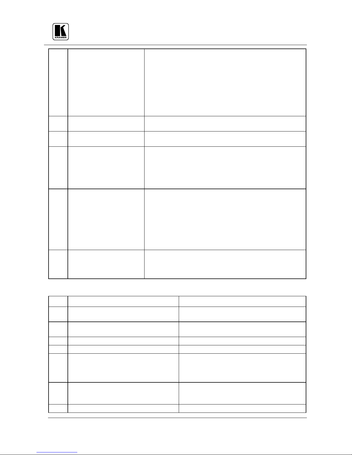
Table 1: VS-1604 Front Panel Features
No. Feature Function
1.
INPUT SELECTOR
buttons
2.
OUTPUT SELECTOR
buttons
3.
VIDEO OUTPUT STATUS
4.
AUDIO OUTPUT STATUS
5.
POWER Switch
6.
ALL
7.
OFF
8.
TAKE
Select the desired input to be switched to the output.
Select the desired output that the input signal is switched to.
Displays the selected video input switched to the output above
Displays the selected audio input switched to the output above
Illuminated switch: supplies power to the unit.
When pressed followed by an input button, connects that
audio/video input to all audio/video outputs.
When pressed after pushing an output button, disconnects that
video/audio output from the video/audio input. To disconnect all
the outputs, press the ALL button followed by the OFF button.
The machines can operate either in "Take" mode or in
KRAMER ELECTRONICS, LTD.
4
"
Normal"
(no user confirmation for each action is needed)
mode. Pressing the TAKE button toggles the mode and the
button illuminates when in "Take Mode". In "Take Mode", any
action would cause the TAKE button to blink before
implementation, and the user is required to press TAKE again in
order to confirm the operation.
NOTE
To cancel any operation initiated by pressing a button, press
the same button again.
9.
VIDEO
10.
AUDIO
11.
AFV illuminated button
12.
STO illuminated button
13.
RCL illuminated button
When pressed, illuminates and selects the video mode
(Breakaway) to enable modification of the video crosspoints.
When pressed, illuminates and selects the audio mode
(Breakaway) to enable modification of the audio crosspoints.
When pressed, illuminates and selects the "Audio Follow
Video" function. If the audio configuration differs from the
video configuration, the INPUT STATUS display flashes the
audio outputs that are to be reconfigured for AFV operation. In
such case, the TAKE button must be pressed to confirm the
modification.
Should be pressed, followed by an input or output pushbutton to
store the current status in the non-volatile memory. For example:
Press STO followed by INPUT 4 button to store Setup#4 in the
non-volatile memory.
NOTE
To delete a setup from the memory, press the STO and RCL
buttons simultaneously, followed by the input button (Setup
number) to be deleted.
Should be pressed, followed by an input or output pushbutton to
select a predetermined setup For example, press RCL followed
by INPUT 4 button to recall Setup#4 from the non-volatile
memory.
Table 2: VS-1604 Rear Panel Features
No. Feature Function
14.
15.
16.
17.
18.
19.
20.
1-16 AUDIO INPUTS terminal blocks
1-4 AUDIO OUTPUTS terminal blocks
VIDEO INPUTS BNC connectors Video inputs used to connect the video sources.
VIDEO OUTPUTS
Setup DIP switches
RS-485 terminal block
DB-9 female RS-232 connector
KRAMER ELECTRONICS, LTD.
Audio inputs used to connect the stereo audio
input sources.
Audio outputs used to connect the stereo audio
output acceptors.
BNC connectors Video outputs used to connect the video acceptors.
Allow proper configuration of the control signals
received and transmitted through the RS-232 (or
RS-485) control port, master/slave modifications,
line termination and device ID numbers.
Used for bi-directional communication with
another matrix switcher or PC through RS-485
interface.
Used for control of the matrix switcher from a PC,
5
 Loading...