

Page 1

Kramer Electronics, Ltd.
USER MANUAL
Model:
VP-81SID
Page 2

Contents
i
1 Introduction 1
2 Getting Started 1
2.1 Quick Start 1
3 Overview 3
3.1 Defining EDID 4
3.2 About HDMI—General Description 4
3.3 About HDCP—General Description 5
3.4 About the Power Connect™ Feature 5
3.5 Using Twisted Pair Cable 5
4 Defining the VP-81SID 8x1 Digital STEP-IN Switcher 6
4.1 Using the IR Transmitter for the VP-81SID 9
5 Installing in a Rack 10
6 Connecting the VP-81SID 8x1 Digital STEP-IN Switcher 11
6.1 Connecting to a Balanced Audio Acceptor 12
6.2 Connecting Remote Contact Input and Output Selection Switches 12
6.3 Connecting to the VP-81SID via the RS-232 Port 14
6.4 Connecting to the VP-81SID via the RS-485 Port 14
6.5 Connecting to the VP-81SID via the Ethernet Port 16
7 Operating the VP-81SID Locally via the Front Panel Buttons 18
7.1 Selecting an Input 18
7.2 Muting the Input when using Step-In Commanders 18
7.3 Resetting all Input Priorities to the Default 18
7.4 Selecting an Output 19
7.5 Setting the Audio Output Volume 19
7.6 Locking and Unlock the Front Panel Buttons 19
7.7 Muting the Audio 19
7.8 Muting the Audio on an Active Input. 19
8 Operating the VP-81SID Remotely 20
8.1 VP-81SID Step-In Controller Software 20
9 Operating the VP-81SID Remotely via the Embedded Web Pages 29
9.1 To Log On to the VP-81SID Web Pages 29
9.2 The VP-81SID Panel Page 31
9.3 The VP-81SID Audio Volume Page 33
9.4 The VP-81SID Priority Page 33
9.5 The VP-81SID Settings Page 34
10 Wiring the TP RJ-45 Connectors 35
11 Technical Specifications 36
12 Default Communication Parameters 37
13 Default EDID 37
Page 3

KRAMER: SIMPLE CREATIVE TECHNOLOGY
Contents
ii
14 Protocol 3000 Syntax 41
14.1 Host Message Format 41
14.2 Simple Command 41
14.3 Command String 41
14.4 Device Message Format 41
14.5 Device Long Response 41
14.6 Command Terms 42
14.7 Entering Commands 42
14.8 Bi-directional definition 43
14.9 Command Forms 43
14.10 Command Chaining 43
14.11 Maximum String Length 43
14.12 Backward Support 43
Figures
Figure 1: VP-81SID 8x1 Digital STEP-IN Switcher Front Panel 6
Figure 2: VP-81SID 8x1 Digital STEP-IN Switcher Rear Panel 7
Figure 3: Connecting the VP-81SID 8x1 Digital STEP-IN Switcher 11
Figure 4: Balanced Stereo Audio Output Connection 12
Figure 5: Remote Input Selection Switch Wiring 13
Figure 6: RS-485 Termination DIP-switch 15
Figure 7: Control of Multiple VP-81SID Devices via RS-232 and RS-485 16
Figure 8: Local Area Connection Properties Window 17
Figure 9: Internet Protocol (TCP/IP) Properties Window 17
Figure 10: Step-In Software Main Window 21
Figure 11: Typical Input Button 22
Figure 12: Log In Window 23
Figure 13: Connection Method Window 24
Figure 14: Input Selection 24
Figure 15: SID-X1 Input Selection 25
Figure 16: Changing the Output Volume 26
Figure 17: Input Button Properties Window 27
Figure 18: Java Test Page Success Message 29
Figure 19: The Loading Page 30
Figure 20: First Time Security Warning 30
Figure 21: VP-81SID Panel Page 31
Figure 22: Logging In 32
Figure 23: Selecting an Input 32
Figure 24: Selecting an Output 32
Figure 25: Locking the Front Panel Buttons 33
Figure 26: VP-81SID Audio Volume Page 33
Figure 27: VP-81SID Priority Page 33
Figure 28: VP-81SID Settings Page 34
Figure 29: TP Pinout Wiring 35
Page 4

Contents
iii
Tables
Table 1: VP-81SID 8x1 Digital STEP-IN Switcher Front Panel Features 6
Table 2: VP-81SID 8x1 Digital STEP-IN Switcher Rear Panel Features 7
Table 3: Remote Contact Terminal Block Connections 13
Table 4: Main Window Features 21
Table 5: Button Characteristics 22
Table 6: Menu Bar Options 23
Table 7: VP-81SID Panel Page Features 31
Table 8: VP-81SID Settings Page Features 34
Table 9: TP PINOUT 35
Table 10: Technical Specifications of the VP-81SID 36
Table 11: Communication Parameters 37
Table 12: Communication Commands 43
Page 5

Introduction
1
1 Introduction
Welcome to Kramer Electronics! Since 1981, Kramer Electronics has been
providing a world of unique, creative, and affordable solutions to the vast range of
problems that confront the video, audio, presentation, and broadcasting
professional on a daily basis. In recent years, we have redesigned and upgraded
most of our line, making the best even better! Our 1,000-plus different models now
appear in 11 groups
1
that are clearly defined by function.
Congratulations on purchasing your Kramer VP-81SID 8x1 Digital STEP-IN
Switcher.
The VP-81SID is ideal for:
• Display systems requiring simple input selection
• Remote monitoring of computer activity in schools and businesses
• Rental/staging applications
• Multimedia and presentation source selection
The package includes the following items:
• VP-81SID 8x1 Digital STEP-IN Switcher
• Power cord
• Infrared RC-IR3 remote control transmitter (including the required battery
and a separate user manual
2
)
• This user manual
2
2 Getting Started
We recommend that you:
• Unpack the equipment carefully and save the original box and packaging
materials for possible future shipment
• Review the contents of this user manual
• Use Kramer high performance high resolution cables
3
2.1 Quick Start
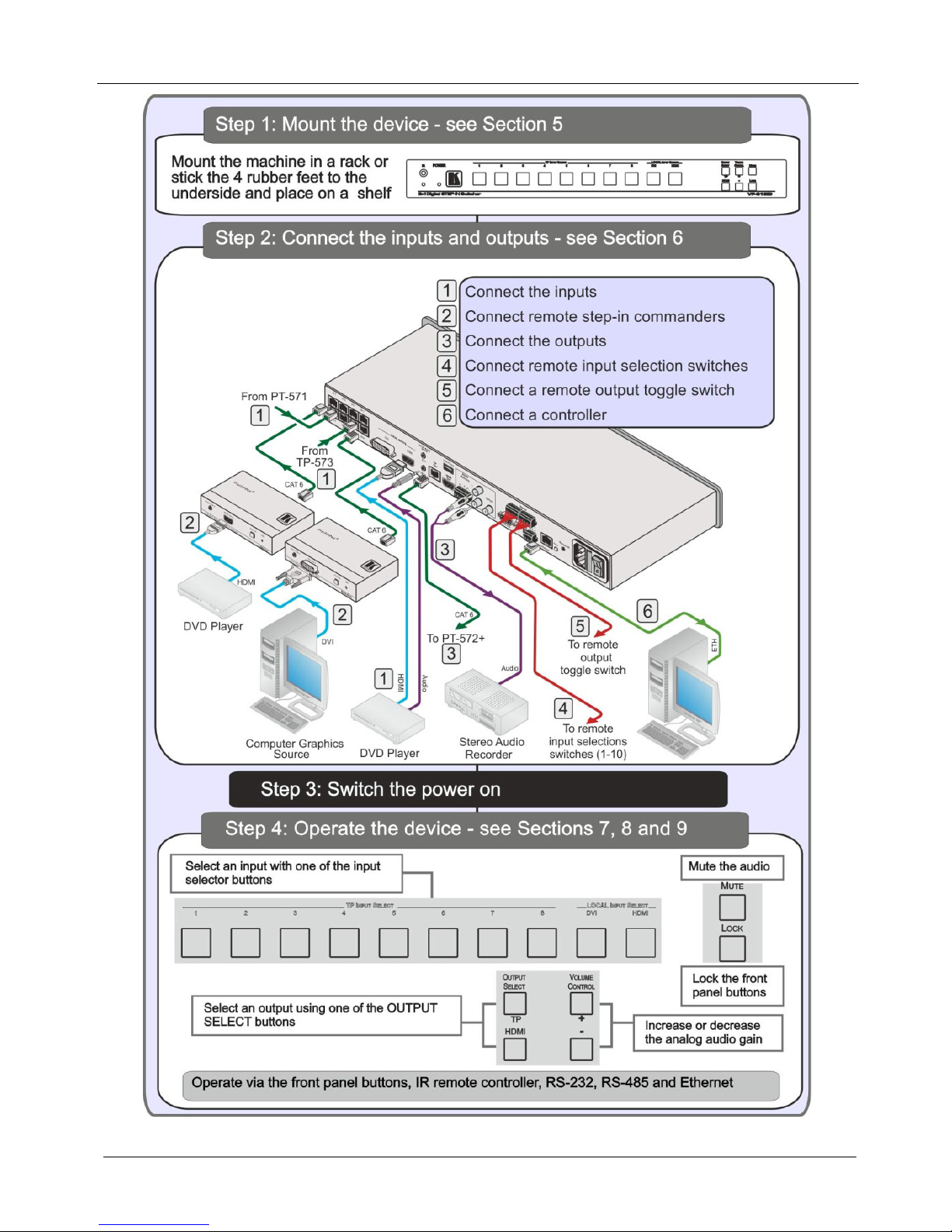
This quick start chart summarizes the basic setup and operation steps.
1 GROUP 1: Distribution Amplifiers; GROUP 2: Switchers and Routers; GROUP 3: Control Systems; GROUP 4: Format/Standards
Converters; GROUP 5: Range Extenders and Repeaters; GROUP 6: Specialty AV Products; GROUP 7: Scan Converters and Scalers;
GROUP 8: Cables and Connectors; GROUP 9: Room Connectivity; GROUP 10: Accessories and Rack Adapters; GROUP 11: Sierra
Products
2 Download up-to-date Kramer user manuals from http://www.kramerelectronics.com
3 The complete list of Kramer cables is available from http://www.kramerelectronics.com
Page 6
KRAMER: SIMPLE CREATIVE TECHNOLOGY
Getting Started
2
Page 7

Overview
3
3 Overview
The VP-81SID can route one of eight TP (Twisted Pair), a DVI or an HDMI input
to either a TP or an HDMI output. Input selection can also be controlled remotely;
• Using Step-In modules (for example, the SID-DP)
• Contact closure switches
• A serial controller via RS-232 or RS-485
• A PC via Ethernet connected over a LAN
The device also outputs balanced and unbalanced stereo audio, as well as digital
audio.
In particular, the VP-81SID:
• Has a bandwidth of 1.65Gbps per video channel
• Can be cascaded with up to four VP-81SID devices via the HDMI port to
provide up to 37 Twisted Pair inputs
• Supports the SID range of Step-in Commander panels for remote inputs and
remote step-in control
• Has a USB power port that can provide power to USB devices, (for
example, the Kramer KW-11T)
• Is HDCP compliant
• Provides EDID capture – Copies and stores the EDID from a display device
You can control the VP-81SID using the front panel buttons, or remotely via:
• RS-485 or RS-232 serial commands transmitted by a touch screen system,
PC or other serial controller
• Ethernet over a LAN
• The Kramer RC-IR3 Infrared Remote Control Transmitter or the
C-A35M/IRR-50 infrared remote extension cable transmitter (optional)
To achieve the best performance:
• Connect only good quality connection cables, thus avoiding interference,
deterioration in signal quality due to poor matching, and elevated noise
levels (often associated with low quality cables)
• Avoid interference from neighboring electrical appliances that may
adversely influence signal quality and position your VP-81SID away from
moisture, excessive sunlight and dust
Page 8

KRAMER: SIMPLE CREATIVE TECHNOLOGY
Overview
4
3.1 Defining EDID
The Extended Display Identification Data (EDID
1
) is a data-structure, provided by
a display that describes its capabilities to a graphics card (that is connected to the
display’s source). The EDID enables the PC or laptop to “know” what kind of
monitor is connected to the output. The EDID includes the manufacturer’s name,
product type, timing data supported by the display, display size, luminance data
and (for digital displays only) pixel mapping data.
3.2 About HDMI—General Description
High-Definition Multimedia Interface (HDMI) is an uncompressed all-digital
2
audio/video interface, widely supported in the entertainment and home cinema
industry. It delivers the highest high-definition image and sound quality. Note that
Kramer Electronics Limited is an HDMI Adopter and an HDCP Licensee.
In particular, HDMI
3
:
• Provides a simple
4
interface between any audio/video source, such as a settop box, DVD player, or A/V receiver and video monitor, such as a digital
flat LCD / plasma television (DTV), over a single lengthy
5
cable
• Supports standard, enhanced, high-definition video, and multi-channel
digital audio
6
on a single cable
• Transmits all ATSC HDTV standards and supports 8-channel digital audio,
with bandwidth to spare to accommodate future enhancements and
requirements
• Benefits consumers by providing superior, uncompressed digital video
quality via a single cable
7
, and user-friendly connector
• Is backward-compatible with DVI (Digital Visual Interface)
• Supports two-way CEC communication between the video source (such as a
DVD player) and the digital television, enabling new functionality such as
automatic configuration and one-button play
1 Defined by a standard published by the Video Electronics Standards Association (VESA)
2 Ensuring an all-digital rendering of video without the losses associated with analog interfaces and their unnecessary digital-to-analog
conversions
3 HDMI, the HDMI logo and High-Definition Multimedia Interface are trademarks or registered trademarks of HDMI licensing LLC
4 With video and multi-channel audio combined into a single cable, the cost, complexity, and confusion of multiple cables currently
used in A/V systems is reduced
5 HDMI technology has been designed to use standard copper cable construction at up to 15m
6 HDMI supports multiple audio formats, from standard stereo to multi-channel surround-sound. HDMI has the capacity to support
Dolby 5.1 audio and high-resolution audio formats
7 HDMI provides the quality and functionality of a digital interface while also supporting uncompressed video formats in a simple, cost-
effective manner
Page 9

Overview
5
• HDMI has the capacity to support existing high-definition video formats
(720p, 1080i, and 1080p, 2K and 4K), standard definition formats such as
NTSC or PAL, as well as 480p and 576p.
3.3 About HDCP—General Description
The High-Bandwidth Digital Content Protection (HDCP) standard developed by
Intel, protects digital video and audio signals transmitted over DVI or HDMI
connections between two HDCP-enabled devices to eliminate the reproduction of
copyrighted material. To protect copyright holders (such as movie studios) from
having their programs copied and shared, the HDCP standard provides for the
secure and encrypted transmission of digital signals.
3.4 About the Power Connect™ Feature
The Power Connect™ feature here means that digital Step-In Commanders (for
example, the SID-DP and SID-DVI) do not require an independent power supply
if the distance between the VP-81SID and the Step-In Commander does not exceed
50m (164ft). The Power Connect™ feature applies as long as the cable can carry
power. For longer distances heavy gauge cable or a power adapter should be used.
Note: Analog Step-In Commanders (for example, the SID-VGA and SID-X1) do
require independent power supplies.
3.5 Using Twisted Pair Cable
Kramer engineers have developed special twisted pair cables to best match our
digital twisted pair products; the Kramer BC-DGKat623 (CAT 6 23 AWG cable),
and the Kramer BC-DGKat7a23 (CAT 7a 23 AWG cable). These specially built
cables significantly outperform regular CAT 6/CAT 7a cables.
In applications where plenum cable is required, use the Kramer BCP-DGKat724
(CAT 7 23 AWG cable).
Page 10

KRAMER: SIMPLE CREATIVE TECHNOLOGY
Defining the VP-81SID 8x1 Digital STEP-IN Switcher
6
4 Defining the VP-81SID 8x1 Digital STEP-IN Switcher
Figure 1 and Table 1 define the front panel of the VP-81SID 8x1 Digital STEP-IN Switcher.
Figure 1: VP-81SID 8x1 Digital STEP-IN Switcher Front Panel
Table 1: VP-81SID 8x1 Digital STEP-IN Switcher Front Panel Features
# Feature Function
1
IR
LED Lights yellow when receiving an IR signal
2 Sensor Receives the signal transmitted by an IR remote control
3 POWER LED Lights green when the device is powered on
4 TP INPUT SELECT Buttons (1 to 8) Press to select one of the TP inputs
5
LOCAL INPUT SELECT Buttons
DVI Press to select the DVI input
6 HDMI Press to select the HDMI input
7
OUTPUT SELECT Buttons
HDMI Press to select the HDMI output
8 TP Press to select the TP output
9
VOLUME CONTROL Buttons
+
Press to increase the analog audio output volume
10
–
Press to decrease the analog audio output volume
11 MUTE Button Press to mute the external audio output
12 LOCK Button Press and hold to lock the front panel buttons. Press and hold again to unlock
the buttons
Page 11

Defining the VP-81SID 8x1 Digital STEP-IN Switcher
7
Figure 2 and Table 2 define the rear panel of the VP-81SID 8x1 Digital STEP-IN Switcher.
Figure 2: VP-81SID 8x1 Digital STEP-IN Switcher Rear Panel
Table 2: VP-81SID 8x1 Digital STEP-IN Switcher Rear Panel Features
# Feature Function
1 TP Input RJ-45 Connectors IN 1 to IN 8 Connect to the remote TP sources (1 to 8) using CAT 6 or higher specification cable.
These ma y be step-in panels (for exam ple, SID-DP) or TP transmitters (for example, the
PT-571 or TP-573)
2
LOCAL INPUTS
DVI Connect to the local DVI source
3 HDMI Connect to the local HDMI source
4 TP OUT RJ-45 Connector Connect to the remote TP receiver, for example, PT-572+, using CAT 6 or higher
specification cable (maximum 50m, 164ft)
5 USB POWER Connector Connect any device requiring USB power, (for example, the Kramer KW-11T)
6 RS-232 9-pin D-sub Port (F) Connect to a serial controller (see Section 6.3)
7 RE MOTE 12-way Terminal Block Connect to remote contact closure input and output selection switches (see Section 6.2)
8 ETHERNET RJ-45 Connector Connect to a PC or LAN for remote control via Ethernet (see Section 6.5)
9 AC Mains Power Socket Connect to the AC mains power
10 AC Mains Fuse AC mains supply protection fuse
11 AC Mains Power Switch Turns the AC mains power supply to the device on and off
Page 12

KRAMER: SIMPLE CREATIVE TECHNOLOGY
Defining the VP-81SID 8x1 Digital STEP-IN Switcher
8
# Feature Function
12
LOCAL AUDIO INPUTS
DVI Connect to the local DVI audio source
13 HDMI Connect to the local HDMI audio source
14 HDMI OUT Connector Connect to the local HDMI acceptor
15
AUDIO OUTPUTS
+L–G+R– Connect to the balanced audio acceptor (see Section 6.1)
16 L Connect to the unbalanced audio acceptor left channel
17 R Connect to the unbalanced audio acceptor right channel
18 S/PDIF Connect to the digital audio acceptor
19 PROG TERM DIP-Switch DIP-Switch 1: Sets the RS-485 bus termination (see Section 6.4.2)
Up = Off, Down = On. Default = On
DIP-Switch 2: For the use of Kramer service personnel only
20 RS-485 3-way Terminal Block Connect to RS-485 port on a remote controller or another VP-81SID.
Connect: G to Ground, A to A, and B to B (see Section
6.4)
21 RESET Button Press while power-cycling the device to reset parameters to factory default values
22 REMOTE IR 3.5mm Mini Jack
Connect to an external IR receiver unit for controlling the device via an IR remote controller
(see Section 4.1)
Page 13

Defining the VP-81SID 8x1 Digital STEP-IN Switcher
9
4.1 Using the IR Transmitter for the VP-81SID
You can use the RC-IR3 IR transmitter to operate the VP-81SID via the built-in
IR receiver on the front panel or, instead, via an optional external IR receiver
1
. The
external IR receiver can be located 15m (49ft) away from the device. This distance
can be extended to up to 60m (197ft) when used with three extension cables
2
.
Before using the external IR receiver, be sure to arrange for your Kramer dealer to
insert the internal IR connection cable
3
with the 3.5mm mini jack that fits into the
REMOTE IR opening on the rear panel. Connect the external IR receiver to the
REMOTE IR 3.5mm mini jack.
1 Model: C-A35M/IRR-50
2 Model: C-A35M/A35F-50
3 P/N: 505-70434010-S
Page 14
KRAMER: SIMPLE CREATIVE TECHNOLOGY
Installing in a Rack
10
5 Installing in a Rack
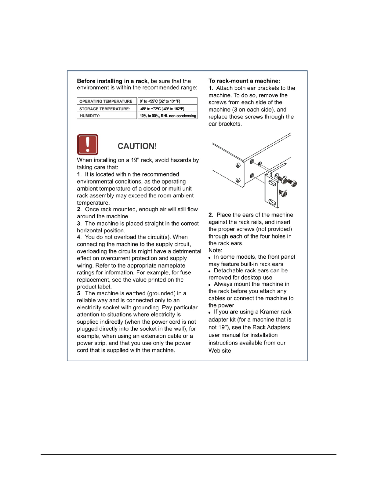
This section describes the preparation and installation of the unit in a rack.
Page 15

Connecting the VP-81SID 8x1 Digital STEP-IN Switcher
11
6 Connecting the VP-81SID 8x1 Digital STEP-IN Switcher
Figure 3: Connecting the VP-81SID 8x1 Digital STEP-IN Switcher
To connect1 the VP-81SID, as illustrated in the example in Figure 3:
1. Connect up to eight
2
remote Step-in Commanders3 (for example, the SID-H
and SID-DVI Step-In Commander panels up to 50m (164ft) away) or TP
transmitters (for example, the PT-571 and TP-573) to the VP-81SID RJ-45
TP INPUT connectors.
2. Connect a DVI video source (for example, a computer graphics source) to the
LOCAL INPUTS DVI connector, and the computer’s unbalanced stereo audio
source to the LOCAL AUDIO INPUT DVI connector.
3. Connect an HDMI video source to the LOCAL INPUTS HDMI connector.
1 Be sure that the power is switched off to each device before connecting it to your VP-81SID. After connecting all the devices to your
VP-81SID, switch on the power to the VP-81SID, and then switch on the power to each device
2 You do not have to connect all the inputs
3 Any combination of Step-In panels and TP transmitters up to a maximum of eight
Page 16
KRAMER: SIMPLE CREATIVE TECHNOLOGY
Connecting the VP-81SID 8x1 Digital STEP-IN Switcher
12
4. Connect the TP OUT RJ-45 connector to a compatible TP receiver up to 50m
(164ft), for example, PT-572+.
5. Connect the S/PDIF RCA digital audio output to an audio acceptor (for
example, a DAT recorder).
6. Connect the balanced audio 5-pin terminal block (see Section
6.1) to an audio
acceptor (for example, a balanced stereo audio amplifier).
7. Optional—Connect up to ten remote, contact closure input selection switches
to the REMOTE terminal block (see Section
6.2).
8. Optional—Connect the Ethernet RJ-45 TP port directly or via a LAN to a PC
controller.
Alternatively, you can connect a PC and/or controller to the:
RS-232 port (see Section
6.3)
RS-485 port (see Section
6.4)
9. Connect the power cord
1
.
Note: When signal sources are disconnected from inputs, signal acceptors (for
example, a projector) may not go into standby mode automatically. We therefore
recommend that you turn off the VP-81SID and/or the acceptor.
Note: When using the PT-572+ in conjunction with the VP-81SID do not connect
the 12V power supply to the PT-572+.
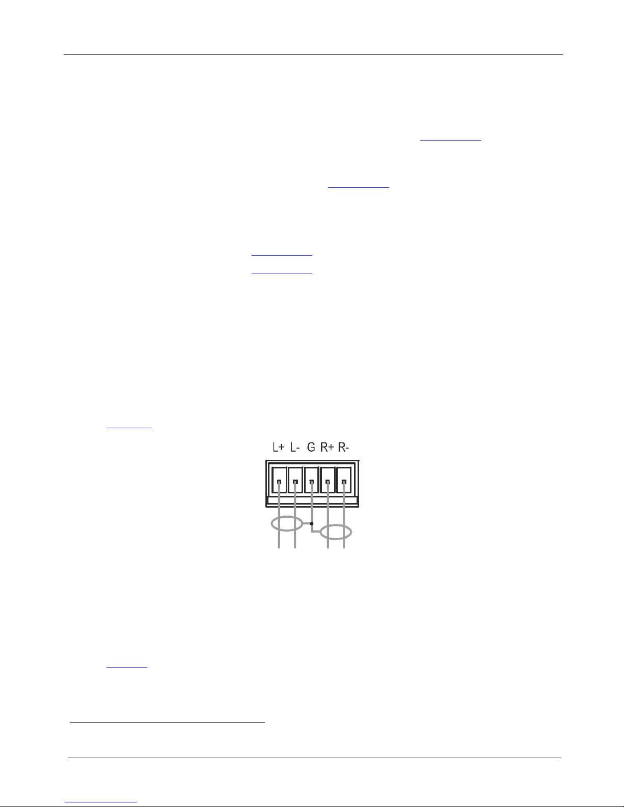
6.1 Connecting to a Balanced Audio Acceptor
Figure 4 illustrates how to wire devices to the balanced audio output.
Figure 4: Balanced Stereo Audio Output Connection
6.2 Connecting Remote Contact Input and Output Selection Switches
You can connect remote, contact closure input selection switches to the REMOTE
terminal block on the rear panel of the VP-81SID. Remote input selection switches
provide the ability to remotely activate the inputs and an output.
Table 3 lists the remote contact terminal block connections.
1 We recommend that you use only the power cord that is supplied with the device
Page 17

Connecting the VP-81SID 8x1 Digital STEP-IN Switcher
13
Table 3: Remote Contact Terminal Block Connections
Terminal
Number
Description
1 Connect to ground to select input 1
2 Connect to ground to select input 2
3 Connect to ground to select input 3
4 Connect to ground to select input 4
5 Connect to ground to select input 5
6 Connect to ground to select input 6
7 Connect to ground to select input 7
8 Connect to ground to select input 8
9 Connect to ground to select input 9
10 Connect to ground to select input 10
11 Connect to ground to toggle between output 1 and output 2
G Ground
The following example (see Figure 5) illustrates three switches (1, 8 and A)
connected so as to remotely control inputs 1 and 8, and select an output
respectively. Connected as shown, pressing switch 1 causes input 1 on the
VP-81SID to be the active input, and pressing switch 8 causes input 8 to be the
active input. Pressing switch A causes the output selection to toggle between the
TP and HDMI outputs.
Figure 5: Remote Input Selection Switch Wiring
To connect remote input/output selection switches as illustrated in the
example in
Figure 5:
1. Connect Switch 1 to pins 1 and G on the terminal block (remote step-in for
input 1).
2. Connect Switch 8 to pins 8 and G on the terminal block (remote step-in for
input 8).
3. Connect Switch A to pins 11 and G on the terminal block (remote output
selection toggle).
Page 18

KRAMER: SIMPLE CREATIVE TECHNOLOGY
Connecting the VP-81SID 8x1 Digital STEP-IN Switcher
14
6.3 Connecting to the VP-81SID via the RS-232 Port
You can connect to the VP-81SID via an RS-232 connection using, for example, a
PC (see Section
12). Note that a null-modem adapter/connection is not required.
To connect to the VP-81SID via RS-232:
• Connect the RS-232 9-pin D-sub rear panel port on the VP-81SID unit via a
9-wire straight cable (only pin 2 to pin 2, pin 3 to pin 3, and pin 5 to pin 5
need to be connected) to the RS-232 9-pin D-sub port on your PC
6.4 Connecting to the VP-81SID via the RS-485 Port
You can operate the VP-81SID via the RS-485 port from a distance of up to
1200m (3900ft) using any device equipped with an RS-485 port (for example, a
PC). For successful communication, you must set the RS-485 machine number and
bus termination.
To connect a device with a RS-485 port to the VP-81SID:
1. Connect the TxD+ pin on the RS-485 port of the PC to the A pin on the
RS-485 port on the rear panel of the VP-81SID.
2. Connect the TxD– pin on the RS-485 port of the PC to the B pin on the
RS-485 port on the rear panel of the VP-81SID.
3. If shielded TP cable is used, the shield may be connected to the G (ground)
pin on the unit.
6.4.1 Setting the RS-485 Machine Number
The machine number on the RS-485 bus can be set to between 1 and 4 and can be
set using the front panel buttons.
To set the RS-485 machine number using the front panel buttons:
1. Press the Lock button until the button lights.
The front panel buttons are locked.
2. Press the Local Input Select HDMI and Mute buttons at the same time.
The TP Input Select buttons flash.
3. Press the TP Input Select button number (1 to 4) for the required machine
number.
The TP Input Select buttons stop flashing and the selected TP Input Select
button lights.
4. Press the Lock button until the button is no longer lit.
The selected machine number is set and front panel buttons are unlocked.
Page 19

Connecting the VP-81SID 8x1 Digital STEP-IN Switcher
15
6.4.2 Setting the RS-485 Bus Termination
Figure 6 illustrates the factory default DIP-switch positions.
Figure 6: RS-485 Termination DIP-switch
DIP-switch 1 sets the RS-485 bus termination of the VP-81SID. Only the first and
last physical units on the RS-485 bus must be terminated, all others must be
unterminated. Moving the DIP-switch up turns the termination off (default),
moving the switch down enables the termination.
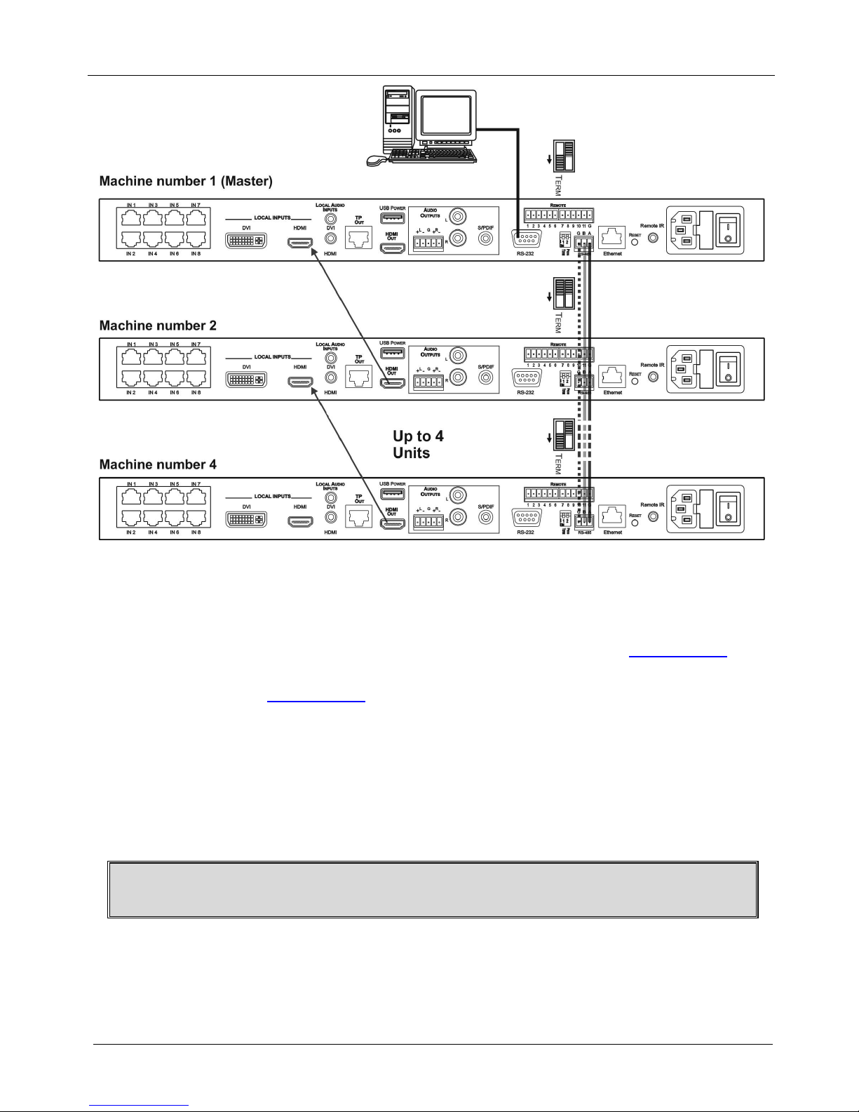
6.4.3 Connecting and Controlling Multiple VP-81SID Devices
You can connect up to four VP-81SID devices with operation via RS-232 (as
shown in the example in
Figure 7) or Ethernet. Connecting four devices provides
37 inputs.
To connect up to four VP-81SID devices:
1. Connect the RS-232 port
1
on the first VP-81SID device to the PC (see
Section
6.3).
2. Connect the RS-485 terminal block port on the first device to the RS-485 port
on the second device, and so on for all devices. (Connect A to A, B to B, and
G to G.)
3. Connect the HDMI LOCAL INPUT on the first device to the HDMI OUT on
the second device, and so on for all devices.
4. Set the machine number and termination as follows:
The first device is machine number 1 and the subsequent three devices
are machine numbers 2 to 4 (see Section
6.4.1)
Terminate the first and last devices, that is, terminate machine numbers 1
and 4 (see Section
6.4.2). Ensure that all other devices are left
unterminated
1 Alternatively, the RS-485 port could be used for PC control
Page 20
KRAMER: SIMPLE CREATIVE TECHNOLOGY
Connecting the VP-81SID 8x1 Digital STEP-IN Switcher
16
Figure 7: Control of Multiple VP-81SID Devices via RS-232 and RS-485
6.5 Connecting to the VP-81SID via the Ethernet Port
You can connect the VP-81SID via Ethernet in the following ways:
• For direct connection to the PC, use a crossover cable (see Section
6.5.1)
• For connection via a network hub or network router, use a straight through
cable (see Section
6.5.2)
Note: The following instructions are valid only if your PC uses a fixed IP address.
If your PC receives an IP address from a DHCP server, consult your IT department
regarding a suitable IP address.
6.5.1 Connecting Directly to the Ethernet Port
You can connect the Ethernet port of the VP-81SID to the Ethernet port on your
PC via a crossover cable with RJ-45 connectors.
This type of connection is recommended for identification of the factory
default IP address of the VP-81SID during the initial configuration
To connect the VP-81SID directly to a PC:
1. Using a crossover cable, connect the VP-81SID to the PC via the Ethernet
port on both units.
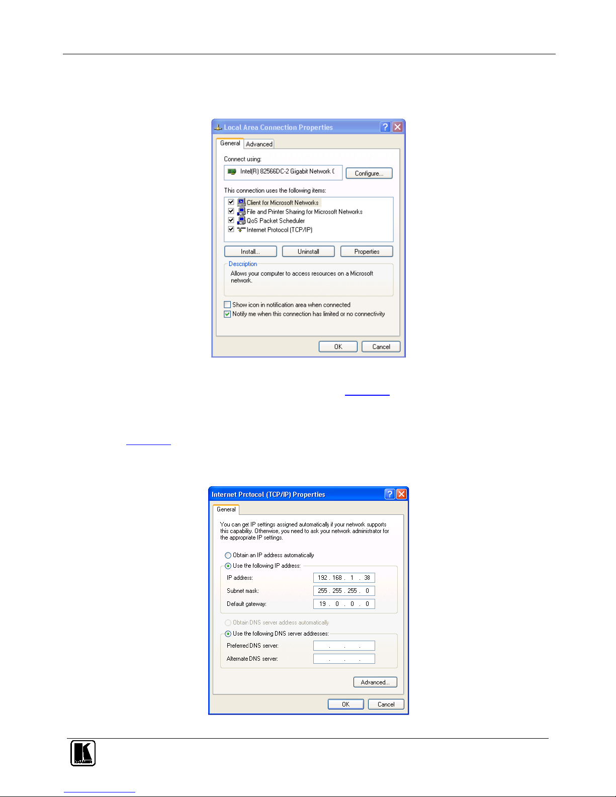
2. On the PC, click Start > Control Panel.
Page 21
Connecting the VP-81SID 8x1 Digital STEP-IN Switcher
17
3. Double-click Network Connections.
4. Right-click, and from the menu select Properties.
The Local Area Connection Properties window appears.
Figure 8: Local Area Connection Properties Window
5. Select Internet Protocol (TCP/IP) (see Figure 8).
6. Click the Properties button.
7. Select Use the following IP address, and fill in the details as shown in
Figure 9. You can use any IP address in the range 192.168.1.1 to
192.168.1.255 (excluding 192.168.1.39) that is provided by your IT
department.
Figure 9: Internet Protocol (TCP/IP) Properties Window
Page 22

KRAMER: SIMPLE CREATIVE TECHNOLOGY
Operating the VP-81SID Locally via the Front Panel Buttons
18
8. Click OK.
6.5.2 Connecting via a Network Hub, Switch, or Router
You can connect the Ethernet port of the VP-81SID to the Ethernet port on a
network hub, switch, or router, via a straight through cable with RJ-45 connectors.
The VP-81SID Ethernet port has to be configured to be compatible with your
network (see Section
8.1.13).
7 Operating the VP-81SID Locally via the Front Panel Buttons
Powering up the VP-81SID recalls the last settings (that is, the configuration of the
device when it was powered down) from the non-volatile memory.
7.1 Selecting an Input
The input buttons illuminate to indicate the following:
• Off indicates the input is not selected
• On indicates the input is selected
• Flashing indicates that you have tried to select the input but another input
with a higher priority is currently selected
To select an input:
• Press one of the ten front panel Input Select buttons. The selected button
lights
Note: Pressing an active input button mutes the input. Pressing the button again
unmutes the input.
Note: The priority of each input can be set individually using the Step-In
Commander panel.
7.2 Muting the Input when using Step-In Commanders
To mute and unmute the input when using a Step-In Commander:
1. Press the Input Select button on the Step-In Commander.
The input is selected and the buttons lights.
2. Press the Step In button on the Step-In Commander.
The input is muted and the button no longer lights.
3. Press the Step In button on the Step-In Commander a second time.
The input is unmuted and the button lights.
7.3 Resetting all Input Priorities to the Default
To reset all input priorities to the default priority (10):
1. Press the Lock button until the button lights.
The front panel buttons are locked.
Page 23

Operating the VP-81SID Locally via the Front Panel Buttons
19
2. Press the Volume Control + and – buttons at the same time.
All the TP Input Select buttons flash. When they stop flashing, the input
priorities have been reset to their defaults.
7.4 Selecting an Output
To select an output:
• Press one of the two front panel Output Select buttons.
The selected button lights.
7.5 Setting the Audio Output Volume
To set the audio output volume:
• Press either the Volume Control + (to increase the volume) or the Volume
Control – (to decrease the volume) button.
To mute the audio output:
• Press the Mute button.
The button lights and the audio is muted.
7.6 Locking and Unlock the Front Panel Buttons
To lock and unlock the front panel buttons:
1. Press the Lock button until it lights.
The front panel buttons are locked.
2. Press the Lock button until it no longer lights.
The front panel buttons are unlocked.
7.7 Muting the Audio
To mute and unmute the audio on an input:
1. Press the Mute button on the front panel of the VP-81SID.
The audio is muted and the button lights.
2. Press the Mute button on the front panel of the VP-81SID a second time.
The audio is unmuted and the button no longer lights.
7.8 Muting the Audio on an Active Input.
To mute and unmute the audio on an active input:
1. Press the Input button of the active input.
The button flashes and the input is muted.
2. Press the Input button a second time.
The input is unmuted and the button lights.
Page 24

KRAMER: SIMPLE CREATIVE TECHNOLOGY
Operating the VP-81SID Remotely
20
8 Operating the VP-81SID Remotely
The VP-81SID can be operated remotely via any of the following methods:
• The Step-in Controller software (see Section 8.1)
• Step-In Commander panels
• Contact closure switches (for connecting, see Section
6.2)
• RS-485 (for connecting, see Section
6.4) or RS-232 (for connecting, see
Section
6.3) serial commands transmitted by a touch screen system, PC or
other serial controller
• Ethernet over a LAN (for connecting, see Section
6.5)
• Remotely using the Kramer RC-IR3 Infrared Remote Control Transmitter
(refer to the RC-IR3 user manual) or the infrared remote extension cable
transmitter
• The embedded Web pages (see Section
9)
8.1 VP-81SID Step-In Controller Software
The Step-In Software requires the following:
• Windows™ XP, Vista or Windows™ 7
• Microsoft .Net Framework version 3
To install the Step-In Software, download the software and run the setup file. After
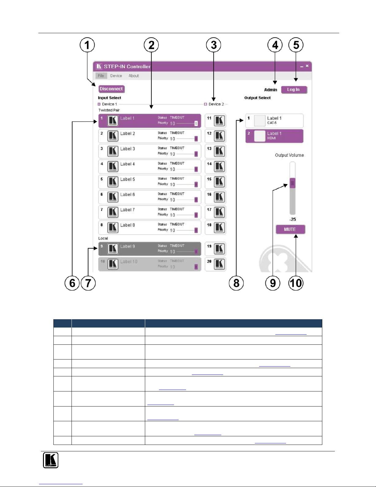
installation, running the Step-In Software for the first time displays a window
similar to that shown in
Figure 10.
The VP-81SID can operate in either the secure mode or the unsecure mode. The
factory default mode is unsecure. To change the mode, see Section
14.12.33. In the
secure mode, access can be via either Admin or User (see Section
8.1.1). When in
unsecure mode, full access is granted without Admin authorization.
Page 25
Operating the VP-81SID Remotely
21
Figure 10: Step-In Software Main Window
Table 4: Main Window Features
# Feature Function
1 Connect/Disconnect Button Click to connect to or disconnect from the device (see Section 8.1.4)
2 Selected Input Buttons Click to select an input. The selected input button is highlighted
3 Device 2 Cascaded
Device(s)
Inputs of any cascaded devices
4 Current User Label Indicates which user is currently logged in (see Section 8.1.3)
5 Log In Button Click to log in (see Section 8.1.3)
6 Inputs Twisted Pair Buttons Click one of the eight remote Twisted Pair input buttons to select an input
(see Section
6.3)
7 Local Input Buttons Click one of the two local input buttons to select an input (see
Section
6.3)
8 Outputs Buttons Click one of the two output buttons to select an output (see
Section
8.1.5)
9 Output Volume Slider Click, hold and move the slider up (higher) or down (lower) to adjust the
output volume (see Section
6.3)
10 Mute on/off Button Click to mute/unmute the output volume (see Section 8.1.7)
Page 26
KRAMER: SIMPLE CREATIVE TECHNOLOGY
Operating the VP-81SID Remotely
22
Note: When a change is made on the device (for example, a different output is
selected), the change is reflected almost immediately in the main window of the
Step-in Software, and visa versa.
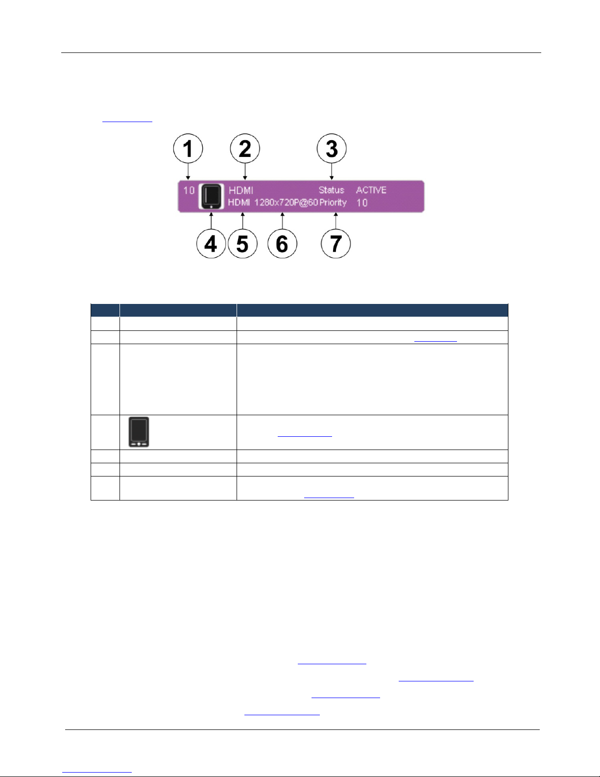
Figure 11
shows a typical input button.
Figure 11: Typical Input Button
Table 5: Button Characteristics
# Feature Description
1 10 Input (1–10) or output (1–2) channel number
2 HDMI Label User-selectable button label, Admin only (see Section 6.3)
3 Status ACTIVE Indicates the status of the connection and signal on the channel:
TIMEOUT—no cable
MUTE— cable present, no signal detected
WAIT— cable and signal present but channel is not selected
ACTIVE—cable and signal present and channel is selected (only one
channel at a time)
4
User-selectable icon selected to be displayed on the button, Admin
only (see Section
8.1.10)
5 HDMI Video input type: VGA, HDMI, DP, DVI
6 1280x720p@60 Video resolution, i=interlace/p=progressive, refresh rate
7 Priority 10 Slider Slider for adjusting the priority (1, lowest–10, highest) of the input,
Admin only (see Section
8.1.5)
8.1.1 Authorized Users
By default, you are logged in as User and you can:
• Select an active input or output
• Adjust or mute/unmute the output volume
• Change the device name
• Modify the IP configuration
Options that you are not authorized to perform are grayed out.
When logged in as Admin, in addition to the User abilities, you can:
• Modify the input priorities (see Section
8.1.9)
• Modify the input/output button characteristics (see Section
8.1.10)
• Upgrade the device firmware (see Section
8.1.5)
• Reset the device (see Section
8.1.12)
Page 27
Operating the VP-81SID Remotely
23
• Change the User and Admin Passwords
• Enable/disable IR control
Note: Any actions that you are not authorized to perform are grayed out.
8.1.2 The Step-in Software Menu Bar
The menu bar options are shown in Table 6.
Table 6: Menu Bar Options
Menu Bar
Options
Sub Menu Description
FILE Connect/Disconnect Connect or disconnect to the device
Exit Exit the Step-in software
DEVICE
Details
Retrieve and display the device details, such as, model, unit
name, version, and so on
Change Admin Password Change the Admin password
Cascade Select the number of cascaded devices
Firmware Update
Update the device firmware using a new firmware file (Admin
only)
Change Unit Password Change the Admin user password (Admin only)
Reset Power cycle the device (Admin only)
IR Status Enable or disable the IR control for the device
ABOUT NA Displays the Step-in Software and Kramer company details
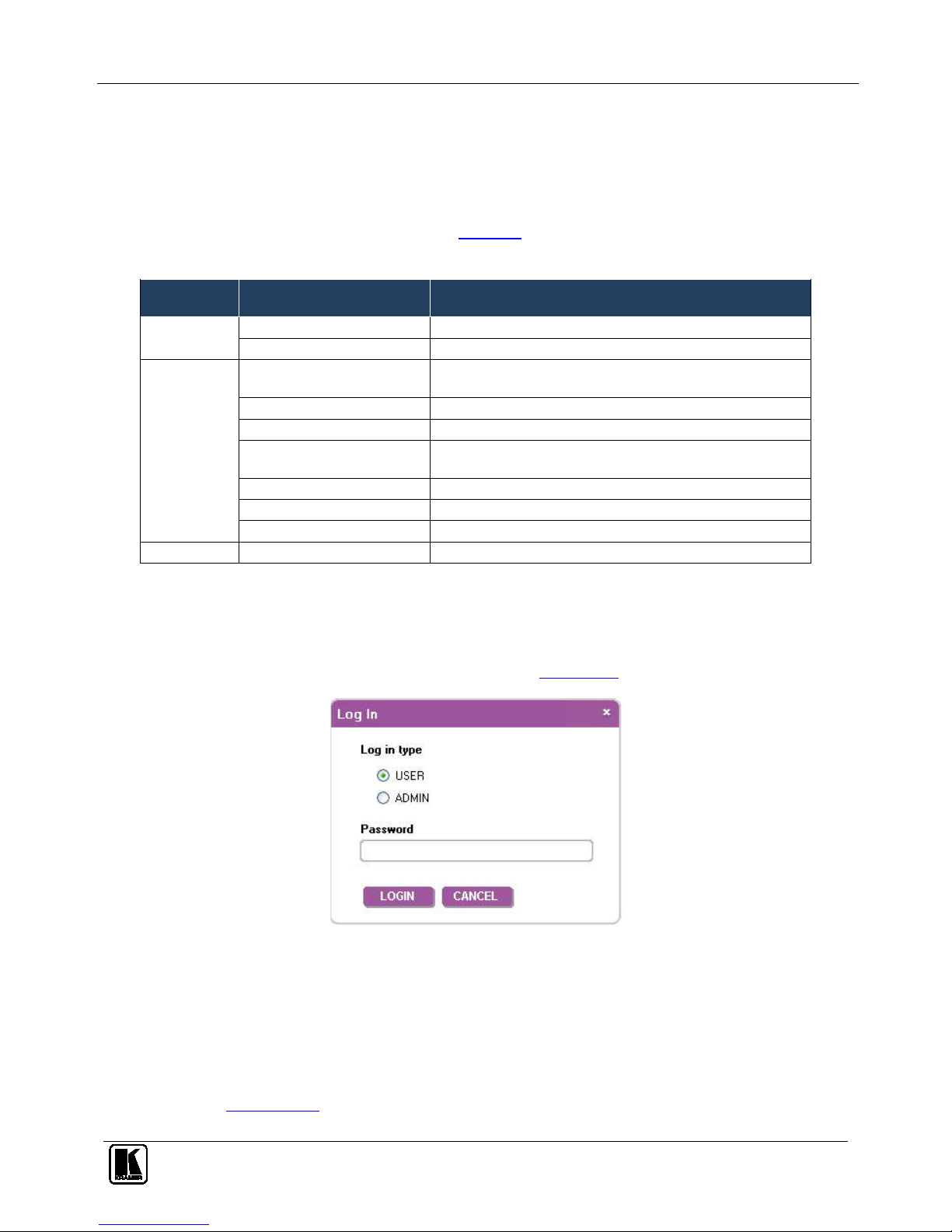
8.1.3 Logging in as Admin
To log in as admin:
1. Click the Log In button.
The Log In window appears as shown in
Figure 12.
Figure 12: Log In Window
2. Select either User or Admin using the radio buttons.
3. Enter the password.
The main window is displayed and the user shown is Admin.
4. To log out, click Log Out.
Note: By default there is no Admin password. To change the Admin password,
see Section
9.5.
Page 28
KRAMER: SIMPLE CREATIVE TECHNOLOGY
Operating the VP-81SID Remotely
24
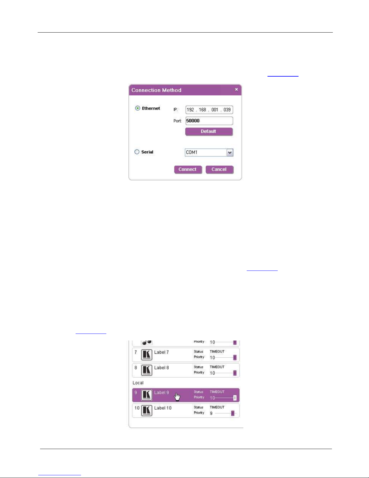
8.1.4 Connecting to the Device
To connect to the device:
1. Click the Connect button.
The Connection Method window is displayed as shown in
Figure 13.
Figure 13: Connection Method Window
2. Select the connection method (via Ethernet over a LAN or a serial connection)
by clicking the relevant radio button.
3. For Ethernet, enter the IP address and Port number of the device and click
Connect.
To set the default IP address and Port number, press the Default button.
4. For a serial connection, select the required Com port from the drop-down list.
5. Click Connect.
If the connection is successful, the window shown in
Figure 10 appears. If the
connection is not successful, a Timeout error message appears.
8.1.5 Switching an Input to an Output
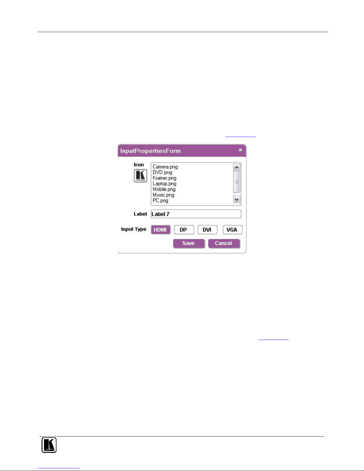
To switch an input to an output:
1. Click on the required twisted-pair or local input to switch.
The input is selected and the button changes to solid purple as shown in
Figure 17.
Figure 14: Input Selection
Page 29
Operating the VP-81SID Remotely
25
2. Click on the required output to select.
The switch selection is made and the button changes to solid purple.
Note: To switch an input to an output, you can click on either an input or an output
first, the order is not important.
8.1.6 Switching and Selecting an Input when using the SID-X1
To switch an input to an output:
1. Click on the TP input to which the SID-X1 is connected.
The switch selection is made and the button changes to solid purple.
2. Right-click on the input.
The InputPropertiesForm screen is shown as in
Figure 15.
Figure 15: SID-X1 Input Selection
3. Click on the required Input Type button.
The input type selection is made and the button changes to solid purple.
4. Click Save.
The Input type is selected on the SID-X1.
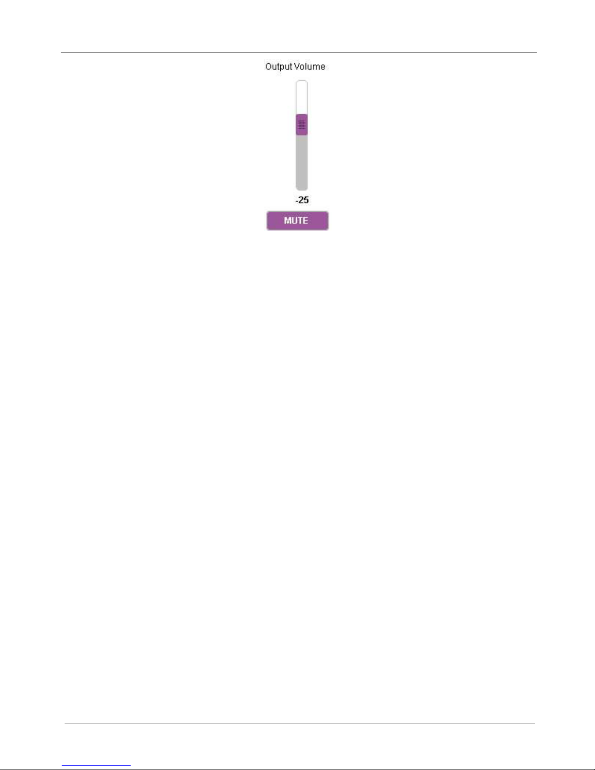
8.1.7 Changing the Output Volume
To change the output volume:
1. Click and hold on the Output Volume slider as shown in
Figure 17.
Page 30
KRAMER: SIMPLE CREATIVE TECHNOLOGY
Operating the VP-81SID Remotely
26
Figure 16: Changing the Output Volume
2. Drag up to increase or down to decrease the output volume.
The volume level changes accordingly.
8.1.8 Muting the Audio Output
To mute the audio output:
1. Click the Mute button.
The button changes to purple and the audio is muted.
2. Click the colored Mute button to unmute the audio.
The button changes to white and the audio is unmuted.
8.1.9 Changing the Priority of an Input
The priority of an input determines whether another input that is selected can take
control from it, where 1 is the lowest and 10 is the highest priority. For example,
input 4 has a priority of 2 and input 8 has a priority of 5. If input 8 is currently
selected, input 4 cannot take control. In this case, if you press input 4, the button
flashes for a few seconds and then goes off, indicating that input 4 is not selected.
To change the input priority you must be logged in as Admin.
To change the priority of an input:
• Click, hold and move the Priority slider on the relevant input to the
required priority, right to increase and left to decrease the priority.
8.1.10 Changing the Input and Output Button Icons and Labels
To change the input/output button icons and labels you must be logged in as
Admin.
Page 31
Operating the VP-81SID Remotely
27
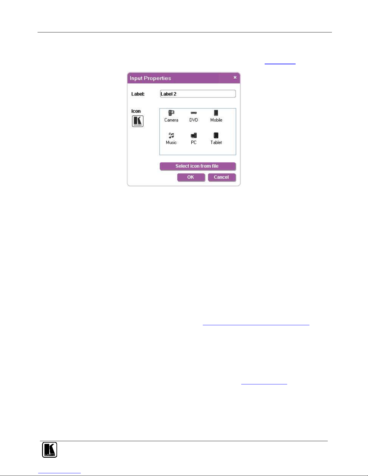
To change an input/output button icon and label:
1. Right-click on the relevant button.
The button Input Properties window appears as shown in
Figure 17.
Figure 17: Input Button Properties Window
2. In the Label text field, enter the required button label.
3. Either:
Select the required icon from the list (you can save custom icons in the
\Kramer Electronics\StepIn Controller\Images directory)
OR
Click Select icon from file and browse to the icon directory
4. Click OK.
The button characteristics are changed.
8.1.11 Updating the Firmware
To update the firmware you must be logged in as Admin.
To update the firmware:
1. Download the latest firmware file from
http:www.kramerelectronics.com.
2. Click Unit > Firmware Update.
3. Browse to the firmware file that you downloaded.
4. Click Open.
The device firmware is loaded.
Note: Do not interrupt the uploading process or the device may be damaged.
5. When the process is complete, reset the device (see Section
8.1.12).
8.1.12 Resetting the Device
To reset the device you must be logged in as Admin.
To reset the device:
1. Click Unit > Reset.
Page 32

KRAMER: SIMPLE CREATIVE TECHNOLOGY
Operating the VP-81SID Remotely
28
2. Click OK.
The device is reset.
8.1.13 Setting the IP Network Parameters
To set the IP network parameters you must be logged in as Admin.
To set the IP network parameters:
1. Click Unit > Device Details.
2. Under Connectivity, edit the required parameter.
3. Click Set Value.
A confirmation message appears.
4. Click OK.
The parameter is set.
5. Reset the device (see Section
8.1.13
).
8.1.14 Setting Multiple Cascaded Devices
You can control up to four devices via a single RS-232 or Ethernet connection
using the Step-In Software. Control of multiple devices is the same as for a single
device but you must first set the number of devices. The main window (see
Figure 10) then displays an extra column of input buttons for each device.
The number of devices can be set manually or automatically. We recommend that
you set the number of devices manually as the auto-scanning procedure can take
some time.
To set the number of devices:
1. From the menu bar, click Unit.
2. From the options, click Cascade.
3. Either:
Manually select the number of devices
OR
Select Auto.
The Step-In Software scans the RS-485 bus for active devices. This may
take a few minutes
8.1.15 Changing the Admin Password
By default, there is no Admin password. To change the Admin password, use the
embedded Web pages (see Section
9.5). You can only change the Admin password
if you are logged in as Admin.
Page 33
Operating the VP-81SID Remotely via the Embedded Web Pages
29
9 Operating the VP-81SID Remotely via the Embedded Web
Pages
The embedded Web pages can be used to remotely operate the VP-81SID using a
Web browser and an Ethernet connection.
Before attempting to connect:
• Perform the procedures in Section
6.5
.
• Ensure that the Java™ software is installed and functioning correctly on
your computer. If not, download it from
www.java.com
• Ensure that your browser is supported—Microsoft IE (V6.0 and higher),
Google Chrome, Firefox (V3.0 and higher).
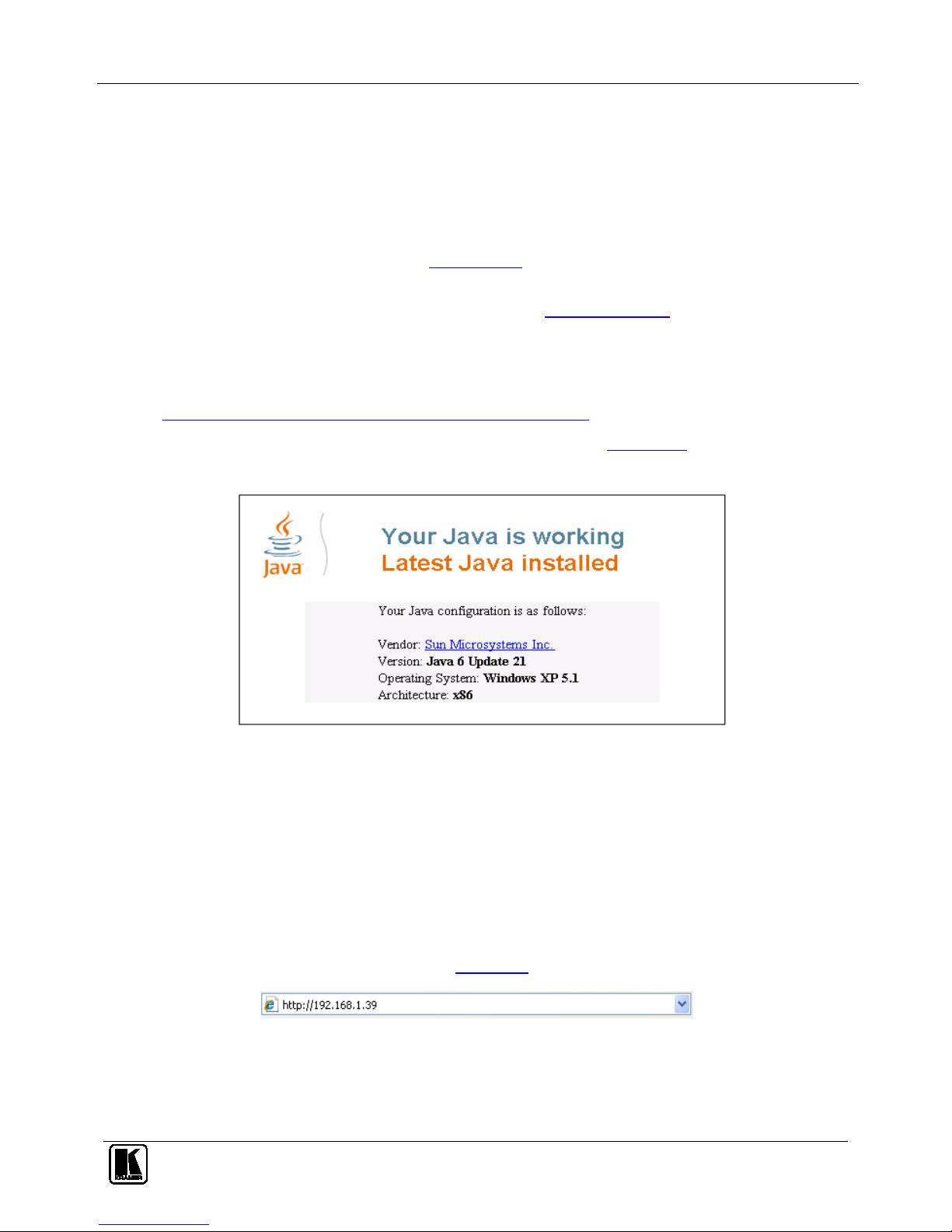
To check that Java is installed and running correctly, browse to
http://www.java.com/en/download/help/testvm.xml
This page runs a test and displays a Java success (see
Figure 18) or failure
message.
Figure 18: Java Test Page Success Message
If you do not see the success message, follow the instructions on the page to:
• Load and enable Java
• Enable Javascript in your browser
9.1 To Log On to the VP-81SID Web Pages
To log on to VP-81SID Web pages:
1. Open your Internet browser.
2. Type the unit’s IP number (see
Table 11) in the Address bar of your browser.
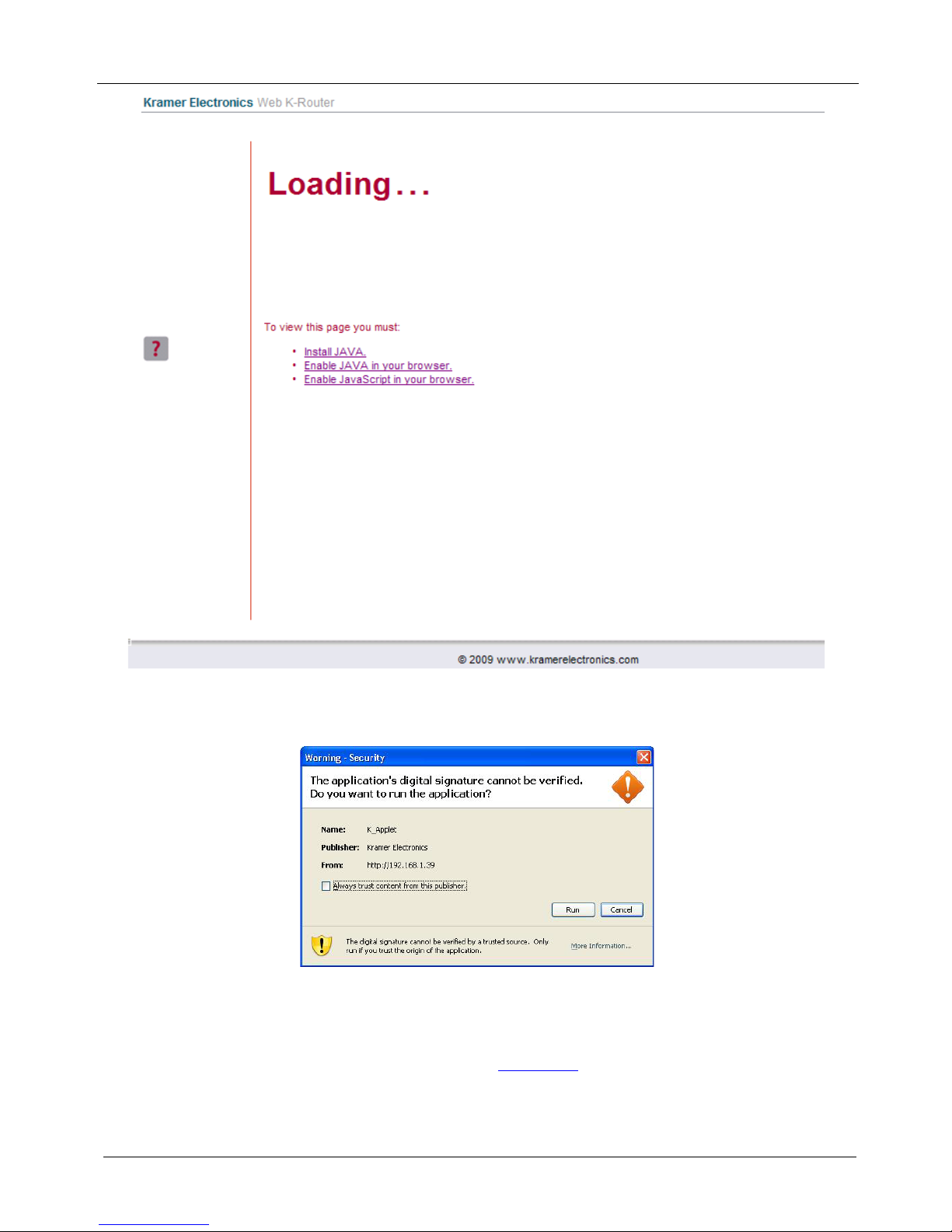
The Loading page appears.
Page 34
KRAMER: SIMPLE CREATIVE TECHNOLOGY
Operating the VP-81SID Remotely via the Embedded Web Pages
30
Figure 19: The Loading Page
The first time that you run the program, the Warning-Security screen appears.
Figure 20: First Time Security Warning
3. Click Run.
The main switching control Home page is displayed which shows a graphical
interpretation of the front panel (see
Figure 21).
The Web pages let you control the VP-81SID via Ethernet over a LAN. There are
four Web pages:
Page 35
Operating the VP-81SID Remotely via the Embedded Web Pages
31
• The Panel page (see Section 9.2)
• The Audio Volume page (see Section 9.3)
• The Priority page (See Section 9.4)
• The Settings page (see Section
9.5)
9.2 The VP-81SID Panel Page
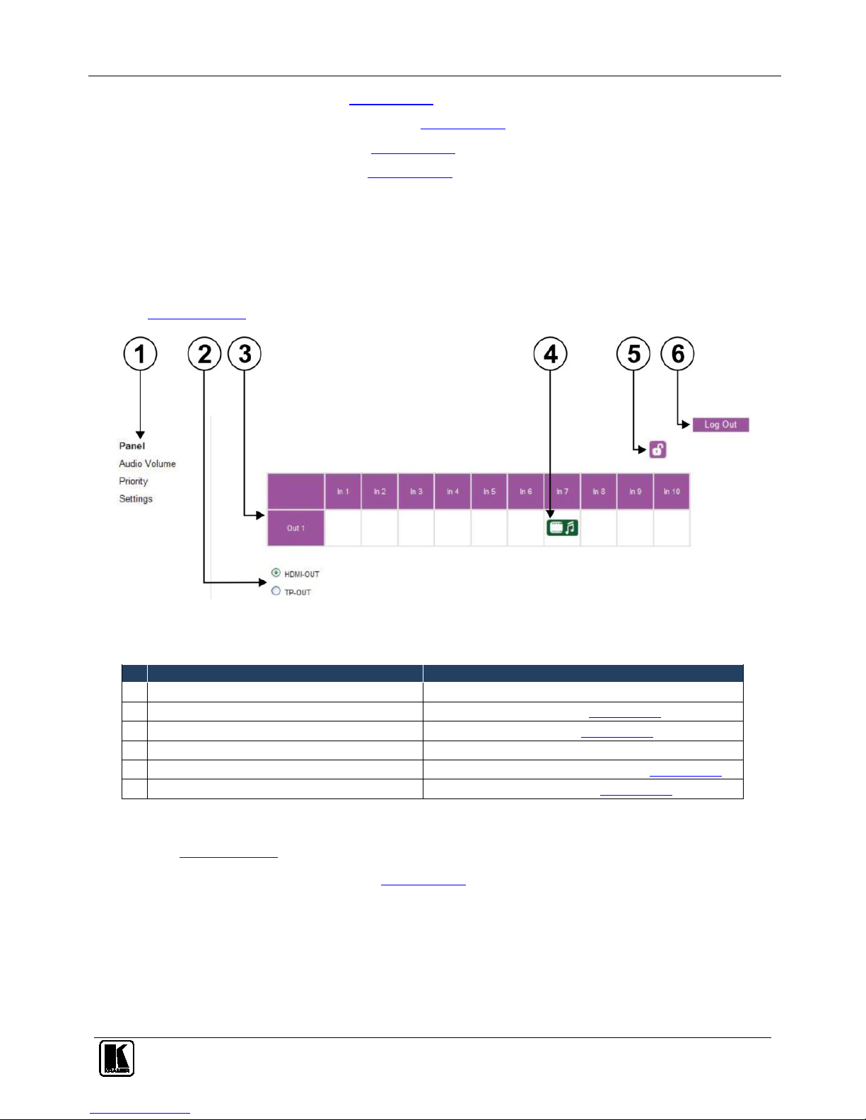
The VP-81SID Panel page lets you perform operational actions, such as, switching
inputs/outputs and locking the front panel buttons.
Note: Options that are grayed out indicate insufficient user privileges (see
Section 9.2.1
).
Figure 21: VP-81SID Panel Page
Table 7: VP-81SID Panel Page Features
#
Feature
Function
1 Page Name Indicates the current page
2 Output Radio Buttons (HDMI and Twisted Pair) Click to select an output (see Section 9.2.2)
3 Input Selection (In 1 to In 10) Click to select an input (see Section 9.2.2)
4 Currently Selected Input Indicates the currently selected input
5 Lock Button Click to lock the front panel buttons (see Section 9.2.4)
6 Log In/Log Out Button Click to log on and log out (see Section 9.2.1)
9.2.1 Logging In to the Software
See Section 8.1.1 for a description of authorized users.
When security is disabled (see Section 9.5), no user authentication is performed
and all options are available for modification. When security is enabled,
authentication is by User or Admin privileges and some options have restricted
access.
Page 36
KRAMER: SIMPLE CREATIVE TECHNOLOGY
Operating the VP-81SID Remotely via the Embedded Web Pages
32
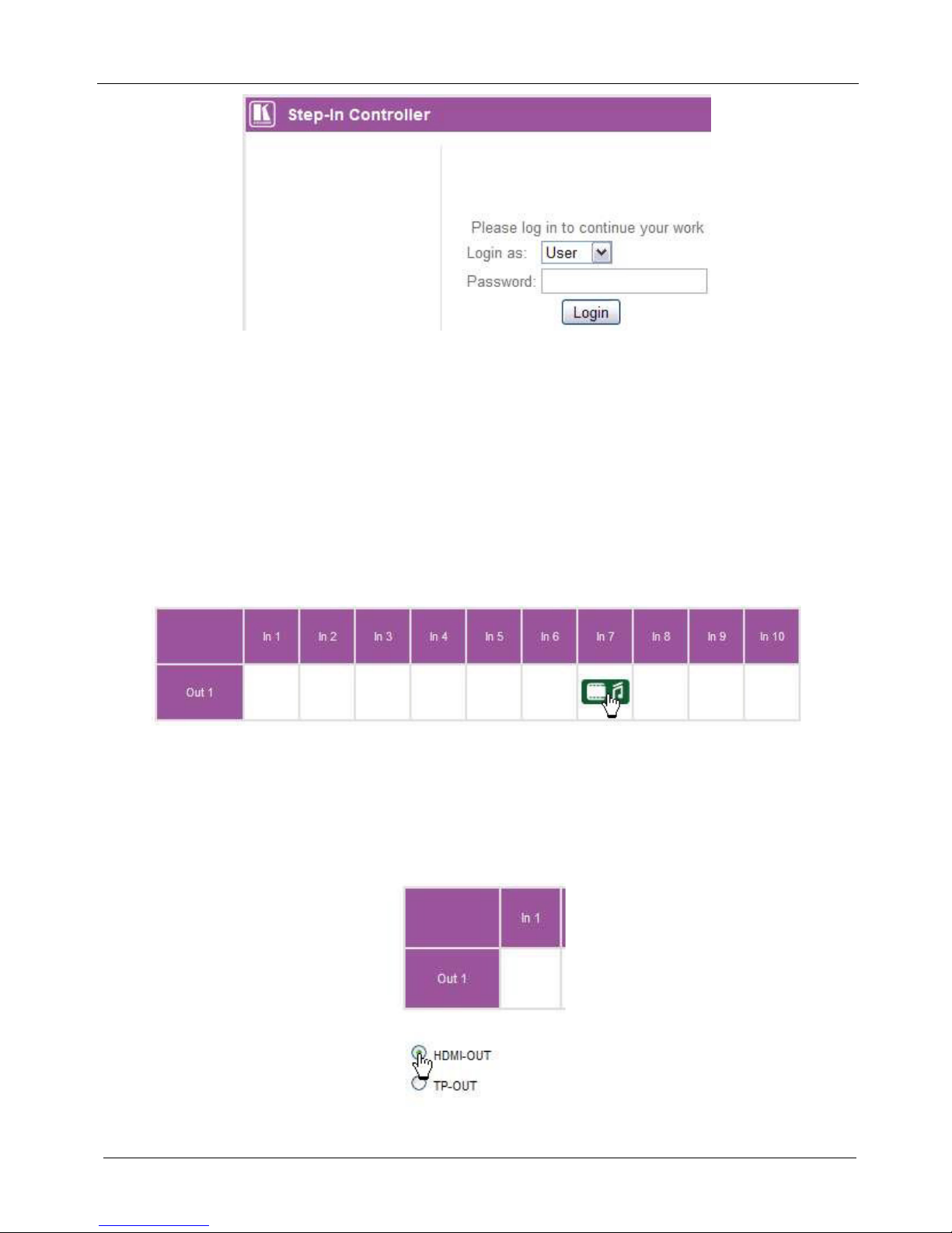
Figure 22: Logging In
To log in:
1. From the Login as drop-down list, select either User or Admin.
2. In the Password field enter your password.
3. Click Login.
9.2.2 Selecting an Input
To select an input:
• Click in the square underneath the required Input.
The selected input icon is placed in the square and the input becomes active.
Figure 23: Selecting an Input
9.2.3 Selecting an Output
To select an output:
• Click the radio button of the required Output.
The selected output becomes active.
Figure 24: Selecting an Output
Page 37
Operating the VP-81SID Remotely via the Embedded Web Pages
33
9.2.4 Locking the Front Panel Buttons
To lock the front panel buttons:
• Click on the lock icon.
The front panel buttons are locked. To unlock the front panel buttons, click
on the lock icon again
Figure 25: Locking the Front Panel Buttons
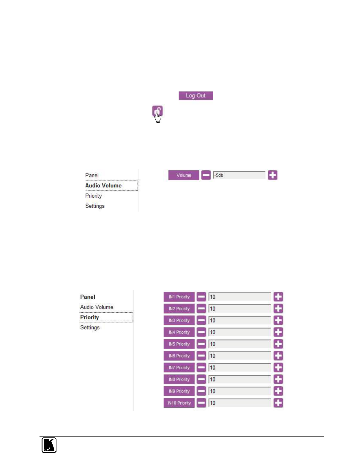
9.3 The VP-81SID Audio Volume Page
The VP-81SID Audio Volume page lets you adjust the audio output volume.
Figure 26: VP-81SID Audio Volume Page
To change the volume of the audio output:
• Click on the + (to increase) or on the – (to decrease) button of the Output
Volume
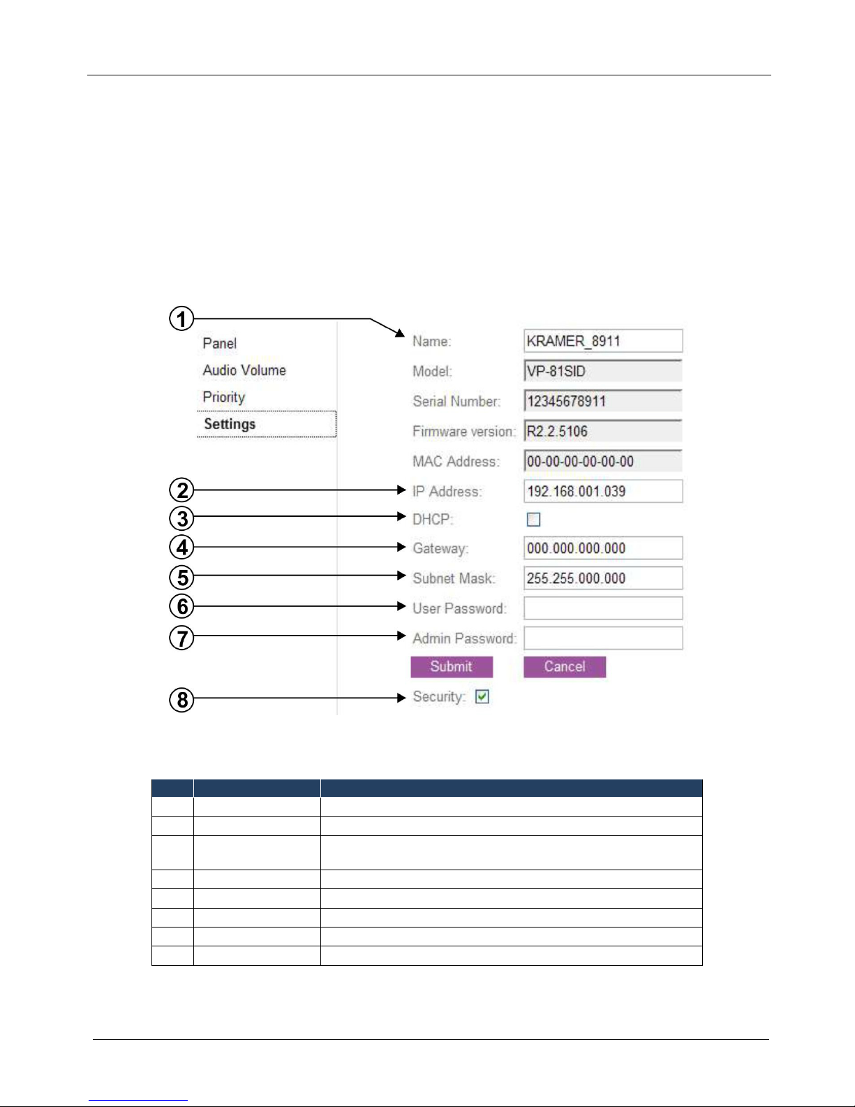
9.4 The VP-81SID Priority Page
The VP-81SID Priority page lets you set the input priority.
Figure 27: VP-81SID Priority Page
Page 38
KRAMER: SIMPLE CREATIVE TECHNOLOGY
Operating the VP-81SID Remotely via the Embedded Web Pages
34
To change the priority of an input:
• Click on the + (to increase) or on the – (to decrease) button of the input
whose priority you want to modify
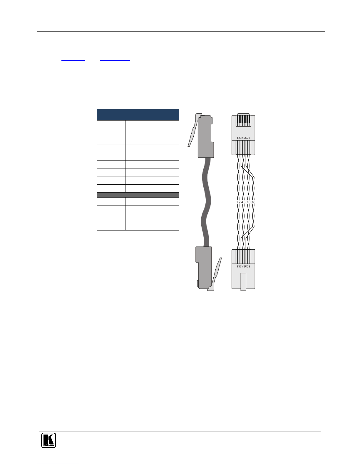
9.5 The VP-81SID Settings Page
The VP-81SID Settings page lets you configure the device configuration settings,
such as, device name and IP settings.
Note: Throughout this section options that are not available for an unauthorized
user are grayed out.
Figure 28: VP-81SID Settings Page
Table 8: VP-81SID Settings Page Features
#
Feature
Function
1 Name The name of the device
2 IP Address The IP address of the device
3 DHCP Check the box to configure the device to request an IP address from
a DHCP server
4 Gateway The gateway address of the device
5 Subnet Mask The subnet mask of the device
6 User Password The User password of the device
7 Admin Password The Admin password of the device
8 Security Check the box to enable User/Admin security
Page 39
Wiring the TP RJ-45 Connectors
35
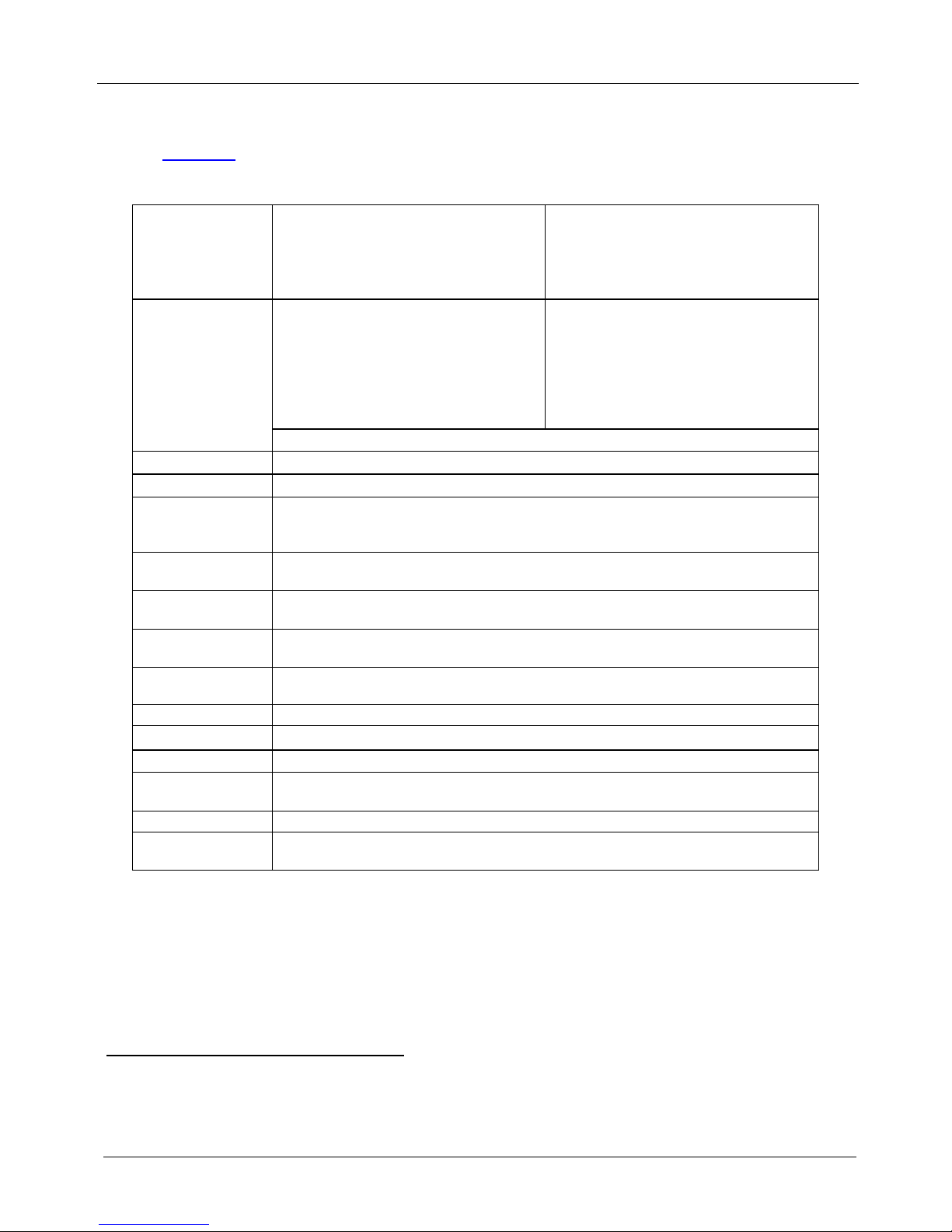
10 Wiring the TP RJ-45 Connectors
Table 9 and Figure 29 define the TP pinout, using a straight pin-to-pin cable with
RJ-45 connectors (note that the cable Ground shielding must be
connected/soldered to the connector shield).
Table 9: TP PINOUT
Figure 29: TP Pinout
Wiring
EIA /TIA 568B
PIN
PIN
1 Orange / White
2 Orange
3 Green / White
4 Blue
5 Blue / White
6 Green
7 Brown / White
8 Brown
Pair 1 4 and 5
Pair 2 1 and 2
Pair 3 3 and 6
Pair 4 7 and 8
Page 40
KRAMER: SIMPLE CREATIVE TECHNOLOGY
Technical Specifications
36
11 Technical Specifications
Table 10 lists the technical specifications1 of the VP-81SID.
Table 10: Technical Specifications of the VP-81SID
INPUTS: Video:
8 TP on RJ-45 connectors
1 DVI-D, 1.2Vpp on a DVI Molex 24-pin (F)
connector; DDC signal 5Vpp (TTL)
1 HDMI connector
Audio:
2 Unbalanced stereo audio (1 for DVI and 1
for HDMI) on 3.5mm mini jacks
OUTPUTS: Video:
1 TP on an RJ-45 connector
1 HDMI connector
Audio:
1 balanced stereo audio on a 5-pin
detachable terminal block
1 unbalanced stereo audio on 2 RCA
connectors
1 digital audio on an RCA connector
USB Power: 5V DC USB power
BANDWIDTH: 1.65Gbps per channel
STANDARDS: HDMI with Deep Color, x.v.Color™ and 3D
STEP-IN
COMMANDER
DISTANCE:
50m (164ft) up to 1080p @60Hz
OUTPUT
DISTANCE:
50m (164ft) up to 1080p @60Hz
POWER
CONSUMPTION:
100-240V AC 50/60Hz 70VA
OPERATING
TEMPERATURE:
0° to +55°C (32° to 131°F)
STORAGE
TEMPERATURE:
-45° to +72°C (-49° to 162°F)
HUMIDITY: 10% to 90%, RHL non-condensing
DIMENSIONS: 43.7cm x 18.1cm x 4.4cm (17.2” x 7.1” x 1.7”) W, D, H rack-mountable
WEIGHT: 2.0kg (4.4lbs) approx.
ACCESSORIES: Power cord, Windows®-based Kramer control software, RC-IR3 Infrared Remote Control
transmitter
OPTIONS: External remote IR receiver cable2; 15m extension cable3
REMOTE STEP-IN
SWITCHES
SID-VGA, SID-DP, SID-DVI, SID-H, SID-X1
1 Specifications are subject to change without notice
2 P/N: C-A35M/IRR-50
3 P/N: C-A35M/A35F-50
Page 41
Default Communication Parameters
37
12 Default Communication Parameters
Table 11 lists the default communication parameters for the VP-81SID.
Table 11: Communication Parameters
RS-232
Protocol 3000
Baud Rate: 115200
Data Bits: 8
Stop Bits: 1
Parity: None
Command Format: ASCII
Example (Output 2 to Input 4): #AV 4>2<CR>
Factory Default Ethernet Values
To reset the IP settings to the factory reset values, power cycle the device while holding in the
Factory Reset button, located on the rear panel of the unit
IP Address: 192.168.1.39
Subnet mask: 255.255.255.0
Default gateway: 192.168.1.1
TCP Port #: 5000 5000
UDP Port #: 50000 50000
Maximum UDP Ports: 10
Maximum TCP Ports: 4
13 Default EDID
Each input on the VP-81SID is loaded with an EDID detected on output. If no
output EDID is detected, factory default will be used.
Monitor
Model name............... VP-81SID
Manufacturer Name = KRM
Product Code = 4608
Serial Number = 16843009
Week of Manufacture = 255
Year of Manufacture = 2011
EDID Version = 1.3
--- Video Input Definition --Signal Type = Digital
DFP 1.x = Not Compatible
--- Basic Display Parameters --Max Horizontal Size(cm) = 52
Max Vertical Size(cm) = 32
Gamma Value = 2.20
--- Display Features --Standby Mode = Supported
Suspend Mode = Supported
Active Off Mode = Supported
Display Type = RGB
Color Space = Alternate
Preferred Timing = 1st Detail
GTF Timing = Not Supported
--- Color Characteristics --Red x = 0.674
Red y = 0.318
Page 42

KRAMER: SIMPLE CREATIVE TECHNOLOGY
Default EDID
38
Green x = 0.188
Green y = 0.705
Blue x = 0.148
Blue y = 0.064
White x = 0.313
White y = 0.328
--- Established Timing I --[v]720x400@70 [v]720x400@88
[v]640x480@60 [v]640x480@67
[v]640x480@72 [v]640x480@75
[v]800x600@56 [v]800x600@60
--- Established Timing II --[v]800x600@72 [v]800x600@75
[v]832x624@75 [v]1024x768@87
[v]1024x7680@60 [v]1024x7680@70
[v]1024x7680@75 [v]1280x1024@75
--- Manufacturer Timing --[v]1152x870@75
--- Standard Timing 1 --Horizontal Active Pixel = 1280
Vertical Active Pixel = 1024
Image Aspect Ratio = 5:4
Refresh Rate = 75
--- Standard Timing 2 --Horizontal Active Pixel = 1280
Vertical Active Pixel = 1024
Image Aspect Ratio = 5:4
Refresh Rate = 85
--- Standard Timing 3 --Horizontal Active Pixel = 1600
Vertical Active Pixel = 1200
Image Aspect Ratio = 4:3
Refresh Rate = 60
--- Standard Timing 4 --Horizontal Active Pixel = 1024
Vertical Active Pixel = 768
Image Aspect Ratio = 4:3
Refresh Rate = 85
--- Standard Timing 5 --Horizontal Active Pixel = 800
Vertical Active Pixel = 600
Image Aspect Ratio = 4:3
Refresh Rate = 85
--- Standard Timing 6 --Horizontal Active Pixel = 640
Vertical Active Pixel = 480
Image Aspect Ratio = 4:3
Refresh Rate = 85
--- Standard Timing 7 --Horizontal Active Pixel = 1152
Vertical Active Pixel = 864
Image Aspect Ratio = 4:3
Refresh Rate = 70
--- Standard Timing 8 --Horizontal Active Pixel = 1280
Vertical Active Pixel = 960
Image Aspect Ratio = 4:3
Refresh Rate = 60
*** Detail Timings/Monitor Descriptors ***
--- BK0.Detail Timing1 ---
Page 43

Default EDID
39
Pixel Clock(MHz) = 74.250
H/V Active = 1280 / 720
H/V Blanking = 370 / 30
H/V Sync Offset = 110 / 5
H/V Sync Width = 40 / 5
H/V Image Size(mm) = 519 / 324
Scanning Mode = Non interlace
Stereo = Normal display no stereo
Sync Type = Digital Seperate
H/V Sync Polarity = Positve/Positive
Monitor Serial Number = 505-709990100
Monitor Name = VP81_SID
--- Monitor Range Limits --Min Vertical Rate = 56 Hz
Max Vertical Rate = 76 Hz
Mn Horizontal Rate = 30 KHz
Max Horizontal Rate = 83 KHz
Max Pixel Clock Rate = 170 MHz
2nd Timing Formula = Not supported
--- DTV Monitor Support --Block Tag = 2, CEA 861 Extension
Revision = 3
Underscan = Not Supported
Basic Audio = Supported
RGB/YCbCr444 = Supported
RGB/YCbCr422 = Supported
Native Format Number = 1
--- Audio Data Block --Audio Format = Linear PCM
Sampling Rate(KHz) = 32/44.1/48/96/192
Max number of channels = 8
Bit per Sample(bit) = 16/20/24
--- Video Data Block --1920x1080p 59/60 16:9 is Native
1280x720p 59/60 16:9
720x480p 59/60 16:9
720x576p 50 16:9
640x480p 59/60 4:3
1280x720p 50 16:9
720x576p 50 4:3
1440x480i 59/60 16:9
1920x1080i 59/60 16:9
1440x480i 59/60 4:3
1920x1080p 29/30 16:9
1920x1080i 50 16:9
1440x576i 50 4:3
--- Vendor Specific Data Block --VSDB block size = 6
IEEE Registration Id = 0x000C03
CEC Physical Address A.B.C.D =
1 . 0 . 0 . 0
Supports_AI = Supported
Deep Color(bit) = Not Supported
YCbCr444 Deep Color = Not Supported
DVI Dual Link = Not Supported
--- Speaker Allocation Data Block --Speaker Allocation =
FL/FR LFE FC RL/RR RLC/RRC
--- BK1.Detail Timing1 --Pixel Clock(MHz) = 74.250
H/V Active = 1280 / 720
H/V Blanking = 370 / 30
Page 44

KRAMER: SIMPLE CREATIVE TECHNOLOGY
Default EDID
40
H/V Sync Offset = 110 / 5
H/V Sync Width = 40 / 5
H/V Image Size(mm) = 488 / 274
Scanning Mode = Non interlace
Stereo = Normal display no stereo
Sync Type = Digital Seperate
H/V Sync Polarity = Positve/Positive
--- BK1.Detail Timing2 --Pixel Clock(MHz) = 27.000
H/V Active = 720 / 576
H/V Blanking = 144 / 49
H/V Sync Offset = 12 / 5
H/V Sync Width = 64 / 5
H/V Image Size(mm) = 488 / 274
Scanning Mode = Non interlace
Stereo = Normal display no stereo
Sync Type = Digital Seperate
H/V Sync Polarity = Negative/Negative
--- BK1.Detail Timing3 --Pixel Clock(MHz) = 27.000
H/V Active = 720 / 480
H/V Blanking = 138 / 45
H/V Sync Offset = 16 / 9
H/V Sync Width = 62 / 6
H/V Image Size(mm) = 488 / 274
Scanning Mode = Non interlace
Stereo = Normal display no stereo
Sync Type = Digital Seperate
H/V Sync Polarity = Negative/Negative
--- BK1.Detail Timing4 --Pixel Clock(MHz) = 74.250
H/V Active = 1920 / 540
H/V Blanking = 280 / 22
H/V Sync Offset = 88 / 2
H/V Sync Width = 40 / 5
H/V Image Size(mm) = 488 / 274
Scanning Mode = Interlace
Stereo = Normal display no stereo
Sync Type = Digital Seperate
H/V Sync Polarity = Negative/Negative
--- BK1.Detail Timing5 --Pixel Clock(MHz) = 74.250
H/V Active = 1280 / 720
H/V Blanking = 700 / 30
H/V Sync Offset = 440 / 5
H/V Sync Width = 40 / 5
H/V Image Size(mm) = 488 / 274
Scanning Mode = Non interlace
Stereo = Normal display no stereo
Sync Type = Digital Seperate
H/V Sync Polarity = Positve/Positive
Raw Data
02 03 21 71 4D 90 04 03 //87 12 01 13 11 07 05 06 22 //8F 14 15 23 0F 57 07 83 4F //97 00 00 66 03 0C 00 10 00 //9F
80 01 1D 00 72 51 D0 1E //A7 20 6E 28 55 00 E8 12 11 //AF 00 00 1E 8C 0A D0 90 20 //B7 40 31 20 0C 40 55 00 E8
//BF 12 11 00 00 18 8C 0A D0 //C7 8A 20 E0 2D 10 10 3E 96 //CF 00 E8 12 11 00 00 18 01 //D7 1D 80 18 71 1C 16 20
58 //DF 28 25 00 E8 12 11 00 00 //E7 98 01 1D 00 BC 52 D0 1E //EF 20 B8 28 55 40 E8 12 11 //F7 00 00 1E 00 00 00
00 4F //FF
Page 45
Protocol 3000 Syntax
41
14 Protocol 3000 Syntax
The Kramer Protocol 3000 lets you control the device from any standard terminal
software (for example, the Windows® HyperTerminal Application).
14.1 Host Message Format
Start Address (optional) Body Delimiter
#
device_id@
Message
CR
14.2 Simple Command
Command string with only one command without addressing.
Start Body Delimiter
#
Command SP Parameter_1,Parameter_2,… CR
14.3 Command String
Formal syntax with commands concatenation and addressing.
Start
Address Body Delimiter
#
device_id@
Command_1
Parameter1_1,Parameter1_2,…|
Command_2
Parameter2_1,Parameter2_2,…|
Command_3
Parameter3_1,Parameter3_2,…|…
CR
14.4 Device Message Format
Start
Address
(optional)
Body delimiter
~
device_id@
Message CR LF
14.5 Device Long Response
Echoing command.
Start
Address
(optional)
Body Delimiter
~
device_id@
Command SP [Param1
,Param2 …] result
CR LF
CR = Carriage return (ASCII 13 = 0x0D)
LF = Line feed (ASCII 10 = 0x0A)
SP = Space (ASCII 32 = 0x20)
Page 46

KRAMER: SIMPLE CREATIVE TECHNOLOGY
Protocol 3000 Syntax
42
14.6 Command Terms
Command
A sequence of ASCII letters ('A'-'Z', 'a'-'z' and '-').
Command and parameters must be separated by at least one space.
Parameters
A sequence of alphameric ASCII characters ('0'-'9','A'-'Z','a'-'z' and some special
characters for specific commands). Parameters are separated by commas.
Message string
Every command entered as part of a message string begins with a message
starting character and ends with a message closing character.
Note: A string can contain more than one command. Commands are separated by a
pipe ( '|' ) character.
Message starting character
'#' – For host command/query
'~' – For machine response or machine command performed by keystroke operation
on the front panel or IR remote controller.
Device ID (Optional when directly connected to the device)
K-NET Device ID or MACHINE NUMBER followed by '@'
(ex. #02@
CRLF )
Query sign
'?' follows some commands to define a query request.
All outputs sign
'*' defines all outputs.
Message closing character
CR – For host messages; carriage return (ASCII 13)
CRLF – For machine messages; carriage return (ASCII 13) + line-feed (ASCII 10)
Command chain separator character
When a message string contains more than one command, a pipe ( '|' ) character
separates each command.
Spaces between parameters or command terms are ignored.
14.7 Entering Commands
You can directly enter all commands using a terminal with ASCII communications
software, such as HyperTerminal, Hercules, etc. Connect the terminal to the serial,
Ethernet, or USB port on the Kramer device. To enter
CR , press the Enter key.
( LF is also sent but is ignored by command parser).
For commands sent from some non-Kramer controllers like Crestron, some
characters require special coding (such as, /X##). Refer to the controller manual.
Page 47
Protocol 3000 Syntax
43
14.8 Bi-directional definition
All commands are bi-directional. That is, if the device receives the code, it will
perform the instruction; and if the instruction is performed (due to a keystroke
operation on the front panel or IR controller), then these codes are sent to the PC or
other RS-232 / Ethernet / USB controller.
14.9 Command Forms
Some commands have short name syntax in addition to long name syntax to allow
faster typing. The response is always in long syntax.
14.10 Command Chaining
Multiple commands can be chained in the same string. Each command is delimited
by a pipe character ( '|' ). When chaining commands, enter the message starting
character and the message closing character only once, at the beginning of the
string and at the end.
Commands in the string do not execute until the closing character is entered.
A separate response is sent for every command in the chain.
14.11 Maximum String Length
64 characters
14.12 Backward Support
The VP-81SID supports the commands listed in
Table 12
.
Table 12: Communication Commands
Command Parameters Description
#
Protocol handshaking
MODEL?
Read device model
VERSION?
Read device firmware version
SN?
Read device serial number
NAME?
Get device name
MACH-NUM
Set the machine num
BUILD-DATE?
Read device build date
PROT-VER?
Read device protocol version
HELP
List of commands
RESET
Reset device
LDFW
Load firmware file – by application only
LDFPGA
Load FPGA binary file – by application only
LOCK-FP
1/0 (1=lock on,0=lock off)
Set lock for front panel
LOCK-FP?
Get lock state
NET-IP
Set IP address
NET-IP?
Get IP address
Page 48
KRAMER: SIMPLE CREATIVE TECHNOLOGY
Protocol 3000 Syntax
44
SET Commands
AV/V/ VID
in>out Set current <input> and <output>
VOLUME, VOL
-63db to 0db, or +/- chars
(exp: VOL +, VOLUME -)
Set Volume
PRIO
input, priority
Set priority [1..10] to input [1..10]
MUTE
1/0 (1=mute on,0=mute
off)
Set audio mute for device
IREN
Enable/Disable IR driver
VID-TYPE
input, sid-x1 input Switch inputs on SID-X1 via VP-81SID (as
described in Section
8.1.6)
GET Commands
AV?/V?/VID?
out
Get current input-to-output routing setting
VOLUME?/ VOL?
Get Volume
MUTE?
Get audio mute state
VID-RES?
Stage (in\
out), num
Get input video resolution
VID-TYPE?
Stage (in\out), num
Get input video type
IN-STATE?
In
Get input information for <input [1..10]> ->
GEDID?
Stage (in/out), num
Clock [ON/OFF], State [TOUT/ACT/MUTE],
Priority [0..11]
FPGA-VER?
Id
Get EDID info for stage [in/out]
IREN?
Get FPGA version
14.12.1 #
Command Name Short
Cmd
Command Type Permission
#
Common-mandatory
End User
Protocol handshaking
Syntax
#␍
Response
~nn@␠OK␍␊
Param ete rs
Notes
Use to validate protocol 3000 connection and to get machine number.
Page 49
Protocol 3000 Syntax
45
14.12.2 MODEL?
Command Name Short Cmd Command Type Permission
MODEL?
Common-ma nd at ory
End User
Read device model
Syntax
#MODEL?␍
Response
~nn@MODEL␠model_name␍␊
Param ete rs
model_name – String of printable ASCII chars (up to 19 chars).
Notes
14.12.3 VERSION?
Command Name Short Cmd Command Type Permission
VERSION?
Common-ma nd at ory
End User
Reset device serial number
Syntax
#VERSION?␍
Response
~nn@VERSION␠firmware_version␍␊
Param ete rs
firmware_version – Format: XX.XX.XX.XXXX where the digits group are: Major.Minor.Build.Revision
Notes
Page 50
KRAMER: SIMPLE CREATIVE TECHNOLOGY
Protocol 3000 Syntax
46
14.12.4 SN?
Command Name Short Cmd Command Type Permission
SN?
Common-ma nd at ory
End User
Reset device serial number
Syntax
#SN?␍
Response
~nn@SN␠serial_number␍␊
Param ete rs
serial_number – 11 decimal digits. Assign by Kramer factory.
Notes
For new products with 14 digits serial we kept only the last 11.
14.12.5 NAME?
Command Name Short Cmd Command Type Permission
NAME?
Common (Ethernet )
End User
Get machine (DNS) name
Syntax
#NAME?␍
Response
~nn@NAME␠machine_name␍␊
Param ete rs
machine_name – String of up to 14 alpha-numeric chars (can include hyp hen, not in beginning or end).
Notes
The machine name is not the same as the model name. The machine name is used to identify a specific machine or a network in
use (with DNS feature on).
Page 51
Protocol 3000 Syntax
47
14.12.6 MACH-NUM
Command Name Short Cmd Command Type Permission
MACH-NUM
Common
End User
Set Machine number
Syntax
#MACH-NUM␠machine_number␍
Response
~nn@MACH-NUM␠machine_number OK␍␊
Param ete rs
machine_number – New machine number to device
Notes
Some devices will not get the new machine number until restart the device.
Some devices can change machine number only from dip-switches
14.12.7 BUILD-DATE?
Command Name Short
Cmd
Command Type Permission
#BUILD-DATE?␍
Response
~nn@BUILD-DATE␠date␠time␍␊
Param ete rs
date – Format: YYYY/MM/DD where YYYY = Year. MM = Month. DD = Day.
time – Format: hh:mm:ss where hh = hours. mm = minutes. ss = secondes.
Notes
Page 52
KRAMER: SIMPLE CREATIVE TECHNOLOGY
Protocol 3000 Syntax
48
14.12.8 PROT-VER?
Command Name Short Cmd Command Type Permission
PROT-VER?
Common-ma nd at ory
End User
Read device model
Syntax
#PROT-VER?␍
Response
~nn@PROT-VER␠3000:version␍␊
Param ete rs
Version – Format: XX.XX where X is decimal digits.
Notes
Version number need to reference to version of “Protocol 3000 Extended” document.
14.12.9 HELP
Command Name
Short Cmd
Command Type
Permission
HELP
Common-mandatory
End User
Get commands list or help for specific command
Syntax
2 options:
1. #HELP␍
2. #HELP␠command_name␍
Response
1. Multi-line: ~nn@Device available protocol 3000 commands:␍␊command,␠command…␍␊To get help for
command use : HELP (COMMAND_NAME)␍␊
2. Multi-line: ~nn@HELP␠command:␍␊description␍␊USAGE:usage ␍␊
Parameters
Notes
Page 53
Protocol 3000 Syntax
49
14.12.10 RESET
Command Name Short Cmd Command Type Permission
RESET
Common-ma nd at ory
Administrator
Reset device
Syntax
#RESET␍
Response
~nn@RESET␠OK␍␊
Param ete rs
Notes
If device connected by USB, it’s recommend to disconnect the connection immediately after operating this command, to
eliminate port locking because USB bug in windows (if port was locked anyway, disconnect and reconnect the cable and then
try to open port again).
14.12.11 LDFW
Command Name Short Cmd Command Type Permission
LDFW
Common - Packets
Admin
Load new Firmware file
Syntax
Step 1: #LDFW␠size␍
Response 1: ~nn@LDFW␠ size␠READY␍␊ or ~nn@LDFW␠ERRnn␍␊
Step 2: If ready was received, send FIRMWARE_DATA P
Response 2: ~nn@LDFW␠size␠OK␍␊
Param ete rs
size –Size of firmware data that will send.
FIRMWARE_DATA - HEX or KFW file in protocol packets (Apendix A)
Notes
In most devices firmware data will saved to device flash memory, but device will not update until receiving command
“UPGRADE” and restart.
P
Protocol Packet reference: Appendix A.
Page 54
KRAMER: SIMPLE CREATIVE TECHNOLOGY
Protocol 3000 Syntax
50
14.12.12 LDFPGA
Command Name Short Cmd Command Type Permission
LDFPGA
Common - Packets
Admin
Load new FPGA file
Syntax
Step 1: #LDFPGA␠size␠CRC␠ID␠ CRC_Check␍
Response 1: ~nn@LDFPGA␠ READY␍␊ or ~nn@LDFW␠ERRnn␍␊
Step 2: If ready was received, send FPGA_DATA P
Response 2: ~nn@LDFPGA␠size␠OK␍␊
Param ete rs
size –Size of firmware data that will send.
CRC – FPGA CRC
ID – FPGA ID (if there are more than one FPGA in Device, 1 –otherwise)
CR_Check – if CRC test needed flag
FPGA_DATA - HEX or KFW file in protocol packets
Notes
P
Protocol Packet reference: Appendix A.
14.12.13 LOCK-FP
Command Name Short Cmd Command Type Permission
LOCK-FP
Common
End User
Lock front panel
Syntax
Option 1: #LOCK-FP␠lock_mode␍
Option 2: #LOCK-FP␠device_id, lock_mode␍
Response
Option 1: ~nn@LOCK-FP␠lock_mode␠OK␍␊
Option 2: ~01@LOCK-FP␠device_id,lock_mode␠OK␍␊
Param ete rs
lock_mode – ‘0’ or ‘off’ to unlock front panel buttons. ‘1’ or ‘on’ to lock front panel buttons.
device_id – For K-Net controllers, select the but tons panel to lock. Locking is allowed only from the master.
Notes
Page 55
Protocol 3000 Syntax
51
14.12.14 LOCK-FP?
Command Name Short Cmd Command Type Permission
LOCK-FP?
Common
End User
Get lock state of front panel
Syntax
Option 1: #LOCK-FP?␍
Option 2: #LOCK-FP?␠device_id␍
Response
Option 1: ~nn@LOCK-FP␠lock_mode␍␊
Option 2: ~01@LOCK-FP␠device_id, lock_mode␍␊
Param ete rs
lock_mode – ‘OFF’ for unlocked front panel. ‘ON’ for locked front panel.
device_id – For K-Net controllers, select the buttons panel to get lock state. State is available only from the master.
Notes
14.12.15 NET-IP
Command Name Short Cmd Command Type Permission
NET-IP
NTIP Ethernet
Administrator
Set device IP address
Syntax
#NET-IP␠ ip_address ␍
Response
~nn@ NET-IP ␠ ip_address ␠OK␍␊
Param ete rs
ip_address – format: xxx.xxx.xxx.xxx
Notes
For proper settings consult your network administrator
Page 56
KRAMER: SIMPLE CREATIVE TECHNOLOGY
Protocol 3000 Syntax
52
14.12.16 NET-IP?
Command Name Short Cmd Command Type Permission
NET-IP?
NTIP? Ethernet
End User
Get device IP address
Syntax
#NET-IP?␍
Response
~nn@ NET-IP ␠ ip_address ␍␊
Param ete rs
ip_address – format: xxx.xxx.xxx.xxx where x is decimal digit.
Notes
14.12.17 92BAV
Command Name Short Cmd Command Type Permission
AV
Switch
End User
Switch Audio and Video
Syntax
#AV␠in>out, in>out,…␍
Response
~nn@AV␠in>out, in>out,…␍␊
Param ete rs
In - input number or '0' to disconnect output
'>' = Connection character between in and out parameters
out = Output number or '*' for all outputs
Notes
Out = 1 (TP output)
Out = 2 (HDMI output)
Page 57
Protocol 3000 Syntax
53
14.12.18 VID
Command Name Short Cmd Command Type Permission
VID
V Switch
End User
Switch Video
Syntax
#VID␠in>out, in>out,…␍
Response
~nn@VID␠in>out ␍␊ ~nn@VID␠in>out ␍␊ …
Param ete rs
In - input number or '0' to disconnect output
'>' = Connection character between in and out parameters
out = Output number or '*' for all outputs
Notes
When AFV switching mode is active, this command also switches Audio and the unit replies with command ~AV.
14.12.19 VID?
Command Name Short Cmd Command Type Permission
VID?
V? Switch
End User
Get Video Switch Stat
Syntax
#VID?␠out␍
#VID?␠ * ␍
Response
~nn@VID␠ in>out ␍␊
~nn@VID␠ in>1 , in>2 , … ␍␊
Param ete rs
in - input number or '0' to disconnect output
'>' = Connection character between in and out parameters
out = Output number or '*' for all outputs
Notes
Page 58
KRAMER: SIMPLE CREATIVE TECHNOLOGY
Protocol 3000 Syntax
54
14.12.20 VOLUME
Command Name Short Cmd Command Type Permission
VOLUME
VOL Aud io
End User
Set simple audio vo lu me
Syntax
#VOLUME␠ out_channel, volume ␍
Response
~nn@VOLUME␠ out_ channel, volume ␍␊
Param ete rs
out_channel = Output #
volume = Audio parameter in Kramer units, minus sign precedes negative values.
++ increase current value,
-- decrease current value
Notes
For set / get “input” level or audio level in other amplifier stage use command #AUD-LVL / #AUD-LVL? – set / get audio
level in specific amp lifier stage
14.12.21 VOLUME?
Command Name Short Cmd Command Type Permission
VOLUME?
VOL? Audio
End User
Get simp le aud io volume
Syntax
#VOLUME?␠ out_channel ␍
Response
~nn@VOLUME␠ out_ channel, volume ␍␊
Param ete rs
out_channel = Output #
volume = Audio parameter in Kramer units, minus sign precedes negative values.
++ increase current value,
-- decrease current value
Notes
For set / get “input” level or audio level in other amplifier stage use command #AUD-LVL / #AUD-LVL? – set / get audio
level in specific amp lifier stage
Page 59
Protocol 3000 Syntax
55
14.12.22 PRIO
Command Name Short Cmd Command Type Permission
PRIO
Device specific Administrator
Syntax Response
PRIO INPUT , PRIORITY PRIO INPUT , PRIORITY OK
Description Notes
Set input Priority INPUT – 1…10
PRIORITY - 1..10
14.12.23 MUTE
Command Name Short Cmd Command Type Permission
MUTE
Audio
End User
Set audio MUTE mode
Syntax
#MUTE␠ channel, mute_mode ␍
Response
~nn@MUTE␠ channel, mute_mode ␍␊
Param ete rs
channel = Output #
mute_mode = ‘0’ or ‘OFF’ / ‘1’ or ‘ON’
Notes
Page 60
KRAMER: SIMPLE CREATIVE TECHNOLOGY
Protocol 3000 Syntax
56
14.12.24 MUTE?
Command Name Short Cmd Command Type Permission
MUTE?
Audio
End User
Get audio MUTE mode status
Syntax
#MUTE?␠ channel ␍
Response
~nn@MUTE␠ channel, mute_mode ␍␊
Param ete rs
channel = Output #
mute_mode = ‘0’ or ‘OFF’ / ‘1’ or ‘ON’
Notes
14.12.25 IREN
Command Name Short Cmd Command Type Permission
IREN
Common End User
Syntax Response
IREN 1/0 IREN 1/0 OK
Description Notes
Enable/ Disable IR control
1/0= On OR Off
14.12.26 VID-TYPE
Command Name Short Cmd Command Type Permission
VID-TYPE
Device specific End User
Syntax Response
VID-TYPE INPUT , SID-X1 INPUT VID-TYPE INPUT , INPUT TYPE , IS_X1_INPUT
Description Notes
Switch SID-X1 inputs remotely via VP-81SID INPUT - input No. of switcher, where HDMI=0, DP=1, DVI=2,
VGA=3
SID-X1 INPUT – input No. of SID-X1 to switch to
INPUT_TYPE – VGA / HDMI / DVI / DP
IS_X1_INPUT - 0/1 report if connected module is SID-X1 or not
Page 61
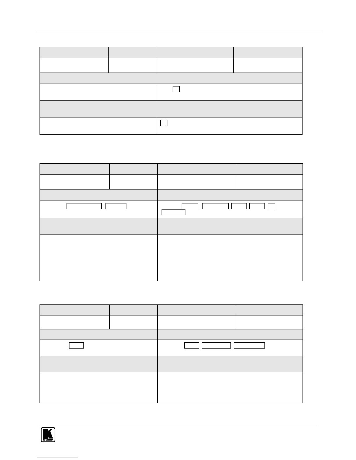
Protocol 3000 Syntax
57
14.12.27 IREN?
Command Name Short Cmd Command Type Permission
IREN?
Common End User
Syntax Response
IREN?
IREN 1/0
Description Notes
Get IR control current status
1/0= On OR Off
14.12.28 VID-RES?
Command Name Short Cmd Command Type Permission
VID-RES?
Device specific End User
Syntax Response
VID-RES? INPUT/OUTPUT , NUMBER VID-RES IN/OUT , INPUT NUM , HSIZE , VSIZE , I/P,
REF.RATE
Description Notes
Get input/output resolution information IN/OUT - stage input/output (string)
INPUT NUM– input (output) No.
HSIZE - pixel number
VSIZE – lines number
I/P - interlaced/ progressive
REF.RATE – refresh rate
14.12.29 VID-TYPE?
Command Name Short Cmd Command Type Permission
VID-TYPE?
Device specific End User
Syntax Response
VID-TYPE? INPUT VID-TYPE INPUT , INPUT TYPE , IS_X1_INPUT
Description Notes
Get current module type connected to switcher input INPUT - input No. of switcher
SID-X1 INPUT – input No. of SID-X1 to switch to
INPUT_TYPE – VGA / HDMI / DVI / DP
IS_X1_INPUT - 0/1 report if connected module is SID-X1 or not
Page 62
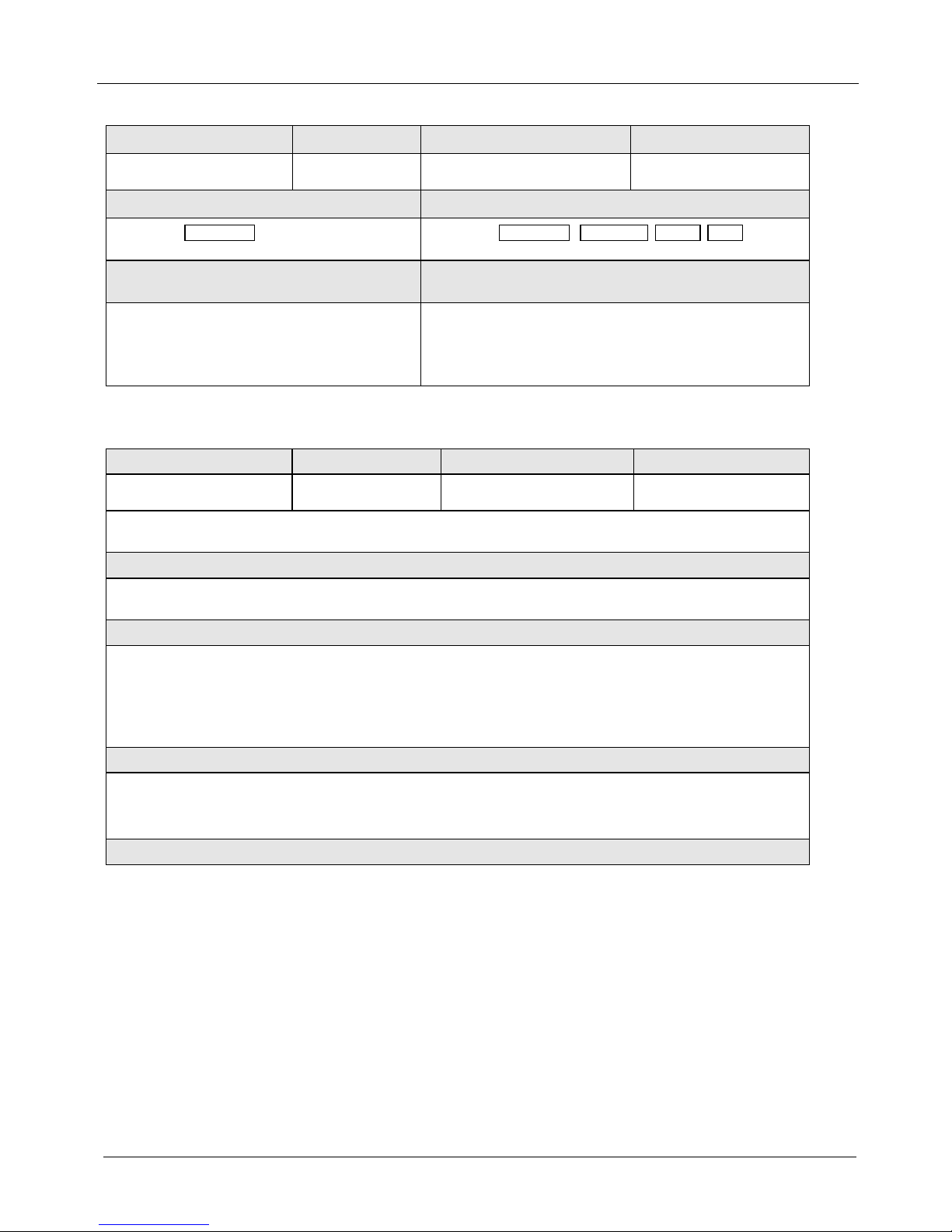
KRAMER: SIMPLE CREATIVE TECHNOLOGY
Protocol 3000 Syntax
58
14.12.30 IN-STATE?
Command Name Short Cmd Command Type Permission
IN-STATE?
Device specific End User
Syntax Response
IN-STATE? INPUT NUM IN-STATE? INPUT NUM , TMDS_CLK , STATE , PRIO
Description Notes
Get input status INPUT_NUM – input No.
TMDS_CLK - clock presence on input
STATE – MUTE / ACT (active)/ TOUT (timedouted)
PRIO - current priority
14.12.31 GEDID
Command Name Short Cmd Command Type Permission
GEDID
Common
End User
Read EDID data
Syntax
#GEDID␠eeprom_id␍
Response
Multi line response:
~nn@GEDID␠eeprom_id, size␍␊
Edid_data␍␊
~nn@GEDID␠eeprom_id ␠OK␍␊
Param ete rs
eeprom_id – EEPROM to get the EDID from
size – Device send this parameter in response. Size of EDID that will print.
edid_data – EDID data as stream of bytes.
Notes
Page 63
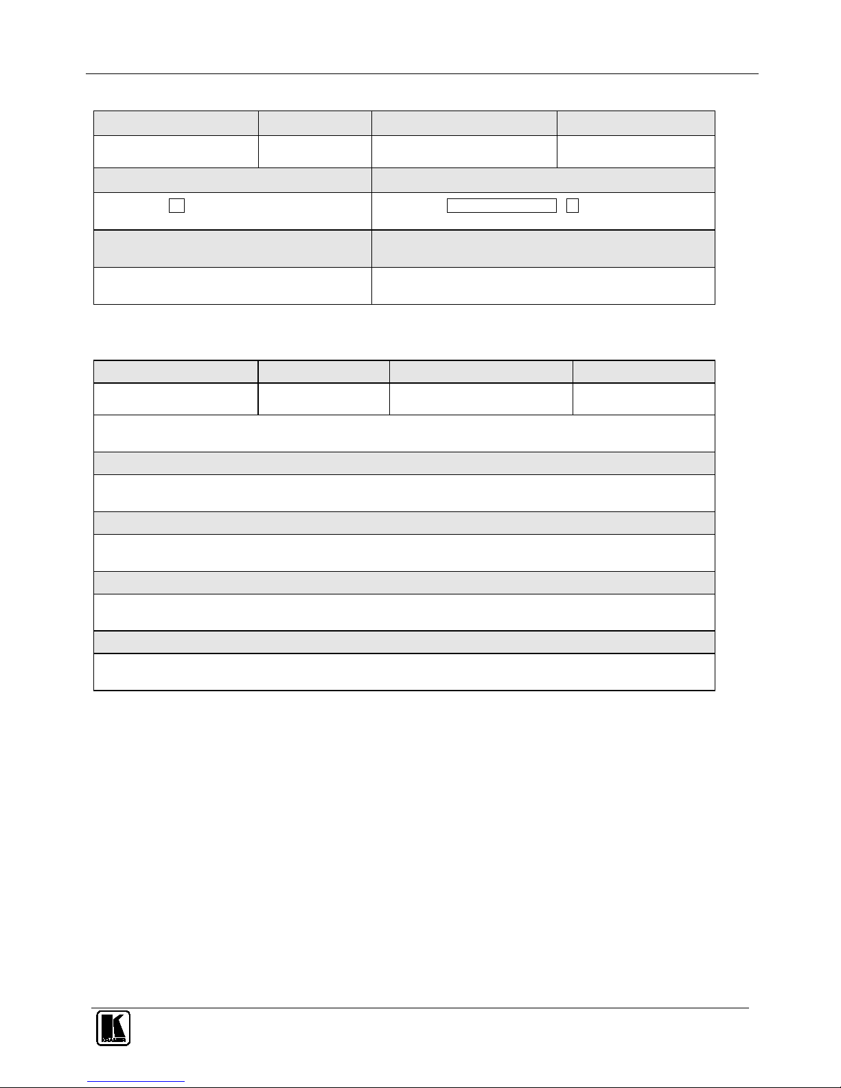
Protocol 3000 Syntax
59
14.12.32 FPGA-VER?
Command Name Short Cmd Command Type Permission
FPGA-VER? <?>
Device specific End User
Syntax Response
FPGA-VER? ID FPGA-VER? FPGA version number , ID
Description Notes
Request FPGA version by FPGA ID (optional)
14.12.33 SECUR
Command Name Short Cmd Command Type Permission
SECUR
Security
Administrator
Start/Stop security
Syntax
#SECUR␠security_mode␍
Response
~nn@SECUR␠security_mode ␠OK ␍␊
Param ete rs
security_mode – 1 or ON to enable security. 0 or OFF to disable security.
Notes
Permissions system work only if security was enabled (by “SECUR” command)
Page 64
KRAMER: SIMPLE CREATIVE TECHNOLOGY
Protocol 3000 Syntax
60
14.12.34 SECUR?
Command Name Short Cmd Command Type Permission
SECUR?
Security
Administrator
Get current security state
Syntax
#SECUR?␍
Response
~nn@SECUR␠security_mode␍␊
Param ete rs
security_mode –ON if security enabled. OFF if security disabled.
Notes
Permissions system work only if security was enabled (by “SECUR” command)
Page 65
61
Page 66

Kramer Electronics, Ltd.
Web site: www.kramerelectronics.com
E-mail: [email protected]
P/N: 2900-000750 REV 7
For the latest information on our products and a list of
Kramer distributors visit
www.kramerelectronics.com
where updates to this user manual may be found.
We welcome your questions, comments and feedback.
Caution
Safety Warning:
Disconnect the unit from the power supply before
opening/servicing.
P/N:
2900-000750
Rev:
7
 Loading...