

Page 1
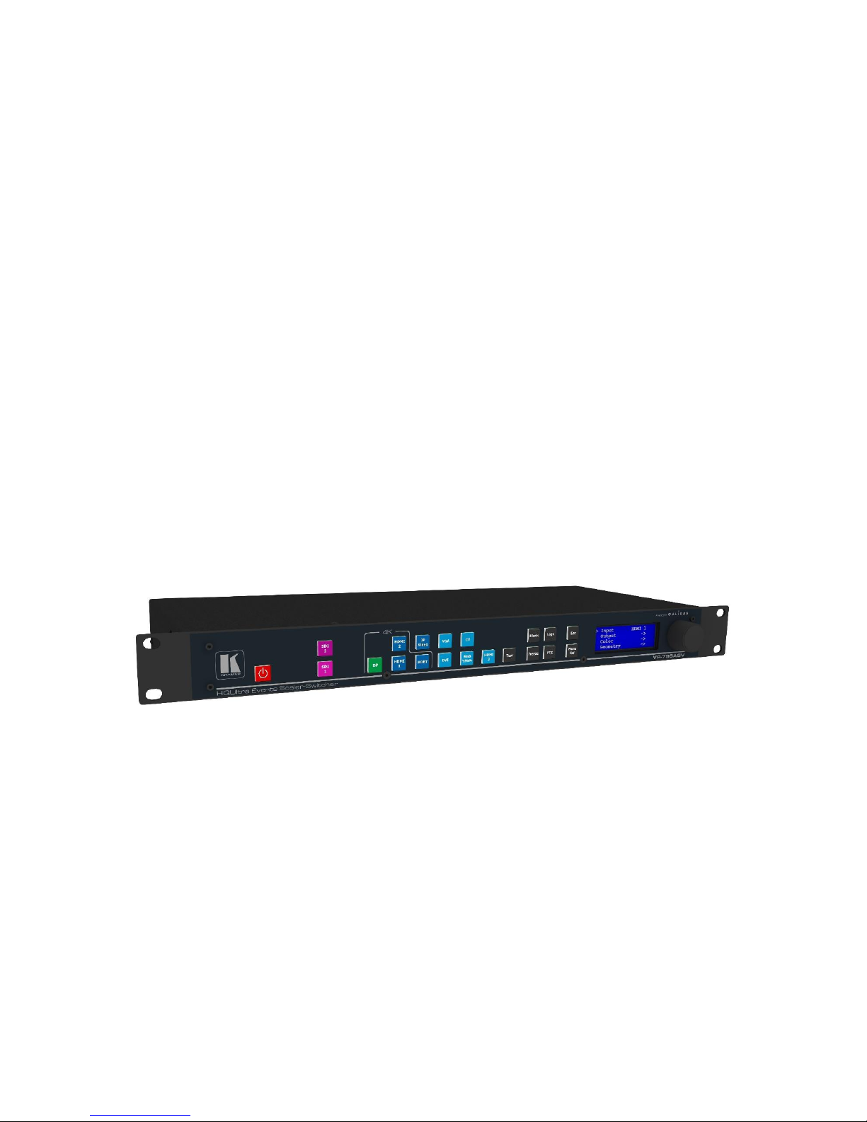
VP-796(A)(ASV) / VP-797A(ASV) / VP-798ASV
User’s Manual
Page 2

© KRAMER ELECTRONICS LTD.
Issue 1-16 May 30, 2017
2
COPYRIGHT
This document and the software described within it are copyrighted with all rights reserved. Under
copyright laws, neither the documentation nor the software may be copied, photocopied, reproduced,
translated, or reduced to electronic medium or machine readable form, in whole or in part, without
prior written consent of Kramer UK Ltd ("Kramer"). Failure to comply with this condition may result in
prosecution.
Kramer does not warrant that this product package will function properly in every hardware/software
environment.
Although Kramer has tested the hardware, firmware, software and reviewed the documentation,
KRAMER MAKES NO WARRANTY OR REPRESENTATION, EITHER EXPRESS OR IMPLIED, WITH RESPECT TO
THIS HARDWARE, FIRMWARE, SOFTWARE OR DOCUMENTATION, THEIR QUALITY, PERFORMANCE,
MERCHANTABILITY, OR FITNESS FOR A PARTICULAR PURPOSE. THIS SOFTWARE AND DOCUMENTATION
ARE LICENSED 'AS IS', AND YOU, THE LICENSEE, BY MAKING USE THEREOF, ARE ASSUMING THE ENTIRE
RISK AS TO THEIR QUALITY AND PERFORMANCE.
IN NO EVENT WILL KRAMER BE LIABLE FOR DIRECT, INDIRECT, SPECIAL, INCIDENTAL, OR
CONSEQUENTIAL DAMAGES ARISING OUT OF THE USE OR INABILITY TO USE THE SOFTWARE OR
DOCUMENTATION, even if advised of the possibility of such damages. In particular, and without
prejudice to the generality of the foregoing, Kramer has no liability for any programs or data stored or
used with Kramer software, including costs of recovering such programs or data.
Copyright (c) 2017 All World-wide Rights Reserved
All trademarks acknowledged
Kramer operates a policy of continued product improvement, therefore specifications are subject to
change without notice as products are updated or revised.
E&OE.
Page 3

© KRAMER ELECTRONICS LTD.
Issue 1-16 May 30, 2017
3
Table of Contents
TABLE OF CONTENTS ...................................................................................................................... 3
LIST OF FIGURES ............................................................................................................................. 5
LIST OF TABLES ............................................................................................................................... 5
SAFETY WARNINGS ........................................................................................................................ 6
1. INTRODUCTION ....................................................................................................................... 7
1.1 SYSTEM OVERVIEW .......................................................................................................................... 7
1.2 PACKING LIST .................................................................................................................................. 9
2. BASIC SWITCHER SET-UP ........................................................................................................ 10
3. SYSTEM DESCRIPTION ............................................................................................................ 13
3.1 FRONT PANEL LAYOUT .................................................................................................................... 13
3.2 REAR PANEL LAYOUT ...................................................................................................................... 15
3.3 INPUT CONNECTOR OVERVIEW ........................................................................................................ 16
3.4 OUTPUT CONNECTOR OVERVIEW .................................................................................................... 16
4. PRODUCT SPECIFICATION ....................................................................................................... 17
4.1 POWER SUPPLY REQUIREMENT ........................................................................................................ 17
4.2 INPUT SPECIFICATIONS .................................................................................................................... 17
4.2.1 Composite Inputs ............................................................................................................... 17
4.2.2 Component Video Inputs .................................................................................................... 17
4.2.3 3G-SDI Input ....................................................................................................................... 17
4.2.4 Computer (SVGA) Inputs VESA formats ............................................................................ 17
4.2.5 HDMI-3 & DVI Inputs.......................................................................................................... 18
4.2.6 HDMI-1 & HDMI-2 Inputs ................................................................................................... 18
4.2.7 DP Input ............................................................................................................................. 18
4.2.8 HDBT Input ......................................................................................................................... 18
4.3 OUTPUT SPECIFICATIONS ................................................................................................................ 19
4.3.1 3G-SDI Output .................................................................................................................... 19
4.3.2 HDMI & DVI Outputs .......................................................................................................... 19
4.3.3 HDBT Output ...................................................................................................................... 19
4.3.4 HDCP Output encryption .................................................................................................... 19
4.3.5 Audio Output ...................................................................................................................... 20
4.4 ANALOG AUDIO ............................................................................................................................. 20
4.5 VIDEO FORMATS ........................................................................................................................... 21
4.6 COMMUNICATIONS SPECIFICATION ................................................................................................... 22
4.6.1 TCP/IP Port ......................................................................................................................... 22
4.6.2 Serial Connector pinout and RS-232 Configuration Settings ............................................. 22
5. UNIT CONTROL ...................................................................................................................... 23
6. FRONT PANEL CONTROL ........................................................................................................ 23
Page 4

© KRAMER ELECTRONICS LTD.
Issue 1-16 May 30, 2017
4
6.1 INPUT .......................................................................................................................................... 24
6.1.1 Input Selection ................................................................................................................... 24
6.1.2 Input Config ........................................................................................................................ 25
6.1.3 Colour Adjustments ............................................................................................................ 30
6.1.4 Geometry ........................................................................................................................... 31
6.1.5 Enhancement ..................................................................................................................... 35
6.2 OUTPUT ....................................................................................................................................... 36
6.2.1 Display Type ....................................................................................................................... 36
6.2.2 Gamma/Colour/Crush ........................................................................................................ 38
6.2.3 Output Config ..................................................................................................................... 39
6.2.4 Video Wall .......................................................................................................................... 40
6.3 LED SCREEN SETUP ........................................................................................................................ 42
6.3.1 Few words about Aspect Ratio .......................................................................................... 43
6.3.2 Splicing Zoom ..................................................................................................................... 43
6.3.3 Splicing Width / Splicing Height ......................................................................................... 44
6.3.4 Splicing Horizontal Position (Splicing H-pos) / Splicing Vertical Position (Splicing V-pos) 44
6.3.5 Splicing Setup ..................................................................................................................... 44
6.3.6 Standard Splicing ............................................................................................................... 45
6.3.7 Advanced Splicing .............................................................................................................. 47
6.4 SYSTEM ........................................................................................................................................ 50
6.4.1 User .................................................................................................................................... 50
6.4.2 Names/Profiles ................................................................................................................... 50
6.4.3 Menu Settings .................................................................................................................... 50
6.4.4 Network Settings ................................................................................................................ 52
6.4.5 Security Settings ................................................................................................................. 52
6.4.6 Factory Defaults ................................................................................................................. 52
6.5 AUDIO ......................................................................................................................................... 53
6.5.1 Mic 1,2 Level, Mix, Mute ................................................................................................... 53
6.5.2 Balance, Treble, Bass ......................................................................................................... 53
6.5.3 Audio Setup ........................................................................................................................ 53
6.6 STATUS ........................................................................................................................................ 56
7. WEB BROWSER CONTROL ...................................................................................................... 57
7.1 CONNECTING TO THE UNIT .............................................................................................................. 57
7.2 WEB PAGE MENU ORIENTATION ....................................................................................................... 58
7.3 SOFTWARE UPDATE ....................................................................................................................... 61
7.4 BACKUP AND RESTORE .................................................................................................................... 61
7.5 LOGO AND CUSTOM TEST PATTERN CAPTURE .................................................................................. 62
8. FIRMWARE UPDATE ............................................................................................................... 63
8.1 USB UPDATE ................................................................................................................................ 63
8.2 WEB BROWSER UPDATE ................................................................................................................. 63
8.3 SYSTEM RESTORE FROM AN IMAGE FILE ............................................................................................. 63
9. ENVIRONMENTAL AND EMC .................................................................................................. 65
9.1 RECOMMENDED OPERATING CONDITIONS ......................................................................................... 65
9.2 STORAGE ...................................................................................................................................... 65
9.3 CE AND FCC COMPLIANCE .............................................................................................................. 65
9.4 PAT TESTING ................................................................................................................................ 65
Page 5

© KRAMER ELECTRONICS LTD.
Issue 1-16 May 30, 2017
5
APPENDIX A: FRONT PANEL MENU TREE STRUCTURE .................................................................... 66
INPUT ..................................................................................................................................................... 67
OUTPUT .................................................................................................................................................. 72
LED SCREEN SIZING .................................................................................................................................. 74
PIP MENU ............................................................................................................................................... 75
SYSTEM ................................................................................................................................................... 77
APPENDIX B: FRONT PANEL AUDIO MENU TREE STRUCTURE ......................................................... 79
APPENDIX C : SINGLE LINK DVI-U PINOUT ...................................................................................... 84
List of Figures
Figure 1: Picture Format Examples .......................................................................................................... 32
Figure 2: 2x2 Video Wall example ........................................................................................................... 41
Figure 3: Simple LED Screen Sizing Example............................................................................................ 42
Figure 4: Maintaining the Aspect Ratio Example .................................................................................... 43
Figure 5: Standard Splicing - 2x1 example (pre-split source) .................................................................. 45
Figure 6: Standard Splicing - 2x1 example (common source) ................................................................. 46
Figure 7: 2x1 Advanced LED Screen Splicing example ............................................................................. 47
Figure 8: Advanced Splicing - 3x1 example ............................................................................................. 48
Figure 9: Advanced Splicing - 1x2 example ............................................................................................. 49
List of Tables
Table 1: Table of Models ........................................................................................................................... 8
Table 2: Embedded HDMI & SDI Output Audio Formats ......................................................................... 20
Table 3: Supported Video Formats .......................................................................................................... 21
Table 4: Serial Connector Pinout ............................................................................................................ 22
Table 5: RS-232 communication settings ............................................................................................... 22
Table 6: I/O Lock behaviour ..................................................................................................................... 37
Page 6

© KRAMER ELECTRONICS LTD.
Issue 1-16 May 30, 2017
6
SAFETY WARNINGS
• THERE ARE NO USER SERVICEABLE PARTS WITHIN THE UNIT. REMOVAL OF THE TOP
COVER WILL EXPOSE THE USER TO DANGEROUS VOLTAGES. DO NOT OPERATE THE
UNIT WITHOUT THE TOP COVER INSTALLED.
• ENSURE THAT ALL ELECTRICAL CONNECTIONS (INCLUDING THE MAINS PLUG AND ANY
EXTENSION LEADS) COMPLY WITH ELECTRICAL SAFETY REGULATIONS.
• CONNECT ONLY LOW VOLTAGE ISOLATED CIRCUITS TO THE INPUT AND OUTPUT
CONNECTORS. IF ANY QUESTIONS REGARDING THIS ISSUE, PLEASE CONSULT
QUALIFIED SERVICE PERSONNEL.
• TO PREVENT SHOCK OR FIRE HAZARD DO NOT EXPOSE THIS EQUIPMENT TO RAIN OR
MOISTURE. IF SUCH EXPOSURE OCCURS, REMOVE THE POWER CABLE FROM THE
MAINS OUTLET AND HAVE THE EXPOSED UNIT CHECKED BY QUALIFIED SERVICE
PERSONNEL.
• DO NOT OPERATE THE EQUIPMENT IF IT APPEARS THAT IS NOT OPERATING
NORMALLY, OR IF IT IS DAMAGED IN ANY WAY. REMOVE THE POWER CABLE FROM
THE MAINS OUTLET AND CONSULT QUALIFIED SERVICE PERSONNEL.
• DO NOT REMOVE ANY FIXED COVERS UNLESS YOU ARE A QUALIFIED SERVICE
PERSONNEL. ALWAYS DISCONNECT THE POWER CABLE FROM THE MAINS OUTLET
BEFORE ANY COVER IS REMOVED.
• THIS EQUIPMENT CONTAINS NO USER SERVICEABLE PARTS. REFER ALL SERVICING
AND MAINTENANCE TO QUALIFIED SERVICE PERSONNEL.
Page 7

© KRAMER ELECTRONICS LTD.
Issue 1-16 May 30, 2017
7
1. Introduction
This manual explains how to operate your VP-796(A)(ASV) / VP-797A(ASV) / VP-798ASV
Scaler-Switcher.
If you have any questions relating to this or any other product supplied by Kramer please visit
our web site www.kramerav.com.
1.1 System Overview
The VP-796(A)(ASV) / VP-797A(ASV) / VP-798ASV series of products feature excellent image
processing algorithms for the very best in scaling, motion-adaptive de-interlacing and automatic film
3:2 and 2:2 pull-down correction. The new generation of Kramer products significantly outperforms
the capabilities of benchmark competitor products.
In addition to full 4K processing, new and unique technology allows for seamless switching between
different inputs as fast as ¼ of a second.
VP-796(A)(ASV) / VP-797A(ASV) / VP-798ASV feature with a flexible, high performance video input
front end that allows them to accept and process a wide variety of inputs. HDMI, DVI and Display Port
video with HDCP encryption is supported, as are computer graphics inputs in SVGA analogue and
HDMI/DVI digital formats. Analogue support also includes true component video in YPbPr and RGBS
formats as well as composite (CVBS) inputs.
A high performance video decoder is utilized with 4x oversampling and 3D Y/C separation for
outstanding video image clarity. The output frame rate can lock to the input frame rate dynamically
without frame rate conversion in order to reduce system latency; or it can be set to a fixed output
frame rate, e.g. for driving basic screens which are not 50Hz-compatible. The output format can also
lock to an externally provided synchronization signal on various models (see model matrix).
3GSDI/HDSDI/SDI digital formats are supported on VP-797 and VP-798 (see model matrix below).
Outputs are available in HDMI/DVI digital formats as well as 3GSDI and HDBaseT (see model matrix
below). All outputs are active simultaneously, except in the cases where the formats are not
compatible. For example, for the PC graphic formats that are not supported by the SDI standards, the
3GSDI output will be disabled. Also note that if an HDCP encrypted signal is connected to the DP,
HDMI or DVI input, the HDMI and DVI output signals will be similarly HDCP encrypted and the 3GSDI
output will be disabled. HDCP capability can be switched off per input, so that a source can transmit
non-protected content material.
The Pan, Tilt and Zoom (PTZ) feature allows users to select a ‘region of interest’, ROI, of the input image
to fill the screen and pan and tilt within it.
The Video Wall feature allows multiple units to work synchronously and be part of a large matrix
configuration, up-to 4x4. Each unit automatically crops a section of the input video image and displays
it on the corresponding projector or screen.
All units can be operated via the front panel display and rotary knob, or through a built-in web page, or
via an API interface. The API manual is published separately and is available on our website.
Page 8

© KRAMER ELECTRONICS LTD.
Issue 1-16 May 30, 2017
8
VP-796A, VP-796ASV, VP-797A, VP-797ASV and VP-798ASV models include 8 stereo audio inputs and
two microphone inputs with Phantom Power. An embedded audio mixer allows mixing of the mic
inputs to any analog or digital audio signal. Units fitted with Audio include a 30W stereo audio power
amplifier allowing direct connection to loudspeakers. Separate line level outputs are also provided for
connecting to external amplifier systems.
In addition to audio, VP-796ASV, VP-797ASV and VP-798ASV supports H.264 HD Streaming Video Input
via the network port. A dedicated button on the front panel allows users to select the streaming video
input.
The VP-789ASV model provides support for LED walls. This models includes a dedicated menu allowing
users to easily and quickly define the area within the output raster where the scaled image will be
placed. This area is defined to match exactly the size of the LED wall. The image can be reduced to an
area as small as 128x96 pixels.
In system configurations where multiple units are driving large LED walls, a unique splicing menu
allows users to select the portion of the input image that each unit will process. Although the input
image will be processed by multiple units, the resulting image on the LED wall will be seamless and
whole. No motion artefacts such as tears will appear between the different LED sections, because the
outputs of all units are perfectly synchronised together. The software allows the wall to be split in
equal or unequal parts.
Table 1: Table of Models
Models
Basic
Config.
HDBT
4K
3G-SDI
Genlock
PiP
Audio
Streaming
Video
LED Sizing
Custom Res.
Color Crush
1
VP-796
2
VP-796A
3
VP-796ASV
4
VP-797A
5
VP-797ASV
6
VP-798ASV
Basic Configuration:
Inputs:
2xHDMI 4K
1xHDMI HD
1xDisplayPort 4K
1xVGA
1xCVBS
1xDVI-U
Outputs:
1xHDMI 4K
1xDVI/HDMI
Page 9

© KRAMER ELECTRONICS LTD.
Issue 1-16 May 30, 2017
9
1.2 Packing List
1) 3 pin plug IEC mains cable
2) CD (w/ documentation)
3) Quick Start Guide (QSG)
Page 10
© KRAMER ELECTRONICS LTD.
Issue 1-16 May 30, 2017
10
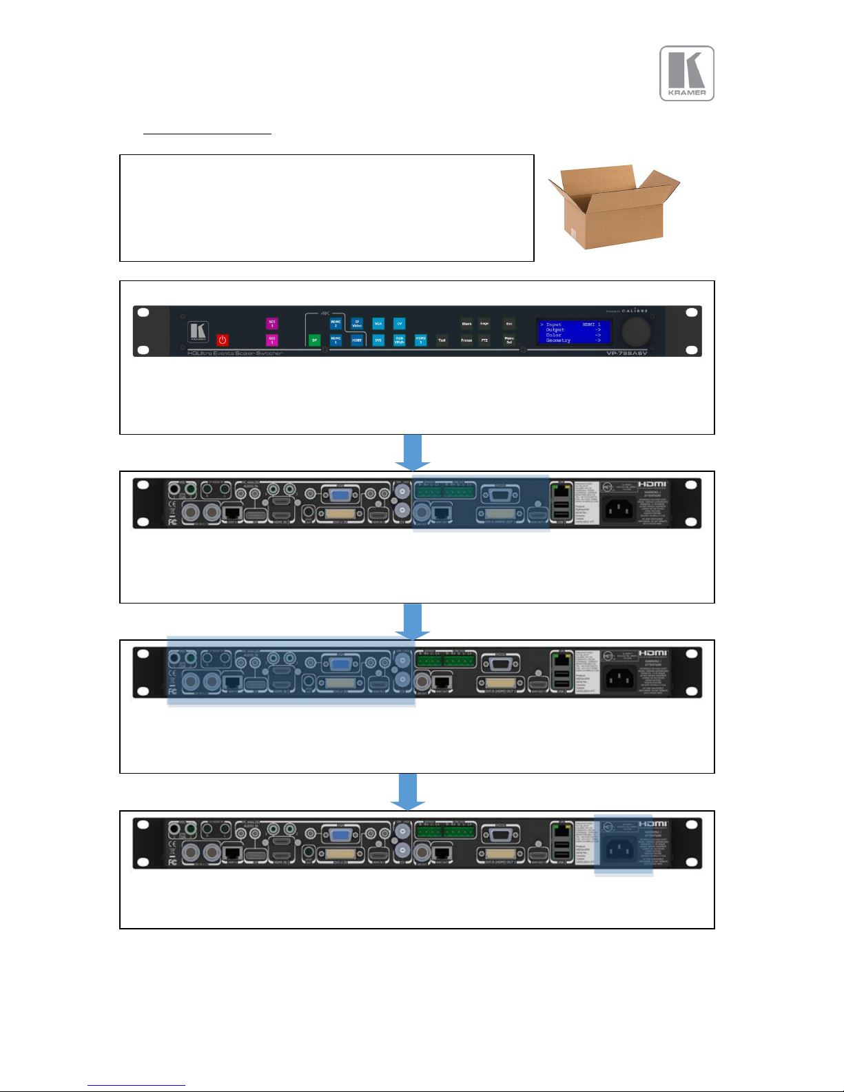
2. Basic Switcher Set-Up
Inspect the shipping box and make sure that no damage was caused
during transportation. If you see any damage, immediately contact
the shipping carrier. Remove the unit, power cord, CD and QSG
from the shipping carton. Inspect the unit and ensure that there is
no damage caused during shipping.
You can install the unit on a clean flat surface or on an equipment rack using the rack-mount ears.
The unit should always be installed in a well ventilated, static free environment and close to the AC
power source. Max. operating temperature is 00C to 400C and 5% to 95% non-condensing
humidity.
Connect the display device (Monitor, Projector, etc.) to one of the output connectors DVI/HDMI
are available on all models, and SDI or HDBaseT are featured only on certain models. If applicable,
connect the speakers or external audio amp to the audio output connectors.
Connect the Input sources (Blu-Ray Player, Set Top Box, PC, etc.). Use connectors from different
groups to achieve the ¼ sec ultra-fast switching. Groups are identified by the button color on the
front panel. If applicable, also connect any audio sources to the 3.5mm stereo jacks.
Inset the power cord to turn-on the unit. The boot-up process takes about one minute.
Page 11
© KRAMER ELECTRONICS LTD.
Issue 1-16 May 30, 2017
11
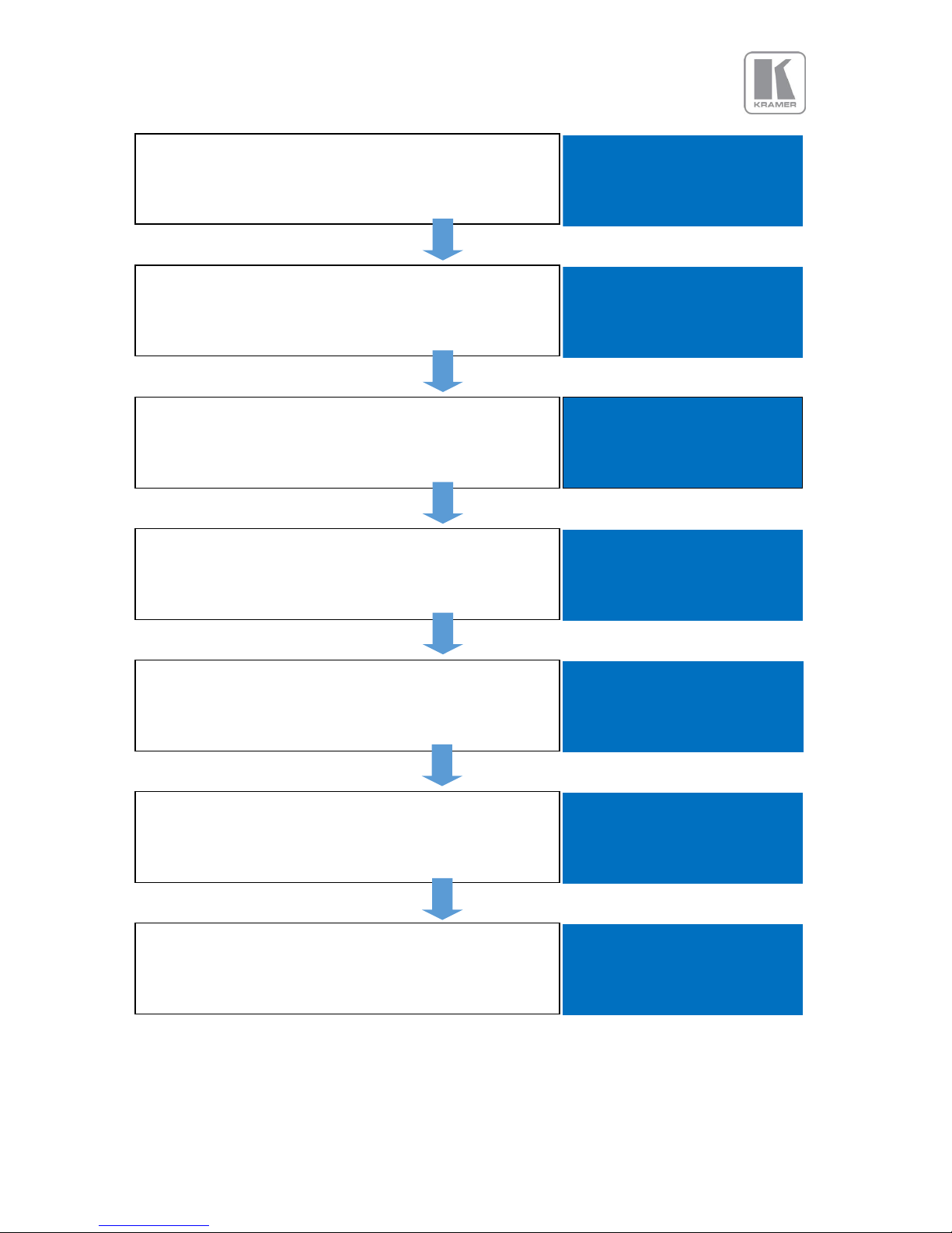
After the unit boots up, the main status menu is displayed.
The menu shows the detected resolution of the input source,
the output resolution and the lock status. In the example, a
4K source was detected on the HDMI-1 input
In: 3840x2160 60Hz
HDMI 1
Out:1920x1080p 59.94
Free Run
Press the Test button to enable a Test Pattern on the output.
Use the rotary knob to select the Warp Adjust pattern. This
pattern provides a border around the whole raster
In: Warp Adjust
TESTPAT
Out:1920x1080p 59.94
Run
Press the select button or the rotary knob to enter the main
menu. Scroll to the Output menu entry and enter the menu
to setup all the output related parameters
Input HDMI 1
►Output
Color
Geometry
Enter the Display Type sub menu by pressing the menu
button.
►Display Type
Gamma/Color/Crush
Output Config
Video Wall
First, select the output resolution from the O/P Mode sub-
menu
►O/P Mode 1920x1080p
Frame Rate 59.94 HZ
I/O Lock Off
Frame Rates
Locate and select the desired output resolution to match the
native resolution of the connected device. In the example,
2560x1600p is selected. Press the Esc key to return to the
previous menu.
O/P Mode
2560x1440p
►2560x1600p
3840x2160p
Repeat the previous steps to change the Frame Rate or the
Genlock source. In the example, a 30Hz frame rate was
selected. Except for LED applications, verify that the Test
pattern with the border outline is shown on the display
►O/P Mode 2560x1600p
Frame Rate 30 HZ
I/O Lock Off
Frame Rates
Page 12

© KRAMER ELECTRONICS LTD.
Issue 1-16 May 30, 2017
12
If the input source is a Mac computer and the unit is
connected to a non-HDCP display, you need to turn off HDCP
to receive non protected content.”
Display Type
Gamma/Color/Crush
►Output Config
Video Wall
Enter the HDCP menu from the Output Config menu and
select HDCP. Enter the menu to turn off HDCP. Immediately
HDCP will also be disabled on all the input channels.
Display HDMI
►HDCP Off
DVI ColorSpace RGB
DVI Range Full
By default, the output is filled with the input image ignoring
any mismatch between the input and output aspect ratios.
To maintain the input source aspect ratio, select the Original
or Crop settings from the Geometry\Pict. Format menu.
Pict. Format
►Original
Full Screen
Crop
Hit Esc several times and return to the status menu. In the
example, the menu indicates that a 4K source is connected to
HMDI-1, the output is set to 2560@30 and the unit is free
running. (no genlock or I/O lock)
In: 3840x2160 60Hz
HDMI 1
Out:2560x1600p 30.00
Free Run
Page 13
© KRAMER ELECTRONICS LTD.
Issue 1-16 May 30, 2017
13
3. System Description
3.1 Front Panel Layout
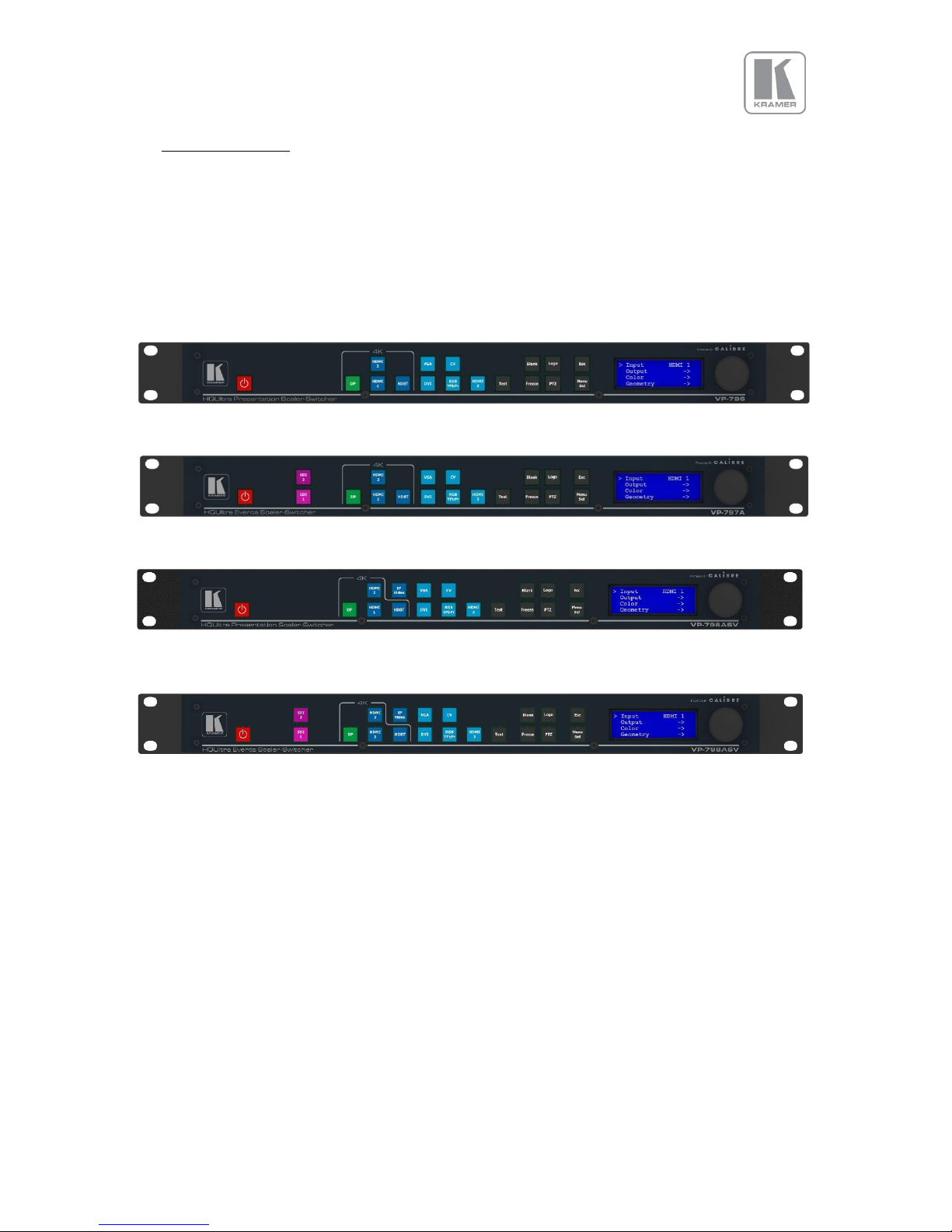
The front panel includes several buttons allowing the user to select between the different inputs and
to perform other functions, a jog wheel and an LCD screen. From the front panel you can navigate the
menus, select the an input and direct access to key functions. The front panel layout is similar
between the different models except for the SDI, HDBT selection keys. Only models featuring these
inputs included these buttons.
VP-796, VP-796A
1 < ------------- 2 -------------- > 3 <- 4-> 5 6 7
VP-797A
1 < ------------- 2 -------------- > 3 <-- 4--> 5 6 7
VP-796ASV
1 < -------- 2 --------- > 3 <- 4-> 5 6 7
VP-797ASV, VP-798ASV
1 < -------- 2 --------- > 3 <- 4-> 5 6 7
1 – Standby key: By pressing the Standby key, the unit is put into standby mode. This is indicated by a
“STANDBY” message on the LCD with the back light turned off. When the unit starts up, the red
Standby key flashes. Once the unit is operational, the Standby key is solid red.
2 – Input channel selection keys: All input channels can be directly selected. The active channel key is
illuminated.
3 – Test Pattern key: Directly activates a Test Pattern. Use the jog wheel to scroll through the
available test patterns.
4 – Direct function keys: Four functions can be directly accessed by pressing their assigned key:
Freeze (stop/resume live video), PTZ (activate/deactivate Pan Tilt Zoom), Logo (show/skip a
predefined logo), Blank (blank the output screen/resume live video).
Page 14
© KRAMER ELECTRONICS LTD.
Issue 1-16 May 30, 2017
14
5 – Menu navigational keys: When the Menu/Sel key acts as an Enter or Select key for menu changes.
A jog wheel is used for menu navigation and changing values. To exit the menu or any submenu press
the Esc key or navigate to the Exit item and press the Menu/Sel key or press the jog wheel.
6 – Front Panel LCD: Displays the Menus on a 4-line display
7 – Jog wheel: The wheel is used for navigating through the menu system and making value changes.
The jog wheel has a push function the creates the same effect as pushing the Menu/Sel key.
Front Panel Shortcuts:
Keypad unlock: Esc + Menu/Sel
Factory reset: Esc + YPbPr (in live operation or at power up)
Set output mode to 720p: Esc + VGA
Firmware version: Standby + Esc ( press the menu button to exit )
Page 15
© KRAMER ELECTRONICS LTD.
Issue 1-16 May 30, 2017
15
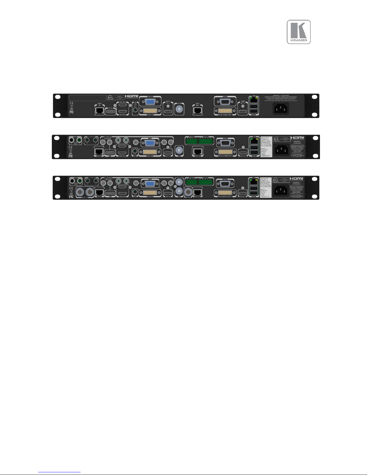
3.2 Rear Panel Layout
The rear panel features all input and output connectors, communication ports and the power supply
connector.
VP-796
VP-796A, VP-796ASV
VP-797A, VP-797ASV, VP-798ASV
1 2 3 4 5 6/ 7 8 9/10 11 12 13/ 14 15 16 17
1 - 2x SD/HD-SDI/3G-SDI input
2 - HDBaseT (UHD/4k) input
3 - Display Port (UHD/4k) input
4 - 2x HDMI-1 & 2 (UHD/4k) input
5 - S/PDIF output
6 - VGA Input
7 - DVI-U (DVI-D and YPbPr through a cable adapter)
8 - 1x HDMI-3 (HD) input
9 - Composite Video (BNC)
10 - Genlock input (BNC)
11 - 3G-SDI output
12 - HDBT (UHD/4k) output
13 - RS232 port
14 - DVI/HDMI1 (HD) output and
15 - HDMI2 (UHD/4k) output
16 - TCP/IP and 2x USB
17 - Power supply connector
Page 16
© KRAMER ELECTRONICS LTD.
Issue 1-16 May 30, 2017
16
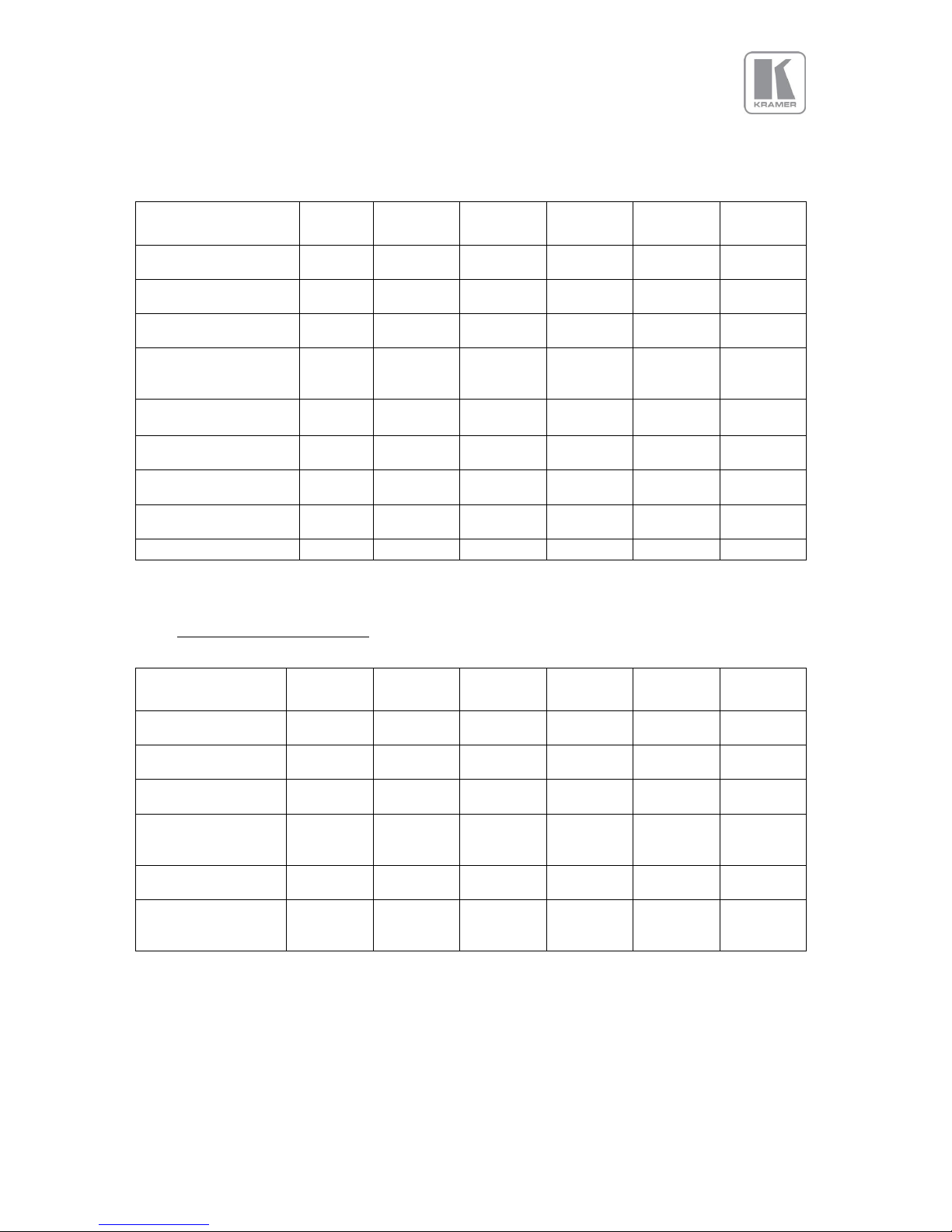
3.3 Input Connector Overview
Model
VP796
VP-
796A
VP-
796ASV
VP-
797A
VP-
797ASV
VP-
798ASV
Display Port (UHD,4K)
via DP connector
2x HDMI (UHD,4K)
via HDMI connector
HDBaseT(UHD,4K)
via RJ45 connector
DVI & analogue
(RGB/RGB/YPbPr)
via DVI-U
VGA analogue via
15HDD
Composite Video
via BNC
3G-SDI
via BNC
Dedicated Genlock
via BNC
Audio Inputs
3.4 Output Connector Overview
Model
VP796
VP-
796A
VP-
796ASV
VP-
797A
VP-
797ASV
VP-
798ASV
1x HDMI (UHD,4K)
via HDMI connector
HDBaseT via RJ45
connector
DVI-D/HDMI via
DVI-U
DVI & analogue
(RGB/RGB/YPbPr)
via DVI-U
3G-SDI I/O
Via BNC
Speaker & Line Out
2x 4-pin terminal
connector
Page 17

© KRAMER ELECTRONICS LTD.
Issue 1-16 May 30, 2017
17
4. Product Specification
This section provides technical specification for all models. The following topics are discussed:
• Power Supply Requirements
• Input Specifications
• Output Specifications
• Supported Formats
• Communication Specifications
4.1 Power Supply Requirement
100V-264VAC 50/60Hz connected via a standard IEC connector located on the rear panel.
4.2 Input Specifications
4.2.1 Composite Inputs
• Composite via BNC connector
• Signal formats Composite (CVBS)
• Standards NTSC, PAL, SECAM
• Composite (CVBS) input level 1V p-p nominal incl. sync
• Input Impedance 75 Ohms
4.2.2 Component Video Inputs
• Via DVI-U connector and appropriate adapter cable
• YPbPr (YUV), YPbPrS and RGsB component video, menu selectable.
• Signal formats 484i (480i) and 576i (SD), 480p, 576p (ED), 720p, 1080i at 50, 59.94 and 60Hz
and 1080p at 23.98, 24, 25, 29.97 and 30Hz.
• Please note this input does not support Computer SVGA signals which should be connected via
the Computer SVGA input, The SVGA input supports the separate H & V syncs.
4.2.3 3G-SDI Input
• Format: SD-SDI, HD-SDI and 3G-SDI YCbCr 4:2:2 serial digital component video.
• Level B support.
When input is 3G Level B (2 stream mapping), there is an option to select which of the two video
streams (Stream 1 or 2) to use. Otherwise it works with whatever mapping is specified in the
SMPTE 352 packet (or defaults to 10bit 4:2:2 if none).
• Input impedance: 75 ohms.
• SMPTE 292M, SMPTE 259M-C and SMPTE 424M compliant, accepts 484i, 576i, 720, 1080i and
1080p single link formats at 270Mb, 1.485Gb or 2.97Gb rates.
4.2.4 Computer (SVGA) Inputs VESA formats
• Signal formats: DOS, VGA – WUXGA up to 165MHz pixel clock
• RGB video level: 0.7V - 1.0V
• RGB input impedance: 75 Ohms
• Sync format : Separate H & V sync at TTL/5V levels.
Page 18

© KRAMER ELECTRONICS LTD.
Issue 1-16 May 30, 2017
18
4.2.5 HDMI-3 & DVI Inputs
• HDMI with or without HDCP, 36-bit video compatible.
• DVI-D input with or without HDCP
• Signal formats - video
o SD: 625i (576i) and 525i (480i) in double-rate formats;
o ED: 480p, 576p;
o HD: 1280x720p, 1920x1080i, 1920x1080psf; 1920x1080p 23.97, 24, 25, 29.94, 30, 50,
59.94 & 60Hz; 2048x1080p 23.97, 24, 25, 29.94, 30, 50, 59.94 & 60Hz.
• Signal formats – computer
o Common VESA graphics formats from VGA to 4k up to 297 MHz (HDMI 1 and HDMI 2)
and 225 MHz (HDMI 3) pixel clock
4.2.6 HDMI-1 & HDMI-2 Inputs
• In addition to all signal formats supported by HDMI-3, these inputs also support 4K signals:
3840x2160p & 4096x2160p 23.97, 24, 25, 29.94, 30, 50, 59.94 & 60Hz (50, 59.94 & 60Hz
supported in YUV 4:2:0 colour space format),
4.2.7 DP Input
• Display Port without HDCP, 36-bit video compatible.
• Signal formats as HDMI 1 and HDMI 2.
4.2.8 HDBT Input
• Uncompressed HD video over RJ45 connector and max.100m CAT5e cable (or better)
• CAT5e/CAT6 for 100m and signals with less than 225MHz Pixel Clock
• CAT6a/CAT7 for 100m and signals up to 297MHz Pixel Clock
• Signal formats as HDMI 1 and HDMI 2.
Graphics formats with odd numbered horizontal active pixels, e.g. 1365x768 are not supported.
Page 19

© KRAMER ELECTRONICS LTD.
Issue 1-16 May 30, 2017
19
4.3 Output Specifications
All output channels are active simultaneously, provided that the input signal is not HDCP encrypted. All
units include an HDMI, and a DVI-U connectors for DVI/HDMI connectivity. Some models feature a BNC
connector for 3G-SDI signals and an RJ-45 connector supporting HDBaseT capability. The DVI-D
connector supports HDMI with 36-bit video and audio formats when connected to a suitable HDMI
receiver. The colour depth of the HDMI signal is determined by a menu selection and the capabilities of
the monitor.
Interlaced outputs are only supported on models with 3G-SDI output.
4.3.1 3G-SDI Output
• Format: SD-SDI, HD-SDI and 3G-SDI YCbCr 4:2:2 serial digital component video
• Input impedance: 75 ohms.
• SMPTE 292M, SMPTE 259M-C and SMPTE 424M compliant, accepts 484i, 576i, 720, 1080i and
1080p single link formats at 270Mb, 1.485Gb or 2.97Gb rates.
4.3.2 HDMI & DVI Outputs
• HDMI with or without HDCP, 36-bit video compatible.
• DVI-D input with or without HDCP
• Signal formats - video
o SD: 625i (576i) and 525i (480i) in double-rate formats;
o ED: 480p, 576p;
o HD: 1280x720p, 1920x1080i, 1920x1080psf; 1920x1080p 23.97, 24, 25, 29.94, 30, 50,
59.94 & 60Hz; 2048x1080p 23.97, 24, 25, 29.94, 30, 50, 59.94 & 60Hz.
• Signal formats – computer
o Common VESA graphics formats from VGA up-to 1080p and 1600x1200
• HDMI output also supports: 4K signals: 3840x2160p & 4096x2160p 23.97, 24, 25, 29.94, 30, 50,
59.94 & 60Hz (50, 59.94 & 60Hz supported in YUV 4:2:0 colour space format)
4.3.3 HDBT Output
• Uncompressed HD video over RJ45 connector and max.100m CAT5e cable (or better)
• CAT5e/CAT6 for 100m and signals with less than 225MHz Pixel Clock
• CAT6a/CAT7 for 100m and signals up to 297MHz Pixel Clock
• Signal formats as HDMI 1 and HDMI 2.
4.3.4 HDCP Output encryption
When the input signal is HDCP encrypted, the DVI-D, HDMI and HDBaseT outputs will also be
encrypted and the 3G-SDI output will be disabled. If the display device does not support
HDCP, the output will be black and a message indicating that the presence of an HDCP signal
will be shown on the screen.
Page 20
© KRAMER ELECTRONICS LTD.
Issue 1-16 May 30, 2017
20
4.3.5 Audio Output
Audio embedded in HDMI and SDI video streams is passed through the system and re-embedded into
the HDMI and SDI output signals.
Also, the unit features a S/PDIF coaxial digital audio output connector for monitoring audio of the HDMI
and SDI channel.
When HDMI is selected as the input channel, the HDMI EDID is read by a video source such as a Blu- Ray
Player. The unit allows the source to provide the formats shown under output formats for HDMI in the
below table. All formats are re-embedded into the HDMI output data stream, those which are not
allowed on the SDI or SPDIF output are muted on the individual channels.
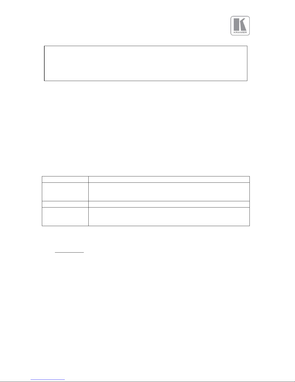
Table 2: Embedded HDMI & SDI Output Audio Formats
Output Channel
Output Format
HDMI
PCM up to 8ch, up to 24Bit, up to 192kHz sampling rate
(incl. 32kHz,44.1kHz,48kHz,96kHz,192kHz)
SDI
PCM up to 8ch, up to 24Bit, 48kHz sampling rate
SPDIF
PCM up to 2ch, up to 24Bit, up to 96kHz sampling rate
(incl. 32kHz,44.1kHz,48kHz,96kHz)
The unit will not pass through any Dolby Digital, MPEG2 or DTS audio formats
4.4 Analog Audio
Units supporting audio include up-to 8 analog stereo Inputs, two microphone Inputs with phantom
power and an audio mixer.
Analog stereo signals are connected to the unit via 3.5 mm jack sockets, except for the CV input that is
associated with two RCA connectors. Using the audio menu, any video input can be link with any
audio input and mixed with the mic inputs.
Audio models also include stereo audio power amplifier supporting 15W RMS loudspeaker per output
and separate stereo balanced line level audio outputs for external amplifier systems. The analog
stereo outputs are available on two phoenix connectors.
The user can turn off the unit’s HDCP compliance to allow non-encrypted content to pass
through the unit. This is an important feature specially when using a MAC computer as the
source. The MAC will encrypt its output signal if a compliant device is seen attached to its
output regardless of the copy protection requirements of the content. By turning off HDCP,
the MAC will see a non-compliant device and therefore will not encrypt its output. When
HDCP compliance is turned off, encrypted sources will not be displayed.
Page 21
© KRAMER ELECTRONICS LTD.
Issue 1-16 May 30, 2017
21
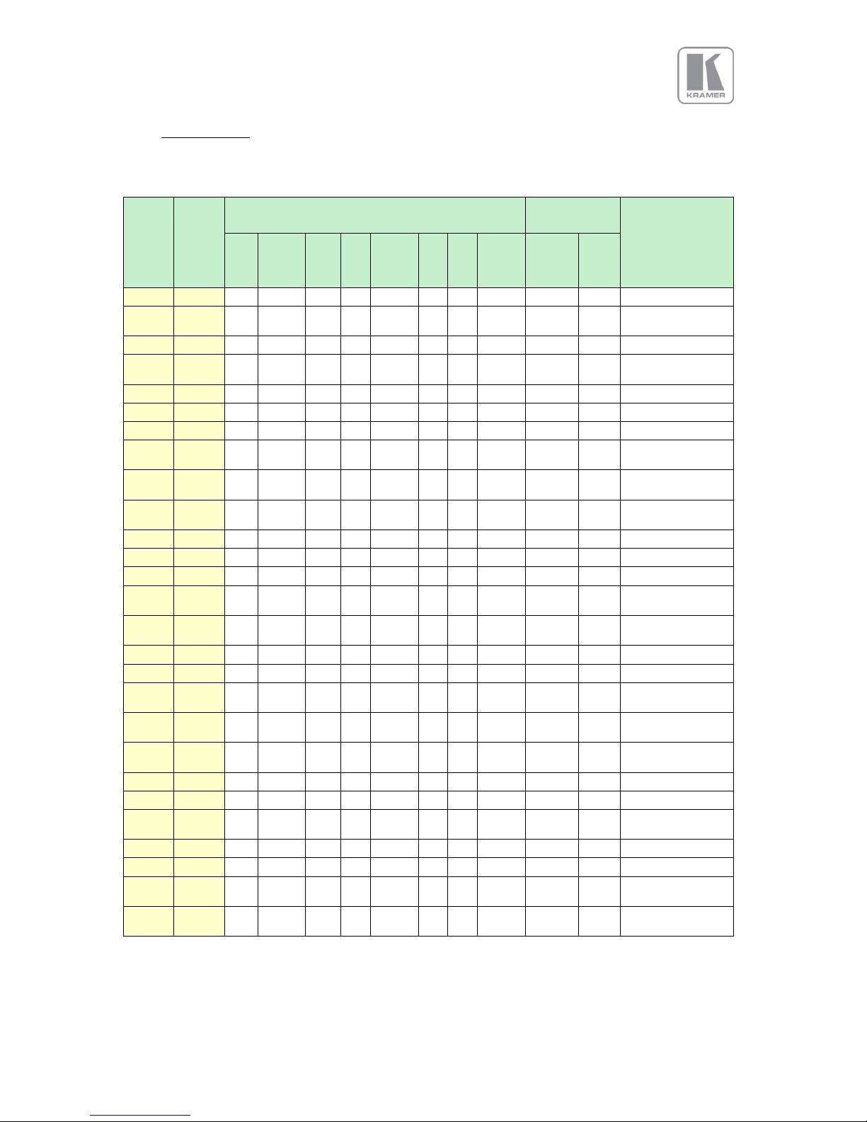
4.5 Video Formats
Table 3: Supported Video Formats
Horiz.
Active
Pixels
Vert.
Active
Lines
Vertical Refresh Rate (Hz)
Outputs
Specification
60
59.94
50
30
29.97
25
24
23.98
DVI
HDMI
HDBT
3GSDI
640
480
VESA DMT
720
480i
EIA/CEA-861-B
Format 6 (NTSC)
720
480p
720
576i
EIA/CEA-861-B
Format 17 (PAL)
720
576p
800
600
VESA DMT
1024
768
VESA DMT
1280
720
EIA/CEA-861-B
Format 4
1280
768
VESA CVT
001M9/VESA DMT
1280
800
VESA CVT
001MA/VESA DMT
1280
1024
VESA DMT
1360
768
VESA AddDMT
1366
768
proprietary
1440
900
CVT 1.30MA/VESA
DMT
1400
1050
VESA CVT
001M3/VESA DMT
1600
1200
VESA DMT
1680
1050
VESA CVT 002MA
1920
1080i
EIA/CEA-861-B
Format 5
1920
1080p
EIA/CEA-861-B
Format 5
1920
1200
VESA CVT 002MA-
R/VESA DMT
2048
1080
proprietary
2048
1200
proprietary
2560
1080
EIA/CEA-861-F
VIC=86
2560
1440
VESA CVT 004M-R
2560
1600
VESA CVT 004M-R
3840
2160
EIA/CEA-861-F
VIC=93
4096
2160
EIA/CEA-861-F
VIC=98
Page 22

© KRAMER ELECTRONICS LTD.
Issue 1-16 May 30, 2017
22
4.6 Communications Specification
The unit supports both TCP/IP and RS-232 serial protocols.
Either port can be used to send API commands to the unit. Software updates can also be performed
from the Ethernet port.
Restoring the unit to the factory default state, doesn’t affect communication settings.
4.6.1 TCP/IP Port
The unit supports DHCP and static modes. If DHCP is active, the unit will be assigned an IP address by
the network’s DHCP master. If the unit is set in the static mode, the user needs to set the IP address
manually. Restoring the unit to the factory default state, doesn’t affect communication settings.
Port 30000 is used.
4.6.2 Serial Connector pinout and RS-232 Configuration Settings
Table 4: Serial Connector Pinout
DB-9
Pin
Signal
name
Function
2
RXD
RS232 levels, Receive (from the HOST)
3
TXD
RS232 levels, Transmit (to the HOST)
5
DGND
Ground
The serial communication configured as follows:
Table 5: RS-232 communication settings
Parameter
Value
Baud rate
115200 Bits/second
Stop Bits
1
Number of bits received/transmitted in the BYTE
8
Parity Bits
No Parity
Flow Control
Off
Page 23

© KRAMER ELECTRONICS LTD.
Issue 1-16 May 30, 2017
23
5. Unit Control
The unit can be controlled via the front panel, a web page built-in into the unit or an API protocol
interface. The next two chapters describe the Front Panel and Web Browser control methods. The API
interface can be found in a separate document available on our web site.
6. Front Panel Control
You can enter the main menu by pressing the Menu/Sel key from the status screen. You can use the
jog wheel and Menu/Sel and Esc buttons to navigate through the different menus.
A complete diagram of the menu tree is shown in Appendix A. The audio menu tree for units fitted
with the audio option is shown in Appendix B.
Next, is a brief description of the functions and settings available from the front panel menus.
Main Menu
Under the main menu are the main sub-menus that allow user to setup and operate the unit. These
sub-menus are:
• Input
• Output
• LED Screen Size
• PIP
• System
• Audio
• Status
Each menu includes an Exit entry to return to the previous level. Some adjustments are not applicable
to all signal types or operating modes, in which case those non-applicable functions will be greyed out
and are not accessible.
The unit is designed to have separate memories for all the settings in each section. All Input parameters
are specific to your chosen input channel and input signal type, and are not global to the unit. For
example, if you change the settings for the composite video channel, you will not affect the settings you
may have made in the DVI channel.
Page 24

© KRAMER ELECTRONICS LTD.
Issue 1-16 May 30, 2017
24
6.1 Input
This menu contains adjustments related with the outputs of the unit.
6.1.1 Input Selection
This menu provides an additional method of selecting the desired input.
Depending on the specific model, some of these input selections may not be available.
Test patterns can be selected even when there are no inputs connected to the unit. Different test
patterns can be selected by scrolling the jog wheel.
Settings:
• SDI-1*
• SDI-2*
• Display Port
• HDMI-1
• HDMI-2
• HDBaseT*
• DVI
• HDMI-3
• VGA
• YPbPr/RGB
• Composite Video
• Test Pattern
Default : HDMI-1
* : These inputs are not present on all the models. Please refer to the Input Connector Overview to
determine the appropriate models.
Page 25

© KRAMER ELECTRONICS LTD.
Issue 1-16 May 30, 2017
25
6.1.2 Input Config
6.1.2.1 Analog Inputs
6.1.2.1.1 VGA Setup
• Clock\Phase
Frequency (Clock) and phase can also be altered manually, as the vertical and horizontal position
Settings: 0 to 32
Default : 0
• Colour Space
Settings: RGB or YCbCr
Default : RGB
• Range
The greyscale range can be reduced by switching from full to limited (see range values discussed
in the output config section)
Settings: Full / Limited
Default : Full
• Reset Mode
A reset button to factory defaults is provided, to return the phase, clock and positional settings to
the original positions.
• EDID IN
The preferred video mode can be selected in the EDID Input Format menu. This setting can force
the source to output a certain video mode provided the driver of the graphic card reads the
preferred timing in the EDID. Most likely the PC needs to be rebooted for the driver to notice the
EDID change.
• EDID F/R :
The preferred video frame rate can be selected from the provided menu. This setting can force
the source to output the selected frame rate provided the driver of the graphic card takes notice
of the preferred timing in the EDID. The PC most likely has to be rebooted for the driver to take
notice.
Default : 1920x1080p
6.1.2.1.2 RGB/YPbPr Setup:
Same as VGA Setup, except there is no concept of EDID with component video and thus no EDID
Input Format menu.
6.1.2.1.3 CVBS Setup:
• CCS is a filter to reduce luminance to chrominance cross talk of composite video signals (only)
which appears as a coarse rainbow pattern or random colours in regions of fine details.
Default : On
Page 26

© KRAMER ELECTRONICS LTD.
Issue 1-16 May 30, 2017
26
6.1.2.2 Digital Inputs
6.1.2.2.1 DP, HDMI 1, HDMI 2, HDMI 2, DVI Config.:
▪ Colour space
The automatic Colour Space and Range settings can be overwritten in this menu.
Settings: RGB or YCbCr, if Auto setting does not give the desired result
Default: Auto
• Range
Settings: Limited. Full or Auto range.
Default: Auto
• Deep Color:
The EDID can be configured to enable deep colour capability. The unit can process colour depth of
24/30/36 per channel (DP input can only accept 24/30 bits). Deep Colour can be off, if the source
outputs 24bits, or set to on when the source outputs 30 or 36bits. The detected source output
colour depth is reported on the corresponding menu.
Settings: On/Off
Default: Off
• EDID In
The preferred video resolution can be selected from the provided menu. This setting can force the
source to output the selected format provided the driver of the graphic card takes notice of the
preferred timing in the EDID. The PC may have to be rebooted for the driver to take notice.
Default: 1920x1080p
• EDID F/R :
The preferred video frame rate can be selected from the provided menu. This setting can force
the source to output the selected frame rate provided the driver of the graphic card takes notice
of the preferred timing in the EDID. The PC most likely has to be rebooted for the driver to take
notice.
• HDCP
When setting HDCP Input to off, the unit pretends to be non HDCP compliant allowing the source
to not encrypt data. Please note that the source will not encrypt the input data only if the source
content is not copy protected. If for example, the source is a Blu-ray player and HDCP is turned off,
then the player will not send any data to the unit. When HDCP is set to off, the output is unencrypted
and this menu item is greyed out. This selection is not available for the Display port input
Settings: On/Off
Default: On
6.1.2.2.2 HDMI Audio Support
The audio capabilities of the HDMI port can be configured by means of overwriting the EDID. The
unit described in this manual is part of an audio/video processing chain and devices behind the
unit may not be able to cope with advanced audio. The unit can signal the source to match with
the audio capabilities of the display (setting Match Display 1/2), or to be S/PDIF friendly or to be
Page 27

© KRAMER ELECTRONICS LTD.
Issue 1-16 May 30, 2017
27
SDI friendly (48kHz PCM only, 2ch or 8ch). If the unit is set to Full the capabilities of the unit are
communicated by means of the EDID to an audio source.
Settings: On/Off
Default: On
6.1.2.2.3 SDI Setup
6.1.2.2.4 SDI to HDMI Audio
SDI audio input is routed to the HDMI and 3GSDI output connector. Two consecutive SDI
audio channels can be output on the HDMI/3GSDI output interface. The group can be chosen,
or all eight SDI audio channels can be transmitted
Settings: Stereo Ch. (1,2)/(3,4)/(5,6)/(7,8)/Multichannel
Default: Stereo Ch. (1,2)
6.1.2.2.5 Level B Priority
Since only one Level B signal can be processed by the unit, in this entry the user needs to
prioritized the SDI input with the Level B signal.
Settings: SDI1 / SDI2
Default: SDI1
6.1.2.2.6 SDI1/SDI2 Level B Stream
Selects which of the two video streams (Stream 1 or 2) to use.
Settings: SDI1(2) Level B Stream: Stream 1(2)
Default: SDI1 Level B Stream: Stream 1
SDI2 Level B Stream: Stream 2
6.1.2.3 Test Pattern Setup
6.1.2.3.1 Test Pattern Selection
▪ When the Test button is pressed on the front panel, different patterns can be selected by
turning the jog wheel. For unit control through a web browser or to set up a certain
default test pattern please use the input configuration menu.
▪ Custom test patterns loaded into the unit through the web interface, and selected as the
other test patterns.
▪ Depending on the Output resolutions, test pattern images are resized dynamically by the
software resolution to completely fit the output raster space.
▪ Available Test Patterns:
o Red Curtain
o Green Curtain
o Blue Curtain
o Grey V Bars
o Grey H Bars
Page 28

© KRAMER ELECTRONICS LTD.
Issue 1-16 May 30, 2017
28
o Aspect Test
o Multi Test
o Warp Adjust
o SMPTE
o PLUGE
o Moving Cross
o Custom 1
o Custom 2
o Custom 3
o Custom 4
Default: Pattern: SMPTE
6.1.2.3.2 Test Pattern Tone
A test tone can be set to accompany the test pattern
Settings: On / Off
Default: Off
6.1.2.3.3 Color (FG) of the Moving Cross
Settings: 0 to 7
0 = black
1 = white
2 = yellow
3 = cyan
4 = green
5 = magenta
6 = red
7 = blue
Default: 1 (White)
6.1.2.3.4 Moving Cross Background (BG) color
Settings: 0 to 8
0 = black;
1 = white;
2 = yellow;
3 = cyan;
4 = green;
5 = magenta;
6 = red;
7 = blue;
8 = Multicolor, sets the four quadrant colours as red, green, blue and black)
Default: 8: (Multicolor)
6.1.2.3.5 Moving Cross Speed
Number of pixels that the test pattern moves per frame
Settings: 1 to 10
Default: 1
Page 29

© KRAMER ELECTRONICS LTD.
Issue 1-16 May 30, 2017
29
6.1.2.3.6 Moving Cross Width
The width of the moving cross in pixels
Settings: 4 to 40
Default: 40
6.1.2.4 Input Enable
Each input can be disabled locking the associated front panel button.
Settings: 0 or 1 0: Disable / 1: Enable
Default: All Enabled
6.1.2.5 Switching Transition
The switching transition can be selected to be Freeze, Blank, Fast Fade and Slow Fade.
• Freeze : Halts the prior channel image until the new channel image is stable. Freeze is the default
mode.
• Blank : Switches the output to a black screen instead of the last shown image.
• Fast and Slow Fade : Fades between the channels with different transition times
Settings: Freeze, Blank, Fast Fade and Slow Fade
Default: Freeze
6.1.2.6 Streaming Video
Units fitted with the streaming option can accept 1080p H.264 Streaming Video via the Gigabit Ethernet
Port and route it to the output. API commands send to the unit via the Ethernet port can be processed
simultaneously with the streaming video. The unit interfaces to the video server via the RSTP network
control protocol.
The user needs to enter the IP address and port of the stream source and the file name. Additionally
four more selections are provided for a simple operation: Start, Stop, Auto Start and Auto reconnect.
Settings: Source IP address & Port, File name, Start, Stop, Auto Start, Auto reconnect
Default: Auto Start=On, Auto reconnect=Off
Page 30

© KRAMER ELECTRONICS LTD.
Issue 1-16 May 30, 2017
30
6.1.2.7 Custom Modes
From this menu the user can create up-to four custom progressive or interlaced resolutions to
interface with sources providing non-standard video format. These custom resolutions can also be
selected in the EDID selection for each input. Custom resolutions are not available for the SDI inputs.
This menu is available on selected models.
Settings: CMx Width: from 640 to 4096; CMx Height: from 480 to 2160; CMx Scan Type:
Progressive/Interlaced
Default : CMx Width: 1920; CMx Height: 1080; CMx Scan Type: Progressive
6.1.3 Colour Adjustments
6.1.3.1 Black-Level Offset
Used to select 7.5 IRE black level set-up adjustment. Should always be set to 7.5 IRE for HDMI video
and NTSC video inputs and should usually be off for PAL analog video inputs.
Settings: 0 IRE, 7.5 IRE
Default : 0 IRE
6.1.3.2 Brightness (Black-Level)
Brightness controls the offset applied to the video signal. (same as the brightness control on a TV)
Settings: -50 to 50 in steps of 1
Default : 0
6.1.3.3 Contrast
Contrast controls the gain applied to the video signal.
Settings: -50 to 50 in steps of 1
Default : 0
6.1.3.4 Saturation
Controls the video colour saturation, (applies individually to all video inputs but not computer input
signals or formats).
Settings: -50 to 50 in steps of 1
Default : 0
6.1.3.5 Hue
Adjusts the colour hue of NTSC signals. This is not applicable for computer input signals or formats.
Settings: -50 to 50 in steps of 1
Default : 0
Page 31

© KRAMER ELECTRONICS LTD.
Issue 1-16 May 30, 2017
31
6.1.3.6 RGB Values
This is a user-defined colour temperature setting where R,G,B gain (white balance) and offset/bias
(black balance) can be adjusted separately in order to match the display device.
This control is not available for output modes with colour space format YUV 4:2:0.
Settings : Red/Green/Blue Gain/Bias : -512 to 512
Default : 0
6.1.3.7 Colour Temp
A preset range of Colour Temperature allowing the user to select from pre-configured colour
temperatures to match the colour temperature of the incoming signal. If this value Native Colour
Temp value in the Output menu are the same, no conversion is performed.
Settings: 3200K, 3700K, 5500K, 6500K, 7500K, 9300K
Default : 6500K
6.1.3.8 Input Gamma
Set this value to match the gamma of the input signal. Input and output gamma both default to 1.0. If
they are both set to the same value, there is no effect on the image.
Settings: 1.0 to 3.0 in steps of 0.1
Default : 1.0
6.1.4 Geometry
This menu contains adjustments associated with setting up position, aspect ratio and scale of the
input signal.
6.1.4.1 Picture Format
This feature allows the user to format the output image when the input aspect ratio is different to the
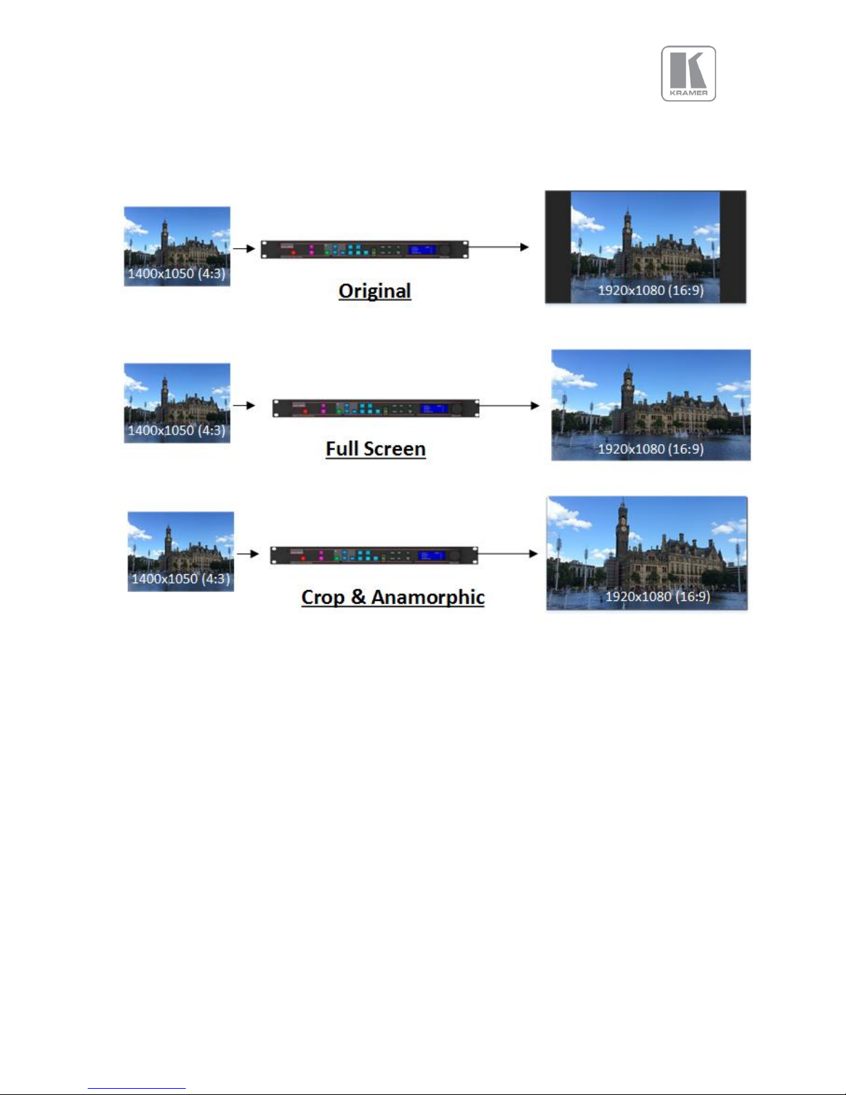
display panel’s aspect ratio. Four formats are available: Original, Full Screen, Crop and Anamorphic.
Original: The input image is scaled to fit the display area either horizontally or vertically without any
distortion. The input aspect ratio is preserved and unused areas on the top/bottom or left/right are set
black.
Full Screen: The input image is scaled to completely fit the display area without preserving the aspect
ratio of the source. This will cause distortion but no black areas will be visible.
Crop: The input image is scaled to completely fit the display area while preserving the aspect ratio of
the source. Portions of the input image on the top/bottom or left/right will be cropped out of the output
image.
Page 32
© KRAMER ELECTRONICS LTD.
Issue 1-16 May 30, 2017
32
Anamorphic: The image will be treated as in crop, but it is always scaled to a 16:9 aspect ratio.
The images below provide examples how an input image 1400x1050(4:3) is scaled to an
1920x1080(16:9) output with the four available formats.
Figure 1: Picture Format Examples
6.1.4.2 Overscan
Overscan is used to slightly zoom into the image. Therefore, the border area of an image is no longer
displayed on the screen. This cuts off unwanted features at the top or bottom from e.g. head switching
in legacy video images.
Settings: 0 to 10 in steps of 1
Default: 0
Page 33

© KRAMER ELECTRONICS LTD.
Issue 1-16 May 30, 2017
33
6.1.4.3 Pan Tilt Zoom (PTZ)
This menu provides settings to zoom and shrink the image, pan horizontally and tilt vertically within the
image. PTZ can be switched on or off and the settings can be saved per input channel or globally, i.e. if
applied globally the same PTZ settings are applied when switching input channels or changing the input
mode. The Zoom setting allows zooming into the image or shrink it.
When Aspect Lock is set to On, vertical zoom is disabled and the horizontal zoom or shrink factor is also
used to vertically adjust the image. In this mode the aspect ratio is preserved.
When Aspect Lock is Off, horizontal and vertical scaling factors are set separately, regardless of the
input image aspect ratio.
Off raster panning is also allowed, i,e, the image can be shifted outside the active area of the display.
The PTZ settings can be set to the default settings with the reset button.
Settings: On/Off
Default: Off
6.1.4.3.1 PTZ Enable
PTZ needs to be turned on before the other functions are enabled.
Settings: On/Off
Default: Off
6.1.4.3.2 PTZ Setting
This setting determines whether the PTZ values are applied on the selected input, or globally
Settings: Per Input / Globally / Per Input per Mode
Default: Per Input
6.1.4.3.3 PTZ Value
This setting determines whether the PTZ adjustments are done in pixel increments or in percentages of
the input image size.
Settings: Pixels / Percent
Default: Pixels
Page 34

© KRAMER ELECTRONICS LTD.
Issue 1-16 May 30, 2017
34
6.1.4.3.4 Pan
This setting determines the amount of horizontal pan. In other words, it defines where the scaler selects
the horizontal start of the image to be processed. Positive values move the output scaled image to the
right and negative values to the left.
Settings: -50% to +50%
Default: 0
6.1.4.3.5 Tilt
This setting determines the amount of tilt (vertical pan). In other words, it defines where the scaler
selects the first line of the image to be processed. Positive values move the output scaled image
downwards and negative values upwards.
Settings: -50% to +50%
Default: 0
6.1.4.3.6 Zoom-H
This setting determines the amount of horizontal zooming in or out of the input image. Positive zoom
will cause only a portion of the input image to fill the output raster.
Settings: -25% to +400%
Default: 0
6.1.4.3.7 Aspect Lock
In order to maintain the aspect ratio of the input source, by default Aspect Lock is set to on to allow the
Zoom-V setting to change simultaneously with Zoom-H.
Settings: On / Off
Default: On
6.1.4.3.8 Zoom-V
The Aspect Lock needs to be off, for this setting to take effect. Zoom-V determines the amount of
vertical zooming in or out of the input image. Positive zoom will cause only a portion of the input image
to fill the output raster.
Settings: -25% to +400%
Default: 0
6.1.4.3.9 PTZ Reset
Resets all PTZ parameters to the default settings
Page 35

© KRAMER ELECTRONICS LTD.
Issue 1-16 May 30, 2017
35
6.1.5 Enhancement
The enhancement menu provides image enhancement functions. Note that the enhancement settings
apply only to video input signal and not to computer graphics signals.
6.1.5.1 Sharpness
Control of the sharpening enhancement filters' levels. These are peaking filters to improve highfrequency response. Note that setting this control too high on a signal which already has good high
frequency response will cause ringing or ghosting.
Settings: -4 to 4 in steps of 1
Default : 0
6.1.5.2 Detail
This filter provides powerful 2D image enhancement which can be used to greatly improve detail
definition and clarity without causing image ringing or ghosting. It improves both horizontal and vertical
detail. Correct setting of the detail enhance filter can make SD signals look virtually indistinguishable
from true HD. At setting 0 the filter is switched off, with setting 3 providing the highest effect.
Settings: 0, 1, 2, 3
Default : 1
Page 36

© KRAMER ELECTRONICS LTD.
Issue 1-16 May 30, 2017
36
6.2 Output
This menu contains adjustments related with the outputs of the unit.
6.2.1 Display Type
6.2.1.1 Output Mode (Resolution)
The selected output resolution should match the native resolution of the imaging device to avoid
double scaling. When you are connected to an LED display, choose a resolution that is equal or
greater than the display resolution. Then use the LED screen size adjustment to accurately scale to
the LED wall. Some low cost LED walls display artefacts when using lower resolution settings. To deal
with these artefacts it is sometimes necessary to choose a much higher resolution, and then use the
LED screen size adjustment as described above.
The 3GSDI output does not feature the PC resolutions; only 480i/p, 576i/p, 720p and 1080i/p output
modes are supported.
Settings: See the Supported format table in the Product Specification chapter of this document
Default : 1920x1080p
6.2.1.2 Frame Rate
As with the output resolution, the output frame rate should match the native frame of the imaging
device. Some frame rates may not be available depending on the selected resolution.
In auto mode the output frame rate follows the input frame rate if it supported by the output resolution.
If the input frame rate is not supported by the output resolution, then the unit determines the output
frame according to a procedure programmed in the software.
Settings: 60 Hz, 59.94 Hz, 50 Hz, 48 Hz, 25Hz, 24 Hz, 23.97, Auto
Default : 59.94Hz
6.2.1.3 I/O Lock
From this menu, the user can select the genlock mode of the unit. If I/O Lock is off, the output free-runs
with a fixed refresh rate determined by the frame rate setting. In this mode, the output vertical refresh
sync deviates slightly from the input vertical refresh sync, even if both are set at the same rate,
occasionally causing frame dropping or repeat.
If I/O Lock is set to On, the output refresh rate follows the input video refresh rate if possible. If not, the
output is operated with a fixed refresh rate determined by the frame rate setting.
If I/O Lock is set to Genlock, the output refresh rate will follow the vertical sync of the signal connected
to the Genlock BNC connector. Genlock is achieved when the Genlock vertical sync rate matches the
vertical sync rate set in the output menu. Valid combinations are 50Hz/50Hz, 59.94Hz/59.94H and
60Hz/60Hz. If genlock is not achieved, the output frame rate refresh rate is determined by the frame
rate setting.
Page 37
© KRAMER ELECTRONICS LTD.
Issue 1-16 May 30, 2017
37
The LCD main status menu indicates the genlock status: (I/O Locked or Genlocked) or in free run mode
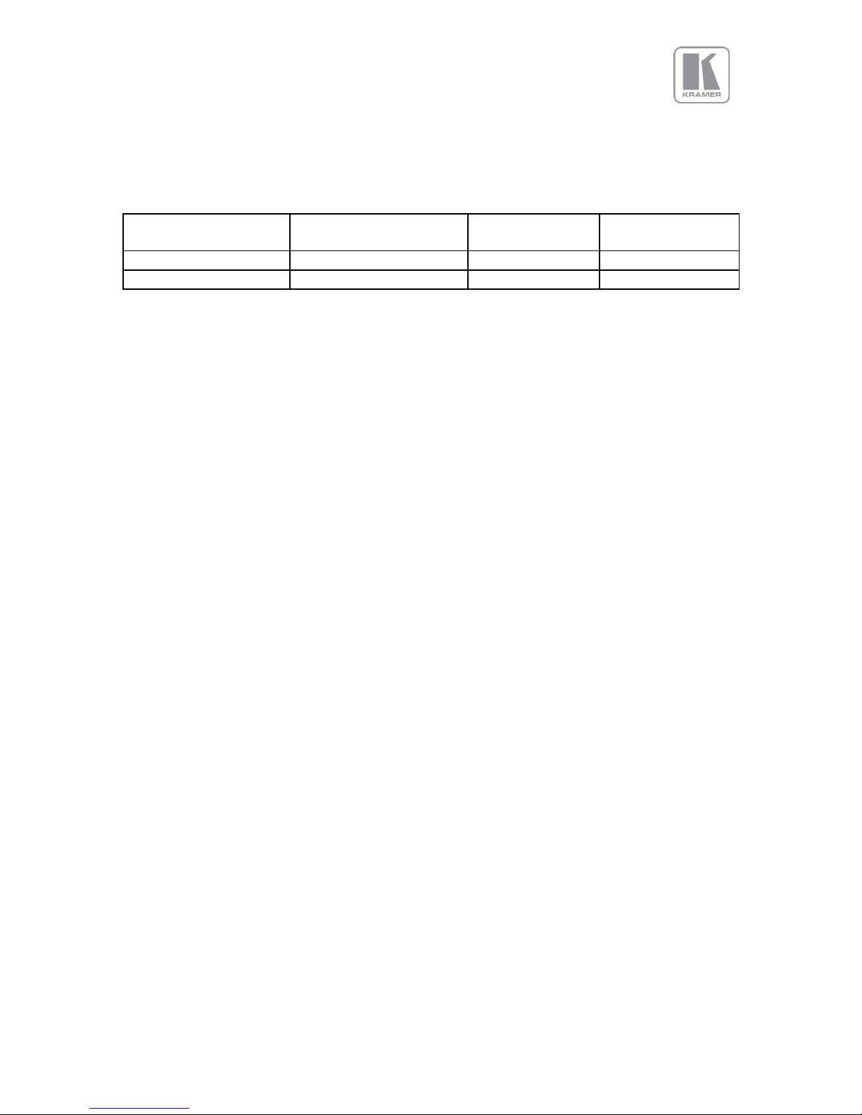
(Free Run). In order to achieve clean switch between input selections, follow the locking settings
described in the table below.
Table 6: I/O Lock behaviour
I/O Lock = On
(Lock to i/p video)
I/O Lock = Genlock
I/O Lock = Off
(Free Run)
Auto Frame Rate
Never Clean
Always Clean
Depends on Inputs
Fixed Frame Rate (any)
Never Clean
Always Clean
Always Clean
If the output Frame rate is set to Auto, all types of genlock signals (e.g. NTSC & PAL, Tri-level sync)
signals can be accepted. On the other hand, if a specific frame is selected, for example 59.94Hz, a
Genlock reference signal of 59.94Hz can only be accepted and the unit will not lock to a 50Hz
reference signal.
If the output Frame rate is set to Auto and I/O lock is off, input switching may-not be clean. Clean
switching will depend how close the frame rates of the current and next input channel are.
Settings: Off, On, Genlock (for models supporting genlock)
Default : Off (Free Run)
6.2.1.4 Frame Rate (Enable)
From this menu the user can choose the output frame rates that the unit can output. By de-selecting
certain frame rates, you can prevent the unit from outputting frame rates that cannot be accepted by
the display.
Settings: 60 Yes/No, 50 Hz Yes/No, 48 Yes/No, 30/29.97Hz Yes/No, 25 Yes/No, 24/23.98 Yes/No
Default : 60Hz Yes, 50Hz Yes, 48Hz No, 30/29.97Hz Yes, 25Yes, 24/23.98Hz Yes
6.2.1.5 Custom Modes (Resolutions)
From this menu the user can create up-to four custom output progressive or interlaced resolutions.
These resolutions are available for selection from the Display Type sub-menu under the Output menu.
These custom resolutions can also be selected for each input from the Input Conf. sub-menu under
the System menu. The custom resolutions are not available for the SDI output. This menu is only
available for the LED driving models.
Settings: CMx Width: from 640 to 4096; CMx Height: from 480 to 2160; CMx Scan Type:
Progressive/Interlaced
Default : CMx Width: 1920; CMx Height: 1080; CMx Scan Type: Progressive
Page 38

© KRAMER ELECTRONICS LTD.
Issue 1-16 May 30, 2017
38
6.2.2 Gamma/Colour/Crush
Native Colour Temp allows the user to select from pre-configured colour temperatures to match the
display. If this value is the same as the Colour Temp value in the (Input) Colour menu, no conversion is
performed.
Settings: 3200K, 3700K, 5500K, 6500K, 7500K, 9300K
Default : 6500K
6.2.2.1 Output Gamma
Output gamma allows to re-gamma video signals with pre-configured gamma values to match the
display. Input gamma and output gamma both default to 1.0. If they are both set to the same value,
there is no effect on the image. If you need to reduce the level of certain color in the image, select a
higher value for the input colour Temp in the Colour menu, or a lower number for the Native Colour
Temp in the Output menu.
Settings: 1.0 to 3.0 in steps of 0.1
Default : 1.0
6.2.2.2 Black Crush (LED models only)
This feature is available for models supporting LED walls. The input black level should be optimized
prior to using Black Crush and any filter settings should also be optimized first. Black Crush is not a
replacement for correct input settings, but it is available to clean up any remaining black level noise
on the signal which may be visible on very bright LED screens without reducing the peak white
brightness. This function is not the same as adjusting the overall black level.
It is recommended to use a setting between 0 and 16 and not more than 20. For most LED screens the
optimum setting for Black Crush is between 8 and 20. For particularly noisy subject material, 24 can be
used but detail loss may occur in dark areas. If too high a setting is chosen, image solarization may be
observed where dark image areas turn completely black or even change colour.
Settings: 0 to 255 in steps of 1
Default : 0
Page 39

© KRAMER ELECTRONICS LTD.
Issue 1-16 May 30, 2017
39
6.2.3 Output Config
6.2.3.1 HDMI & DVI Outputs
Internally, the output interface processes data at a full ten bits per colour. The colour depth on the
HDMI outputs is determined by the supported standard of the attached monitor or device when set to
DVI/HDMI.
DVI 1.0 and HDMI 1.1/1.2 devices are set at 24 bit, for HDMI 1.3 or later compliant devices it is up to 36
bit. The DVI forced selection will output video with 24 bit colour depth irrespective of the supported
standard of the attached monitor.
Settings: DVI forced, DVI/HDMI, HDMI 8-bit, 10-bit, 12-bit
Default : HDMI
6.2.3.2 HDCP
HDCP encryption support on the output can be switched off as is in the input. This means the unit
pretends to be non-HDCP compliant on the DVI/HDMI output port and consequently does not encrypt
data.
At the same time, HDCP is also turned off at the input ports. This allows the unit to accept non-HDCP
encrypted data. If the source however, is HDCP encrypted, then the output will be black.
Settings: On, Off
Default : On
6.2.3.3 DVI Colour Space
This menu allows users to select between the RGB and YPbPr colour spaces
Settings: RGB, YPbPr
Default: RGB
6.2.3.4 DVI Range
When set to Default CEA, the output modes have limited range, and VESA modes have full range.
Therefore, an incoming limited range mode is either passed through when the output is set to a CEA
output mode or expanded when the output is set to a VESA mode. An incoming full range mode is
either compressed when the output is set to a CEA output mode or passed through when the output
is set to a VESA mode.
If the HDMI/DVI output does not operate properly, the range can be changed manually. A limited
video range is only using the following greyscale for video information - 8 Bit System: 0x10 .. 0xEF, 10
Bit System: 0x040 .. 0x03BF, 12 Bit System: 0x100 .. 0xEFF.
Settings : Default, Limited, and Full
Default : Full
Page 40

© KRAMER ELECTRONICS LTD.
Issue 1-16 May 30, 2017
40
6.2.4 Video Wall
The Video Wall menu provides controls to set up multiple units in a multi-screen application.
Multiple screens are stitched together to provide a bigger display with higher resolution than a single
display. Each display is driven by a separate unit.
In a multi projection display the individual projections typically are chosen to overlap to give seamless
transitions. Multiple LED walls or LCD/Plasma screens do not have overlapping regions. The Blend
Width is set to zero. When using Video Wall to drive one single large screen, it is essential that all
units are I/O locked or genlocked, otherwise motion tear will be observed at the boundaries of the
image processed by each unit.
6.2.4.1 Auto Zoom
Switches on the auto zoom resizing the video image to display the assigned part of the total image.
When Auto zoom is turned on, the processor will cut and scale the portion of the picture selected by
the matrix size and position selected as described next. Autozoom should be turned off when the unit
is connected to a multi-head graphics card where the content has been split.
Settings: On/Off
Default: Off
6.2.4.2 Units Wide/Units High
The dimensions of the multi-screen display is defined with this menu. The maximum number of screen
supported is 16. This function is used in conjunction with the next function.
Settings: Units Wide: 1, 2, 3, 4 / Units High: 1, 2, 3, 4
Default: Units Wide: 1 / Units High: 1
6.2.4.3 Horizontal Pos/Vertical Pos
These setting provides the coordinates of the segment of the total image that the unit will process (cut
out and resize). This function is used in conjunction with the previous function to select the blend
regions to be provided even when auto zoom is turned off.
Settings: 1 to 4 indicating co-ordinates 1,1 to 4,4 for the maximum matrix size of 16
Default : 1,1
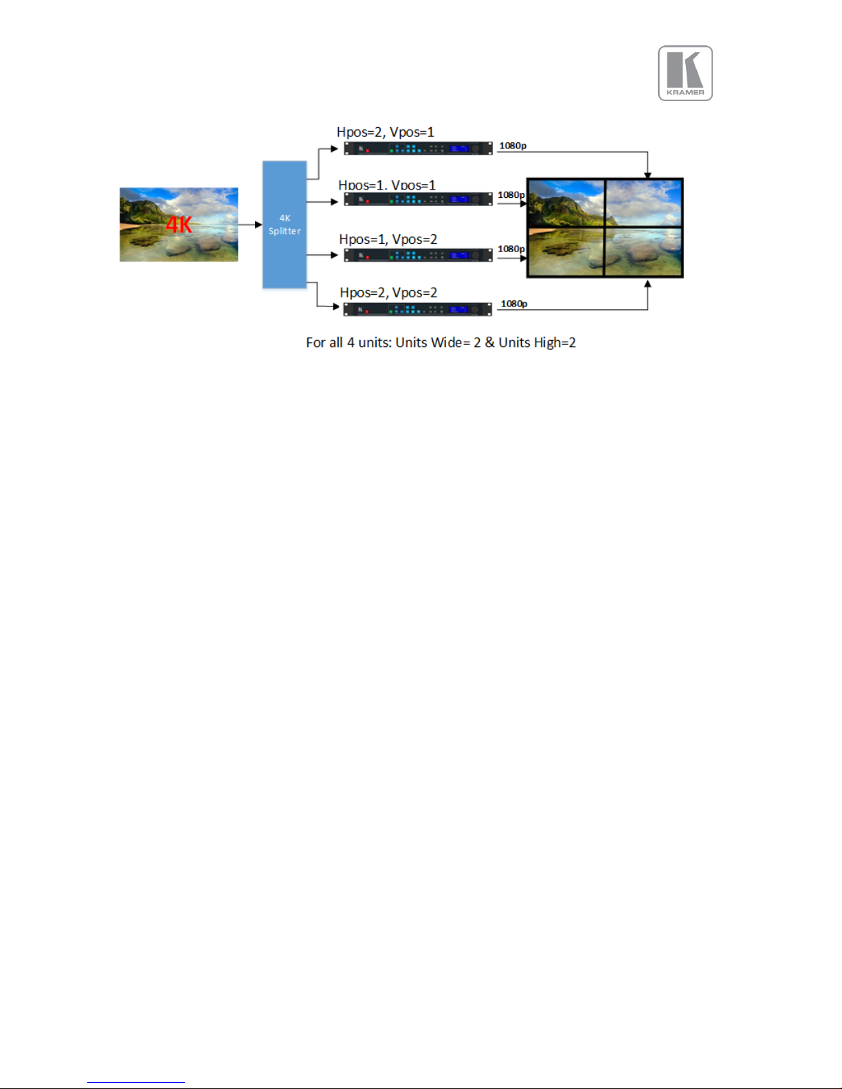
In the example below a 4K image is split into four 1080p quadrants in a 2x2 configuration. Each unit is
set for a 2x2 configuration and I/O lock. Hpos and Vpos setting are set as shown in the drawing.
Page 41
© KRAMER ELECTRONICS LTD.
Issue 1-16 May 30, 2017
41
Figure 2: 2x2 Video Wall example
6.2.4.4 Bezel Width
This menu allows uses to define the bezel widths in large system configuration where multiple units
are driving different portions of the display. There are separate adjustments for each.
Settings: Left Bezel Width, Right Bezel Width, Top Bezel Width, Bottom Bezel Width
Defaults: 0,0,0,0
6.2.4.5 Wall Setup
In a system configuration where multiple units are driving different portions of a large display, each
unit is driving a different portion of the total display. If the size of the different portions of the display
are equal, the settings discussed so far in this section are sufficient to defined the area where the
output image will be displayed.
If the size of the portions are unequal, then the Advanced wall setup needs to be enabled in order to
define the area each portion occupies within the total display space. Standard mode works up to a
wall size of 4x4. Advanced mode is limited to a maximum wall size of 2x2.
Settings: Standard / Advanced
Default : Standard
6.2.4.5.1 Advanced Wall Screen
In this menu, users define the total dimension of the display with the width and height settings.
The portion of the output to be displayed is defined by the Horizontal and Vertical offset settings.
Wall Width : Total Wall width
Wall Height: Total Wall Height
Hor Offset : The horizontal position within the total display space where the image will be place
Ver Offset : The vertical position within the total display space where the image will be place
Page 42
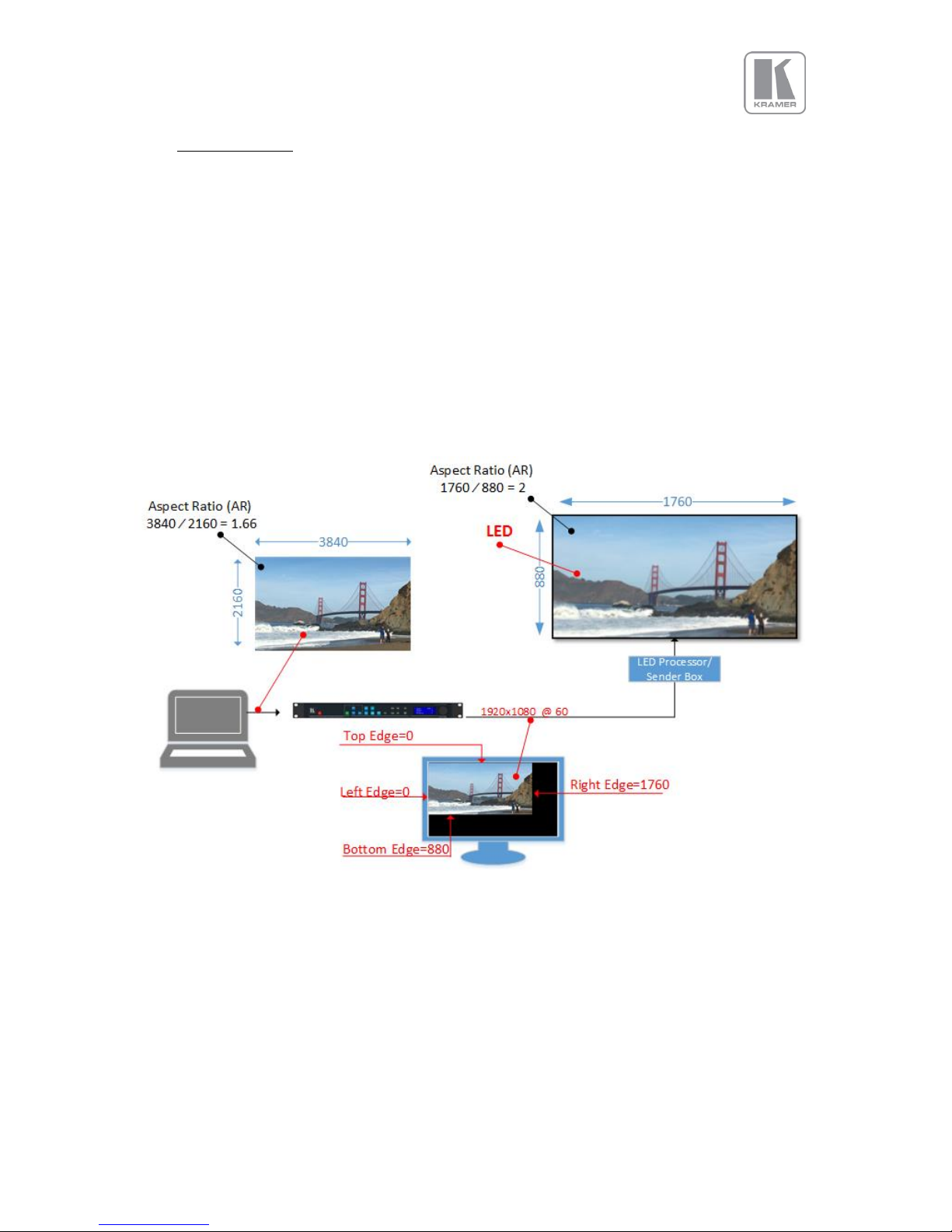
© KRAMER ELECTRONICS LTD.
Issue 1-16 May 30, 2017
42
6.3 LED Screen Setup
This feature is available in VP-798ASV model. With this menu the user can define an area within the
output raster where the output scaled image will be positioned. This area should match exactly the
size of your LED wall. The image size is defined and positioned according to the right, left, top and
bottom edge settings.
The output image can be reduced to as few as 128x96 pixels. The adjustments are performed
horizontally in 4-pixel increments and vertically 1 line increment. If the source is 4K, the horizontal
increment is 8-pixels and vertically is 2 lines. A reset function is also provided to reset all parameters
to full output resolution.
In the example below, the unit is outputting a full resolution of 1920x1080, but the output image is
only present in the corner occupying an area of 1760x880. The LED processor/Sender box that
receives the signal, will only process this area (1760x880 pixels) and transmit it to the LED wall. The
rest of the 1920x1080 area will be ignored, and that is why is left black.
Figure 3: Simple LED Screen Sizing Example
Settings: Left Edge, Right Edge, Top Edge, Bottom Edge
Default: Left Edge=0, Right Edge=Max Horizontal Settings, Top Edge=0, Bottom Edge=Max. Vertical
Setting
Page 43
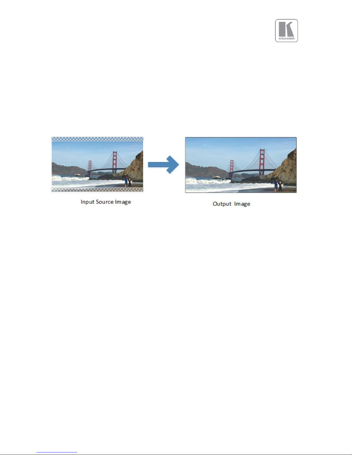
© KRAMER ELECTRONICS LTD.
Issue 1-16 May 30, 2017
43
6.3.1 Few words about Aspect Ratio
In the example above, the aspect ratio of the input source is 1.66, but the LED wall aspect ratio is 2.
When the source and the output aspect ratios do not much, the user has three options. These options
are explained in the Picture Format section that is found under the Input/Geometry chapter of this
document.
In the example, the “Original” option was chosen maintaining the source aspect ratio. With this
option, all objects appear proportional and normal in the output image, but a portion of the source
content was disregarded. As it can be seen in the picture, a small slice of the top and the bottom of
the image has been disregarded.
Figure 4: Maintaining the Aspect Ratio Example
6.3.2 Splicing Zoom
In configurations where multiple units are driving different portions of a large LED wall, each unit
needs to be setup separately. The user needs to define the system configuration, the section of the
LED that each unit will drive and the portion of the image that it will process.
This selection switches on the splicing zoom feature to enable the resizing of the section corresponding
to the unit. When Splicing zoom is turned on, the processor will cut and scale the portion of the picture
selected by the matrix size and position selected as described next. Splicing Zoom should be turned off
when the unit is connected to a multi-head graphics card where the content has been split.
Settings: On/Off
Default: Off
Page 44

© KRAMER ELECTRONICS LTD.
Issue 1-16 May 30, 2017
44
6.3.3 Splicing Width / Splicing Height
This menu defines the dimensions of the LED wall is defined with this menu. The maximum number of
LED screens supported is 16. This function is used in conjunction with the next function.
Settings:
Units Wide: 1, 2, 3, 4
Units High: 1, 2, 3, 4
Default:
Units Wide: 1
Units High: 1
6.3.4 Splicing Horizontal Position (Splicing H-pos) / Splicing Vertical Position (Splicing V-pos)
These settings provide the coordinates of the segment that the unit will process (cut out and resize).
This function is used in conjunction with the previous function.
Settings: 1 to 4 indicating co-ordinates 1,1, to 4,4 for the maximum matrix size of 16
Default : 1, 1
6.3.5 Splicing Setup
In a large LED walls where multiple units are driving different sections of the LED, the sections can be
equal or unequal in size. If the size of the different sections are equal, then the configuration is
standard. For standard configurations the settings discussed so far are sufficient to defined the area
where the output image will be displayed.
If the size of the sections are unequal, then the Advanced splicing setup needs to be enabled in order
to define the size of the area each section.
Standard mode works up to a wall size of 4x4. Advanced mode is limited to a maximum wall size of
2x2.
Settings: Standard / Advanced
Default : Standard
Page 45
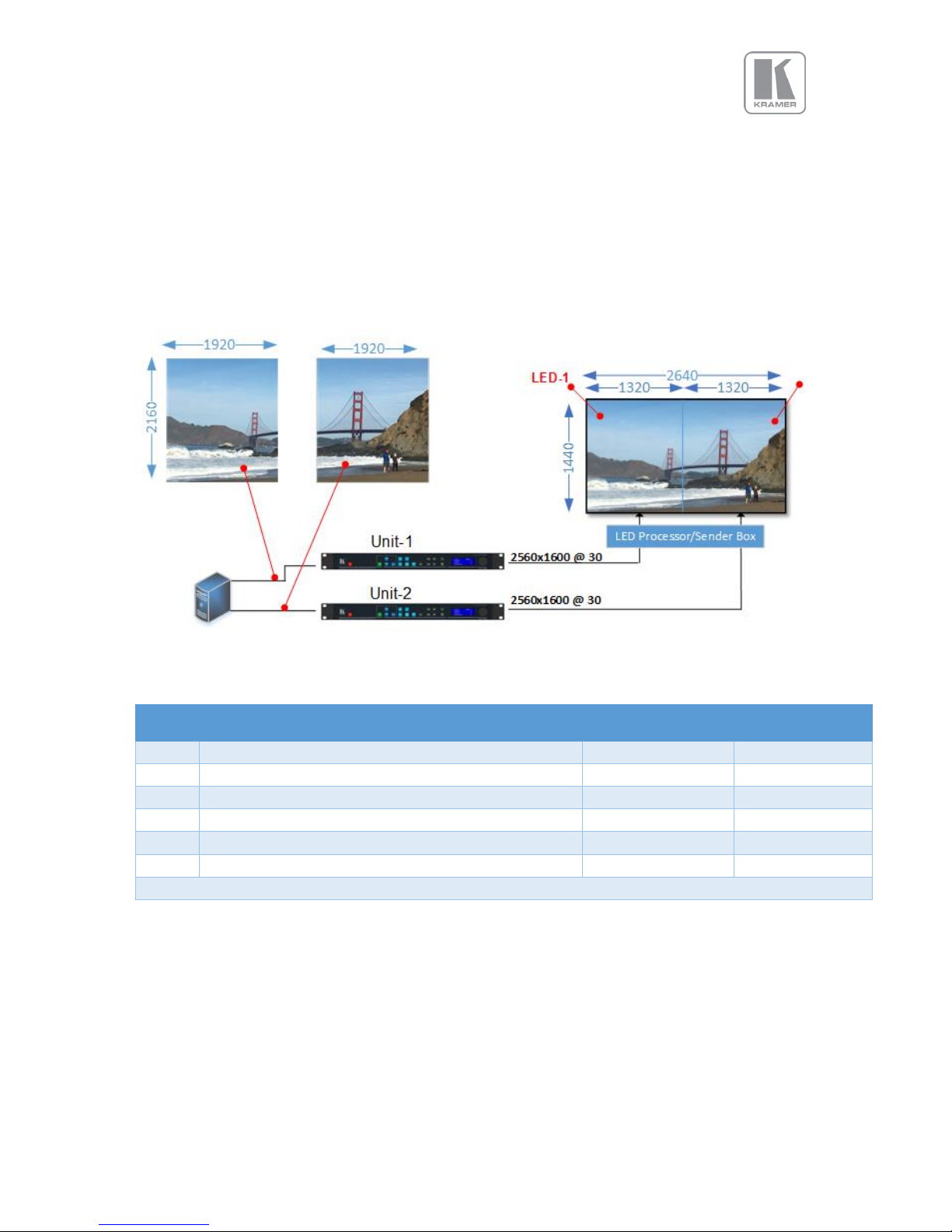
© KRAMER ELECTRONICS LTD.
Issue 1-16 May 30, 2017
45
6.3.6 Standard Splicing
The following figure illustrates how to setup two units in the standard configuration mode.
6.3.6.1 Standard Splicing - 2x1 Example (pre-split source)
The following figure illustrates how to setup two units in the standard configuration mode. In the first
example, the input image is pre-split at the source, so the Splicing Zoom feature is turned Off
Figure 5: Standard Splicing - 2x1 example (pre-split source)
STEP
MENU ITEM TO MODIFY
Unit-1
Unit-2
1
Output>Display Type>I/O Lock
Source
Source
2
LED Screen Size> Splicing Zoom
Off*
Off*
3
LED Screen Size> Splicing Width
1*
1*
4
LED Screen Size> H-Pos
1*
1*
5
LED Screen Size> Right Edge
1320
1320
6
LED Screen Size> Bottom Edge
1440
1440
* Some steps are skipped, because the values are the same as the default settings after factory reset
Page 46
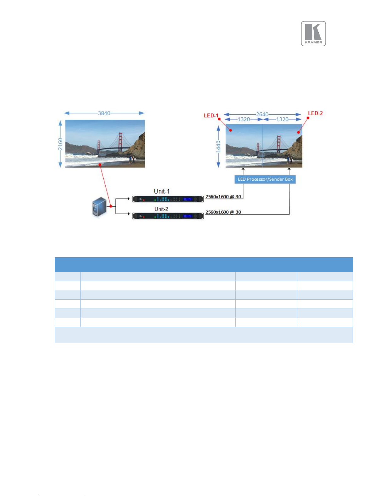
© KRAMER ELECTRONICS LTD.
Issue 1-16 May 30, 2017
46
6.3.6.2 Standard Splicing - 2x1 Example (Split source)
In this and the rest of the examples, it is assumed that the image arrives at each unit from a single
source, so Splicing Zoom is set to On.
Figure 6: Standard Splicing - 2x1 example (common source)
STEP
MENU ITEM TO MODIFY
Unit-1
Unit-2
1
Output>Display Type>I/O Lock
Source
Source
2
LED Screen Size> Splicing Zoom
On
On
3
LED Screen Size> Splicing Width
2
2
4
LED Screen Size> H-Pos
1*
2
5
LED Screen Size> Right Edge
1320
1320
6
LED Screen Size> Bottom Edge
1440
1440
* Some steps are skipped, because the values are the same as the default settings after factory reset
Page 47
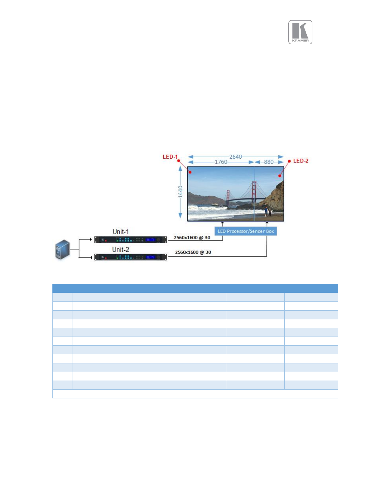
© KRAMER ELECTRONICS LTD.
Issue 1-16 May 30, 2017
47
6.3.7 Advanced Splicing
In this menu, you can define the total dimension of the LED wall with the wall width and height
settings.
The portion of the output to be displayed is defined by the Horizontal and Vertical offset settings. .
Wall Width : Total Wall width
Wall Height: Total Wall Height
Hor Offset : The horizontal position within the total wall space where the image will be place
Ver Offset : The vertical position within the total wall space where the image will be place
6.3.7.1 Advanced Splicing – 2x1 Example
Figure 7: 2x1 Advanced LED Screen Splicing example
STEP
MENU ITEM TO MODIFY
Unit-1
Unit-2
1
Output>Display Type>Output Mode
2560x1600
2560x1600
2
Output>Display Type> Frame Rate
30Hz
30Hz
3
Output>Display Type>I/O Lock
Source
Source
4
LED Screen Size> Splicing Zoom
On
On
5
LED Screen Size> Splicing Width
2
2
6
LED Screen Size> H-Pos
1*
2
7
LED Screen Size> Right Edge
1760
880
8
LED Screen Size> Bottom Edge
1440
1440
10
LED Screen Size> Splicing
Advanced
Advanced
12
LED Screen Size> Advanced Splicing> Wall Width
2640
2640
13
LED Screen Size> Advanced Splicing> Hor. Offset
0*
1760
* Some steps are skipped, because the values are the same as the default settings after factory reset
Page 48
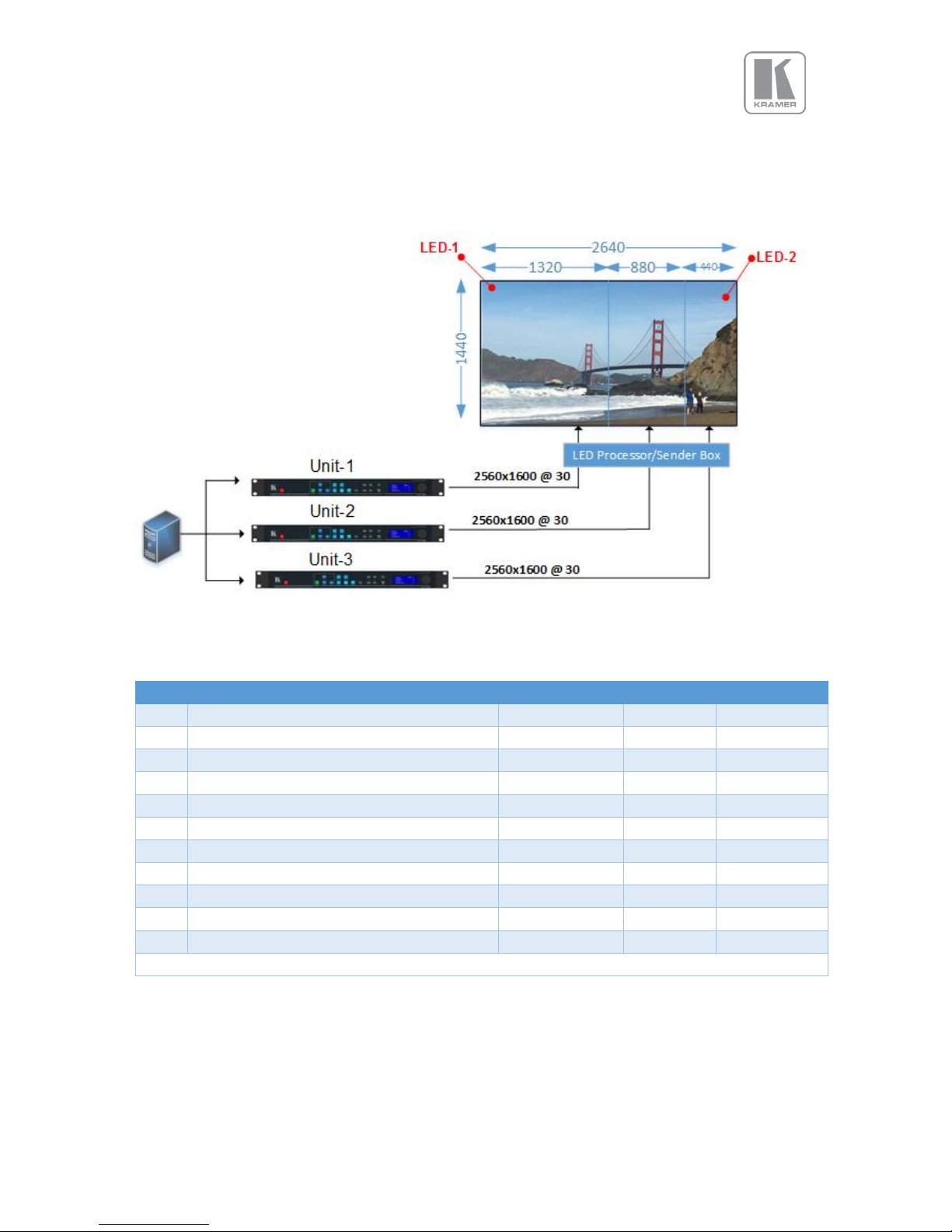
© KRAMER ELECTRONICS LTD.
Issue 1-16 May 30, 2017
48
6.3.7.2 Advanced Splicing – 3x1 Example
Figure 8: Advanced Splicing - 3x1 example
STEP
MENU ITEM TO MODIFY
Unit-1
Unit-2
Unit-3
1
Output>Display Type>Output Mode
2560x1600
2560x1600
2560x1600
2
Output>Display Type> Frame Rate
30Hz
30Hz
30Hz
3
Output>Display Type>I/O Lock
Source
Source
Source
4
LED Screen Size> Splicing Zoom
On
On
On
5
LED Screen Size> Splicing Width
3 3 3
6
LED Screen Size> H-Pos
1* 2 3
7
LED Screen Size> Right Edge
1320
880
440
8
LED Screen Size> Bottom Edge
1440
1440
1440
10
LED Screen Size> Splicing
Advanced
Advanced
Advanced
12
LED Screen Size> Advanced Splicing> Wall Width
2640
2640
2640
13
LED Screen Size> Advanced Splicing> Hor. Offset
0*
1320
2200
* Some steps are skipped, because the values are the same as the default settings after factory reset
Page 49
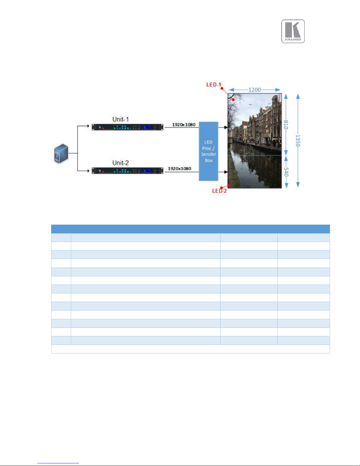
© KRAMER ELECTRONICS LTD.
Issue 1-16 May 30, 2017
49
6.3.7.3 Advanced Splicing – 1x2 Example
Figure 9: Advanced Splicing - 1x2 example
STEP
MENU ITEM TO MODIFY
Unit-1
Unit-2
1
Output>Display Type>Output Mode
1920x1080*
1920x1080*
2
Output>Display Type> Frame Rate
60Hz*
60Hz*
3
Output>Display Type>I/O Lock
Source
Source
4
LED Screen Size> Splicing Zoom
On
On
5
LED Screen Size> Splicing Width
1*
1*
6
LED Screen Size> Splicing Height
2
2
7
LED Screen Size> V-Pos
1*
2
8
LED Screen Size> Right Edge
1200
1200
9
LED Screen Size> Bottom Edge
810
540
10
LED Screen Size> Splicing
Advanced
Advanced
11
LED Screen Size> Advanced Splicing> Wall Width
1200
1200
12
LED Screen Size> Advanced Splicing> Wall Height
1350
1350
13
LED Screen Size> Advanced Splicing> Ver. Offset
0*
810
* Some steps are skipped, because the values are the same as the default settings after factory reset
Page 50

© KRAMER ELECTRONICS LTD.
Issue 1-16 May 30, 2017
50
6.4 System
This selection contains functions which are more applicable to system operation than to picture
adjustment.
6.4.1 User
Several unit settings can be stored under a user name. Different users can store their preferred settings
and recall them by selecting their user name.
User settings are stored automatically and no special action is required by the user. For example, if the
setting is changed from USER1 to USER2, then all of unit’s parameters at the time of the change will be
stored under USER1. When the unit is changed back to USER1, the USER1 settings will be loaded back
to the unit.
Using the Web interface any number of settings can also be stored/restored to/from the PC.
Settings: USER 1, 2, 3, 4, 5, 6, 7, 8, 8, 10
Default : USER 1
6.4.2 Names/Profiles
The Names/Profiles menu provides input masks to rename the generic input channels and user names.
User names and input channel names can be changed to any word with a maximum of 12 alpha numeric
characters with a value range of 0-9, A-Z and blank.
The unit itself can be given a name. The default name is VIDEOPROC. This name followed by the MAC
address is used by the web server and being displayed in the unit line of the webpage.
6.4.3 Menu Settings
This menu allows users to change the menu display time, i.e. the time after which the LCD menu is
switched back to the main status screen again with no user interaction.
From this menu you can change the language and also lock the keyboard. To unlock the keyboard a
combination of keys has to be pressed at the same time. The locking of the keyboard is indicated by a
message that the keypad is locked. The message also specifies the key press combination necessary to
unlock the unit. When successfully unlocking the keypad the message shows up: Keypad unlocked.
The backlight level of the LCD can be set in this menu.
The background colour of the web pages can be changed from dark to light.
6.4.3.1 Language
Settings: English (AE), English (BE), Deutsch
Default: English (AE)
6.4.3.2 Keypad Lock
Settings: Off, Menu Only, All Keys
Default: Lock: Off
Page 51

© KRAMER ELECTRONICS LTD.
Issue 1-16 May 30, 2017
51
6.4.3.3 Menu Time
This is the time the menu remains at the current level when no activity is detected.
Settings: 5, 10, 15, 20, 25, 30, Infinite
Default: 30 secs
6.4.3.4 LCD Backlight
Settings: 0 ..10
Default: 10
6.4.3.5 Jog Push Enable
Settings: On, Off
Default: On
6.4.3.6 Web Colors
Settings: Dark, Light
Default: Dark
Page 52
© KRAMER ELECTRONICS LTD.
Issue 1-16 May 30, 2017
52
6.4.4 Network Settings
The Network Settings menu allows users to configure the unit´s TCP/IP address. Under Address Type a
static or DHCP leased address can be chosen. The static address, gateway address and netmask needs
to be entered manually.
The Network Settings menu provides information on the DHCP Status and IP address assigned to the
unit, as well as the fixed MAC Address programmed into the unit. The DHCP status can be Off when a
static assignment is used. When DHCP is on, the menu displays the leased address. If the lease is
unsuccessful, the menu displays “none”
When changing from DHCP to Static mode or vice versa it is strongly recommended that you cycle the
power to the unit in order the change is properly recognized by other devices on the network.
If you select Static, ensure that the IP address of the computer is on the same network and it has the
same subnet mask and is in the same range as the unit. If the unit is at 169.254.0.1 and the computer
address is at 192.168.215.5, you need to change the unit’s IP address to an address that is in close
range with the computer, for example: 192.168.215.25. The unit’s IP address can be changed with the
rotary wheel. First push knob to enter the edit mode. Then turn the knob to increment or decrement
each digit and press the knob to move the cursor to the next digit. When you finish changing the IP
address, scroll down the menu and select “Apply” for the Network setting changes to become
effective.
Settings: Static, DHCP
Default: DHCP
6.4.5 Security Settings
The password for ftp and web access to the unit can be changed in this menu.
FTP password Default: user
WWW password : Off
6.4.6 Factory Defaults
This button allows users to restore all settings to the default values of the unit, allowing the unit to
return to a known (good) system state. A confirmation is requested prior to actual system settings
restore.
Make sure that no devices on the network that share the same IP address
Factory default does not affect the Network Settings
Page 53

© KRAMER ELECTRONICS LTD.
Issue 1-16 May 30, 2017
53
6.5 Audio
This selection contains functions required to manage the audio inputs and outputs
6.5.1 Mic 1,2 Level, Mix, Mute
The Level setting defines the audio level for the Microphone inputs. Mix adjustment controls the mixing
between Mic and the selected audio source.
Settings:
Level: -12 to +60
Mix : 0 to 100 (100 is full microphone sound)
Mute: Yes, No
Default :
Level: -6
Mix : 50
Mute: No
6.5.2 Balance, Treble, Bass
Balance highlights the sound from the left or right output channels. Treble adjusts high frequency
sounds and bass the low frequency sounds.
Settings:
Balance: -100 to +100
Treble : -15 to +15
Bass: -15 to +15
Default :
Balance: 0
Treble : 0
Bass: 0
6.5.3 Audio Setup
6.5.3.1 Audio Delay
This settings allows the users to adjust the delay between the video and audio sources.
Settings: -100 to 500 ms
Default : 0 ms
6.5.3.2 Input Level
Input level adjusts the gain of the incoming audio signal
Settings: -12 to +6 db
Default : 0 db
Page 54

© KRAMER ELECTRONICS LTD.
Issue 1-16 May 30, 2017
54
6.5.3.3 Input Mode
Defines whether the incoming audio signal is stereo and mono
Settings: Stereo / Mono
Default : Stereo
6.5.3.4 Input Mute
Enables of the mute function for the selected audio source
Settings: Yes / No
Default : No
6.5.3.5 Amp Gain
Amp gain adjusts the gain for the D-power amp driving speakers.
Settings: 0 to +38 db
Default : 0 db
6.5.3.6 Audio Assign
This menu allows users to assign any analog audio source or mics to the selected input. If the selected
input is digital, the user can also select the audio that is embedded to the video signal. These
selections can be performed on per input basis or globally.
6.5.3.6.1 Config
Selects whether the A
udio assignments are done per source or globally
Settings: Per Inp / Globally
Default : Per Inp
6.5.3.6.2 Audio In
This menu is enabled when the audio assignments are done globally. If an Analog source is selected,
the user also choose the analog audio source from the next menu (Analog In). If a Digital source is
selected, the embedded audio in the selected audio source will be used.
Settings: Stereo Analog / Analog with Mic / Digital
Default : Stereo Analog
6.5.3.6.3 Analog In
This menu is enabled when the audio assignments are done globally. From this menu the user selects
the audio source to be assigned to the selected input
Settings: CVBS / HDBaseT / Display Port / HDMI 1 / HDMI 2 / VGA / DVI / HDMI 3
Default : CVBS
Page 55

© KRAMER ELECTRONICS LTD.
Issue 1-16 May 30, 2017
55
6.5.3.6.4 Analog Inputs
This menu is enabled when the audio assignments are done per Input.
For each of the analog video sources the user can select a Stereo Analog source or a Stereo analog
source with the mics. The user can also selected which of the analog source will be assigned to the
input.
Settings: Stereo Analog / Analog with mic
Default : Stereo Analog
For the analog audio source:
Settings: CVBS / HDBaseT / Display Port / HDMI 1 / HDMI 2 / VGA / DVI / HDMI 3
Default : The corresponding analog input associated with the video input
6.5.3.6.5 Digital Inputs
This menu is enabled when the audio assignments are done per Input.
For each of the digital video sources the user can select a Stereo Analog source, a Stereo analog
source with the mics, or the corresponding embedded audio within the video signal. If an analog
source is selected, the user can also selected which of the analog source will be assigned to the input.
Settings: Stereo Analog / Analog with Mic / Digital
Default : Digital
If an analog audio source is selected :
Settings: CVBS / HDBaseT / Display Port / HDMI 1 / HDMI 2 / VGA / DVI / HDMI 3
Default : The corresponding analog input associated with the video input
6.5.3.7 Mic Config
This menu allows users to enable phantom power for condenser mics. When phantom power is
enabled, a voltage of +48V is sent to the condenser microphone via the XLR socket.
6.5.3.8 Audio Out Mute
This menu allows users to mute audio output source individually.
Page 56

© KRAMER ELECTRONICS LTD.
Issue 1-16 May 30, 2017
56
6.6 Status
This menu provides status information of the connections to the HDMI2, DVI/HDMI1 and HDBT outputs.
The unit reads the EDID of the attached monitor and makes decision based on its capabilities and the
configuration of the unit (Deep Colour and HDCP support). The type of attached monitor (DVI or HDMI),
video bit depth (8, 10 or 12 bit per colour channel) and HDCP encryption (on/off) is displayed.
Page 57
© KRAMER ELECTRONICS LTD.
Issue 1-16 May 30, 2017
57
7. Web Browser Control
The unit can be remotely controlled from a PC or any mobile device. No additional software needs to
be installed on the PC. The PC web browser is used as the graphical user interface for all control items.
To connect to the unit the TCP/IP address of the unit has to be entered into the address list box of the
web browser in the following format http://xxx.xxx.xxx.xxx. The TCP/IP address assigned to the unit
can be found in the System/Network Settings menu.
7.1 Connecting to the unit
The Network Settings menu of the unit allows to configure the unit’s TCP/IP address. Under Address
Type a static or DHCP leased address mode can be selected. he factory default of the unit is DHCP. The
static address and Netmask needs to be entered manually.
The Network Settings menu provides information on the DHCP Status and the IP address assigned to
the unit as well as the fixed MAC Address of the unit. The DHCP status is Off when the static
assignment is selected. If the unit has an assigned address, then the menu displays the address, or
“None” if the lease was not successful.
After the correct IP address is entered into the address bar, the web browser starts to load the
menus mirroring the status of the unit. All menu items are shown as their respective buttons, sliders
and list boxes and can be accessed and altered with the PC mouse or corresponding navigational key
presses.
From the web Browser, under security settings, the user name and Password can be turned on. The
default settings are:
User Name: user
Password: user
When changing from DHCP to Static mode or vice versa, it is strongly
recommended that you cycle the power to the unit in order the
change is properly recognized by other devices on the network
Page 58
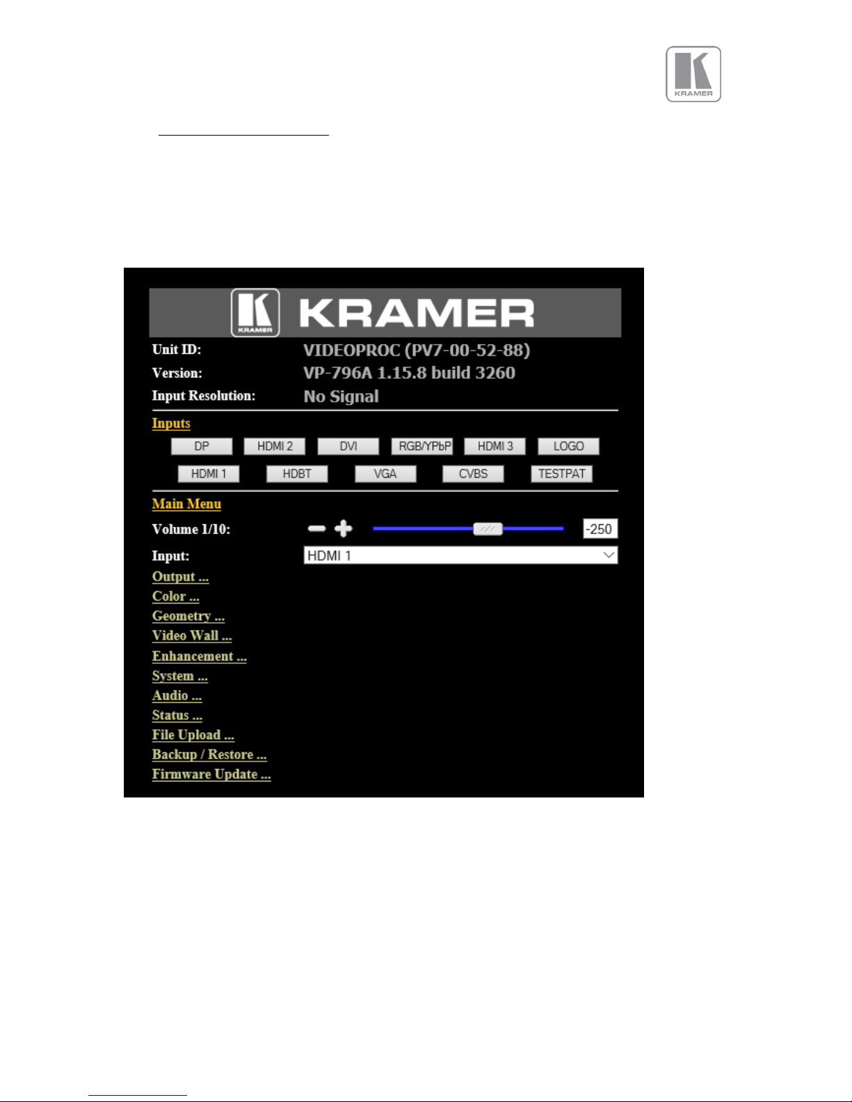
© KRAMER ELECTRONICS LTD.
Issue 1-16 May 30, 2017
58
7.2 Web page menu Orientation
The main page of the web browser is shown below. The Unit ID is displayed on the first line and is
composed of the identifier PV7 followed by the MAC address. The firmware version number and
information on the input mode are listed next.
Under the information pane the available input channels are shown and can be activated directly.
Page 59
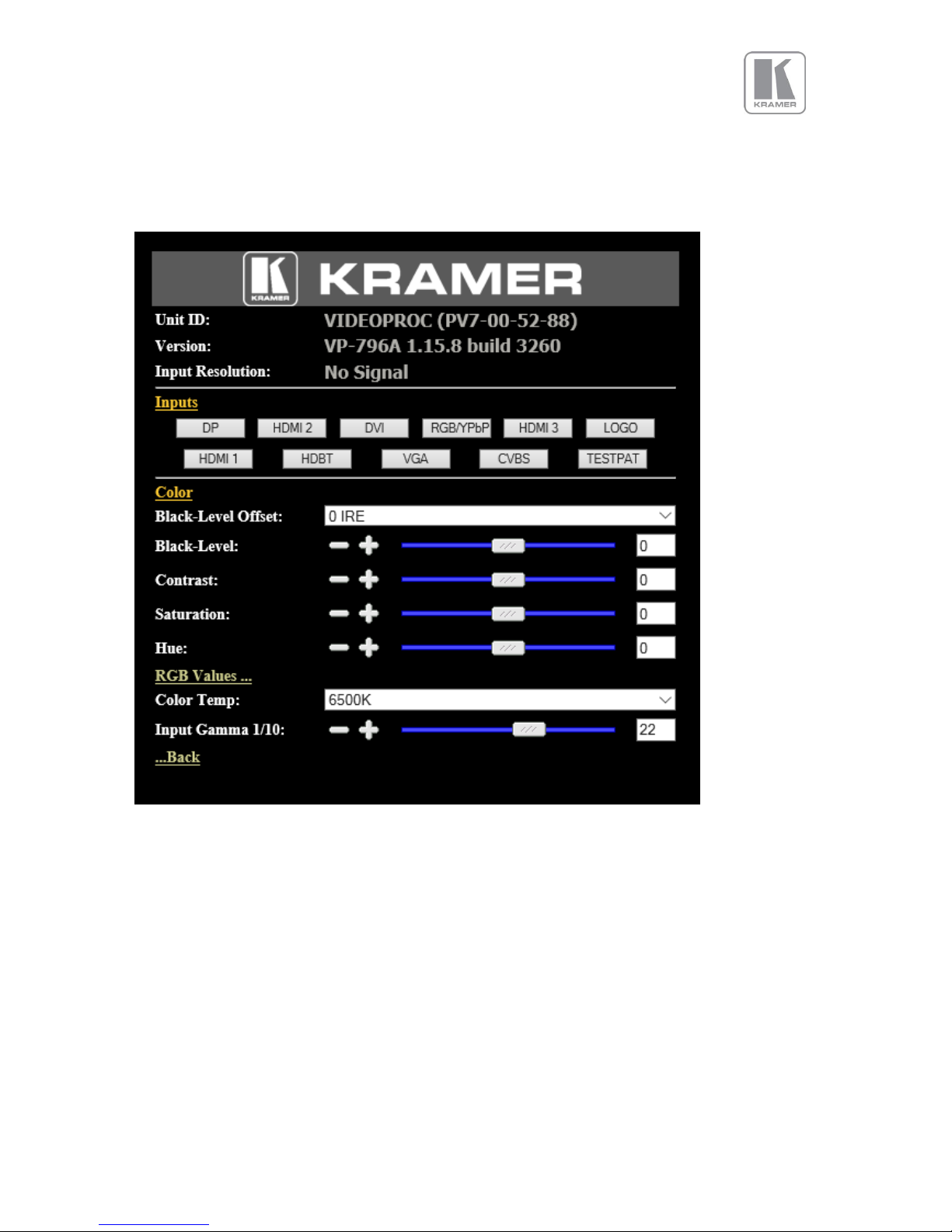
© KRAMER ELECTRONICS LTD.
Issue 1-16 May 30, 2017
59
The menu system can be navigated with the PC mouse. Move the mouse pointer over the menu item
and click the left mouse button to open a submenu. Submenus have three dots followed by the menu
name. Move the mouse pointer over the Back item and click the left mouse button to go back to the
prior menu.
Menu items can be lists, sliders or alpha numeric fields.
A list item can be activated by moving the mouse pointer over the list item and clicking the left mouse
button. The list comes up and an item can be selected by moving the mouse pointer to the desired value
(here: 0 IRE) and clicking the left mouse button again.
A slider value can be changed by moving the mouse pointer over the slider, click and hold the left mouse
button and move the mouse to the right or left to decrease or increase the value. Also, the slider can
be controlled in single steps with the mouse wheel. Or by moving the mouse pointer over the – or +
fields and clicking the left mouse button..
Values can be entered directly in the field beneath the slider. Click into the field, enter the new value
through the PC keyboard and click with the left mouse button to any location outside the field to update
to the new value.
Page 60
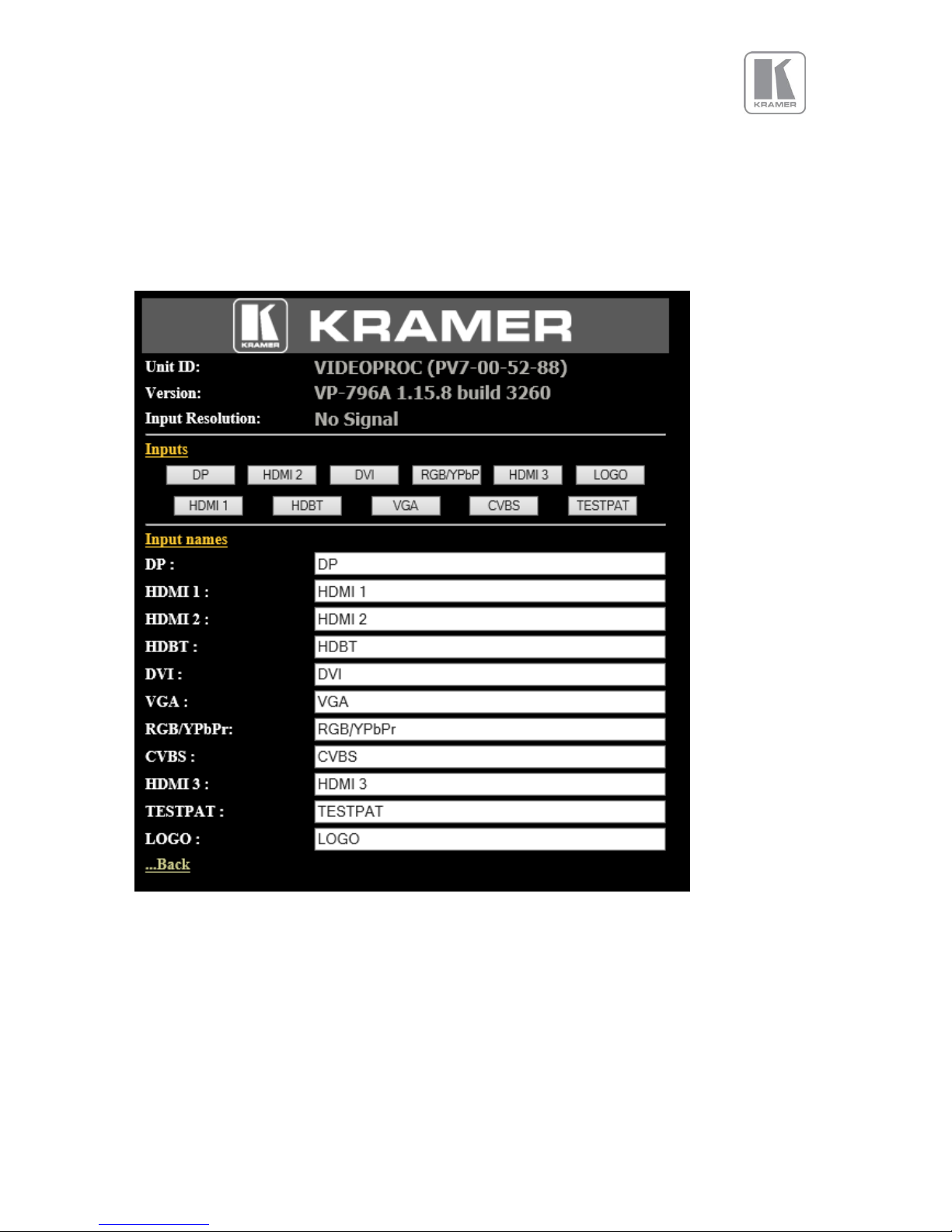
© KRAMER ELECTRONICS LTD.
Issue 1-16 May 30, 2017
60
Renaming the input channel is used as an example to explain the alpha numeric field changes. Move
the mouse pointer into the alpha numeric field and click on the left mouse button. The cursor can be
controlled with the right/left and back space keys of the PC keyboard. The new name for the input
channel can be entered.
The new name is stored when clicking with the left mouse button to any location outside the field.
Page 61
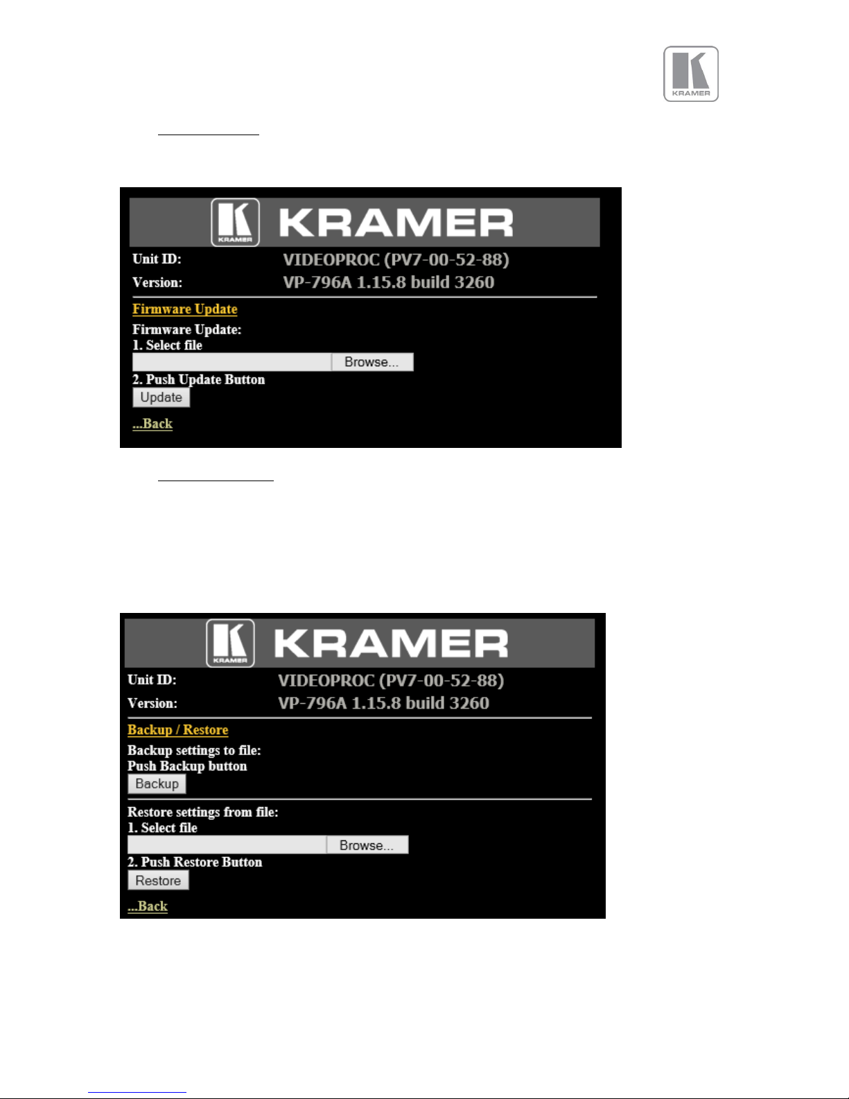
© KRAMER ELECTRONICS LTD.
Issue 1-16 May 30, 2017
61
7.3 Software Update
A page for file uploads is provided. Browse a firmware file (extension .bin) and select it. The path and
name will be shown in the field left to the Browse button. Now click the update button.
7.4 Backup and restore
The unit set-ups can be backed up to a PC and restored later through the web browser When pressing
the Backup button a l file download dialog box appears. The default name of a backup is nvram.bin.
This name can be changed and stored on the PC in any location.
To restore the unit’s settings, browse and select the file on your PC. The selected file will be shown in
the field left to the Browse button. Now press the restore button.
Page 62
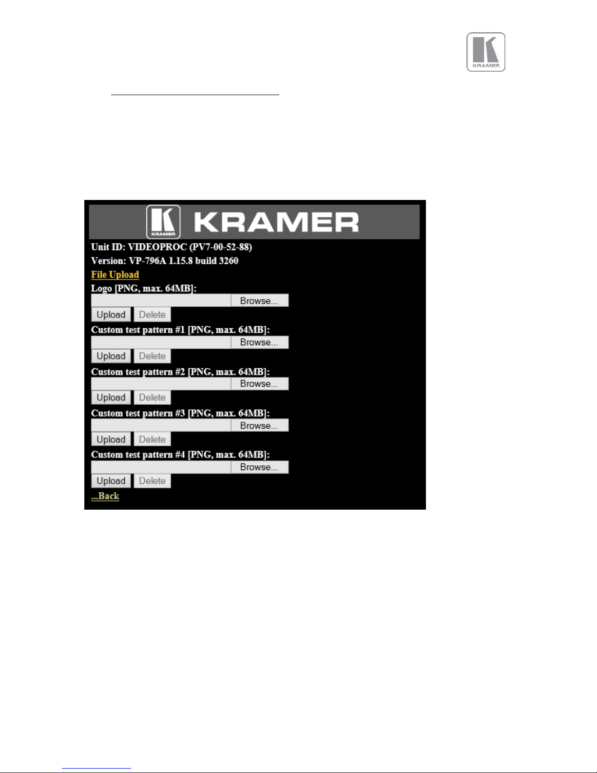
© KRAMER ELECTRONICS LTD.
Issue 1-16 May 30, 2017
62
7.5 LOGO and Custom Test Pattern Capture
Any image in PNG format can be selected from your PC and loaded to the unit to be used as a LOGO.
This name can be changed and stored on the PC in any location. The image size limitation is 64MB.
From the same menu you can select up-to four images and download them as custom test patterns.
These images will appear as Custom1,2,3 or 4 in the Test pattern menu
Page 63
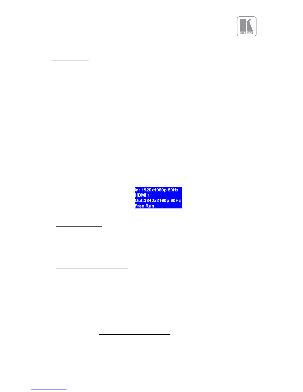
© KRAMER ELECTRONICS LTD.
Issue 1-16 May 30, 2017
63
8. Firmware Update
The latest firmware is found on Kramer’s download website at:
There are two methods of updating your unit’s firmware. First, through a USB port with a USB
memory drive and second, through TCP/IP connection with the web server.
8.1 USB update
▪ From the firmware dropdown menu, select the
“PV7S PQV6xx_HQU7xx_LED7xx‐2\xxxx.bin” file
where XXXX is the latest firmware built number.
▪ Download the .bin file and rename it “PV7update.bin”
▪ Copy the file to the root directory of a USB memory stick
▪ Power Off the unit and plug the USB drive into one of the USB ports
▪ Power On the unit and wait few seconds for the message to remove the USB drive
▪ After the USB is removed, the unit will continue the boot-up process.
▪ Wait until the boot up processes is completed, and the status menu appears on the front
panel screen. The Status menu indicates the detected source, Output resolution and I/O lock
state.
8.2 Web Browser update
To update via the web server, please follow the steps outlined previously in the web browser control
chapter.
8.3 System restore from an image file
If power is lost during the update procedure, the unit may fail to complete the process and even fail to
bootup. In this case, the system software can be restored to a previous version using an image file found
on the website.
• Download the pv7.restore.img file to your computer. Be aware that this is a large file,
approximately 130MB, and depending on your internet connection the download time may be
long.
▪ Copy the file to the root directory of a USB memory stick
▪ Power Off the unit and plug the USB drive into one of the USB ports
▪ Power On the unit while pressing the Standby button on the front panel
▪ Keep the Standby button pressed and wait a few seconds until a message appears asking you
to remove the USB drive
Page 64

© KRAMER ELECTRONICS LTD.
Issue 1-16 May 30, 2017
64
▪ After the USB is removed, the unit will continue the restore and boot-up process.
▪ When the boot up process is completed, the status menu will appear on the front panel
screen.
▪ Press the Esc button and while the button is pushed in, press the Standby button to view the
software version loaded into the unit. Hit the Menu Sel button to exit to the Status menu
Next, follow either of the methods described earlier in this chapter to update the unit to the latest
software release.
Page 65

© KRAMER ELECTRONICS LTD.
Issue 1-16 May 30, 2017
65
9. ENVIRONMENTAL AND EMC
9.1 Recommended Operating Conditions
Temperature 0oC to 40oC
Humidity (non-condensing) 5% to 95%
9.2 Storage
Temperature -25oC to +85oC
Humidity 0% to 95%
9.3 CE and FCC Compliance
CE: This product complies with the requirements of 2004/108/EC Electromagnetic
Compatibility Directive, and 2006/95/EC Low Voltage Directive. Compliance is to EN55022
Class A.
FCC: WARNING: This equipment has been tested and found to comply with the limits for a Class
A digital device pursuant to Part 15 of the FCC Rules. These limits are designed to provide
reasonable protection against harmful interference when the equipment is operated in a
commercial environment. This equipment generates uses and can radiate radio frequency
energy and, if not installed and used in accordance with the instruction manual, may cause
interference to radio communications. Operation of this equipment in a residential area is
likely to cause interference in which case the user will be required to correct the
interference at their own expense.
The user is cautioned that changes and modifications made to the equipment without
approval of the manufacturer could void the user’s authority to operate this equipment.
It is suggested that the user use only shielded and grounded signal cables to ensure
compliance with FCC rules.
9.4 PAT Testing
Earth continuity testing under PAT regulations shall be done to the product with 8A or 10A only. A test
with 25A may damage the product.
Since the unit is classified as an IT equipment, according to the IEE Code of Practice, the test can also
be performed with 20-200mA. If this method is not available, and a high current test is to be used
instead, a 8A or 10A test is also acceptable (a minimum of 1.5 times of the unit’s internal 5A fuse).
Always connect the test lead (mains earth) to the metal chassis. DO NOT CONNECT to the connectors
of the rear panel (signal earth), because you may damage the unit beyond repair. This type of damage
is not covered by warranty.
Page 66

© KRAMER ELECTRONICS LTD.
Issue 1-16 May 30, 2017
66
APPENDIX A: FRONT PANEL MENU TREE STRUCTURE
After the unit boots up, the Status menu is presented on the front panel display. The user can enter
the main menu by pressing the MenuSel button or the jog wheel.
The Main Menu tree is composed of the following sections :
• Input
• Output
• LED Screen Size (VP-798ASV model only)
• PIP* (not available in VP-796(A)(ASV) Models)
• System
• Status
• Audio (Audio Models: Extensive audio menu is presented in Appendix B )
* Future software release
Page 67
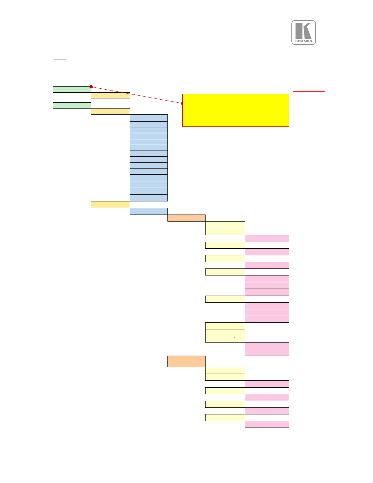
© KRAMER ELECTRONICS LTD.
Issue 1-16 May 30, 2017
67
Input
Input Menu
Volume
Factory Defaults
0 .. 63.5 db
Input
HDMI-1
Source
3GSDI-1*
3GSDI-2*
DisplayPort
HDMI-1
HDMI-2
IP Video*
HDBT*
VGA
DVI
CV
RGB/YPbPr
HDMI-3
TP
LOGO
Input Config
Analog Inputs
VGA Setup
Clock
0
Phase
0
0 ... 31 steps
H-Position
0
0
V-Position
0
-3 .. +3
ColorSpace
RGB
RGB
YCbCr
Auto
Range
Full
Full
Limited
Auto
Reset Mode
EDID IN
1920x1080p
640x480p
... 2048x1200p
RGB/YPbPr
Setup
Clock
0
Phase
0
0 ... 31 steps
H-Position
0
0
V-Position
0
0
ColorSpace
RGB
RGB
Volume adjustment is only available in
the Audio models. For the complete
Audio Menu, refer to the next section
Page 68
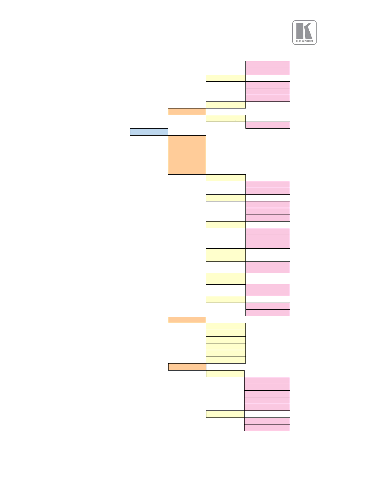
© KRAMER ELECTRONICS LTD.
Issue 1-16 May 30, 2017
68
Input Menu
YCbCr
Auto
Range
Full
Full
Limited
Auto
Reset Mode
CVBS Setup
CCS
On
Off / On
Digital Inputs
DP Config
HDMI-1 Config
HDM-2 Config
HDBT Config*
DVI Config
HDMI-3 Config
Colorspace
RGB
RGB
YCbCr
Range
Auto
Auto
Full
Limited
Deep Color
Auto
Auto
On
Off
EDID In (for DP,
HDMI1&2&HDBT)
3840 x 2160p
640x480p to
4096 x 2160 p
EDID In (for DVI
& HDMI-3
1920x1080p
640x480p to
2560x1080p
HDCP
On
On
Off
HDMI Audio
Full
Full
Match Display 1
Match Display 2
S/PDIF friendly
SDI friendly 2-ch
SDI friendly 8-ch
SDI Setup*
Stereo ch(1,2)
Audio Map
Stereo ch(1,2)
Stereo ch(3,4)
Stereo ch(5,6)
Stereo ch(7,8)
Multichannel
Level B priority
SDI 1
SDI 1
SDI 2
Page 69
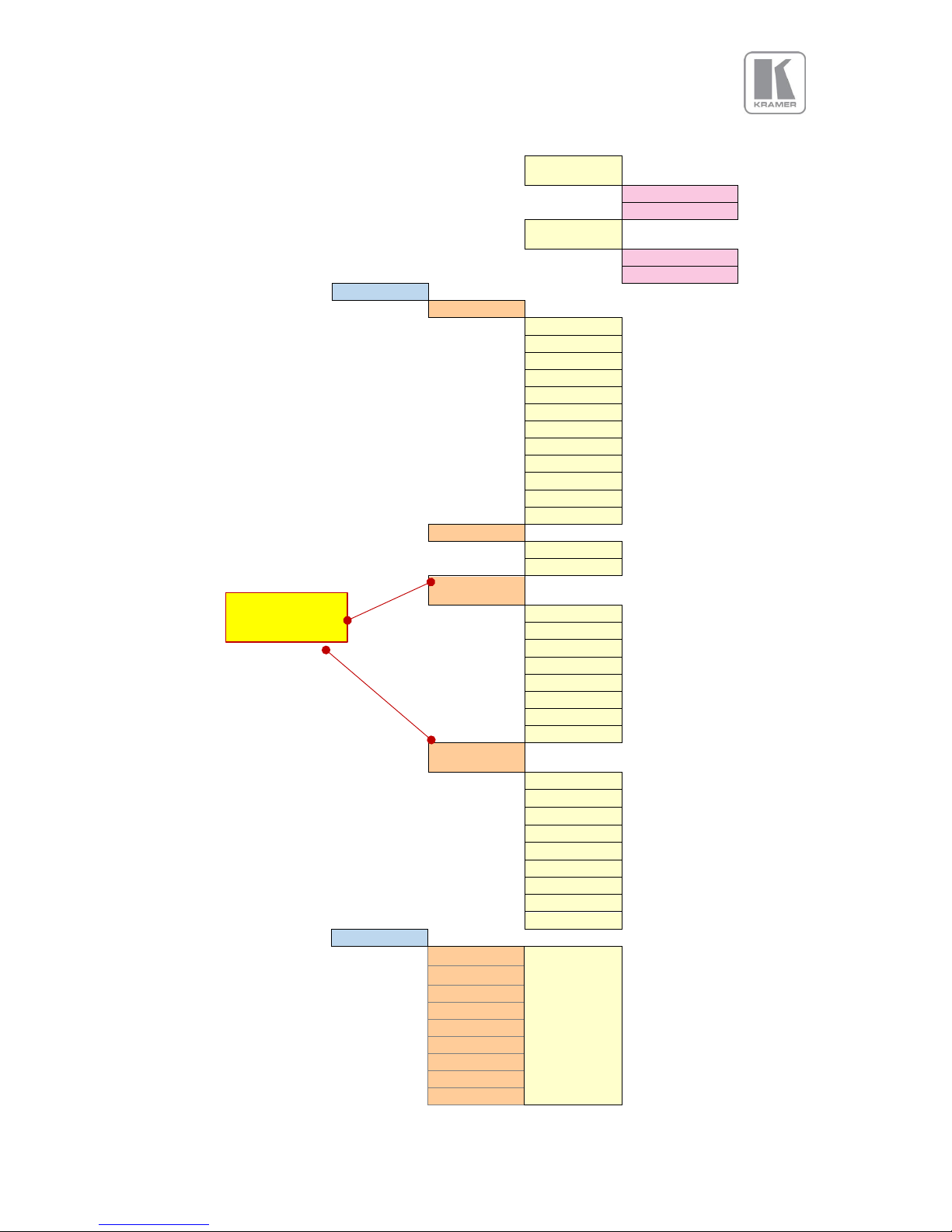
© KRAMER ELECTRONICS LTD.
Issue 1-16 May 30, 2017
69
Input Menu
SDI-1 Level B
Strm
Stream 1
Stream 1
Stream 2
SDI-2 Level B
Strm
Stream 1
Stream 1
Stream 2
TP Setup
SMPTE
Test Pattern
Red curtain
Green curtain
Blue curtain
Grey V bars
Grey H bars
Aspect Test
Multi Test
Warp Adjust
SMPTE
PLUGE
Moving Cross
Custom 1,2,3,4
Test Tone
Off
On
Off
Foreground
Color
White
Black
White
Yellow
Cyan
Green
Magenta
Red
Blue
Background
Color
Multi
Black
White
Yellow
Cyan
Green
Magenta
Red
Blue
Multi
Input Enable
On
3GSDI-1*
On
Off
3GSDI-2 *
DisplayPort
HDMI-1
HDMI-2
HDBT*
VGA
DVI
CV
Moving Cross
adjustments
Page 70
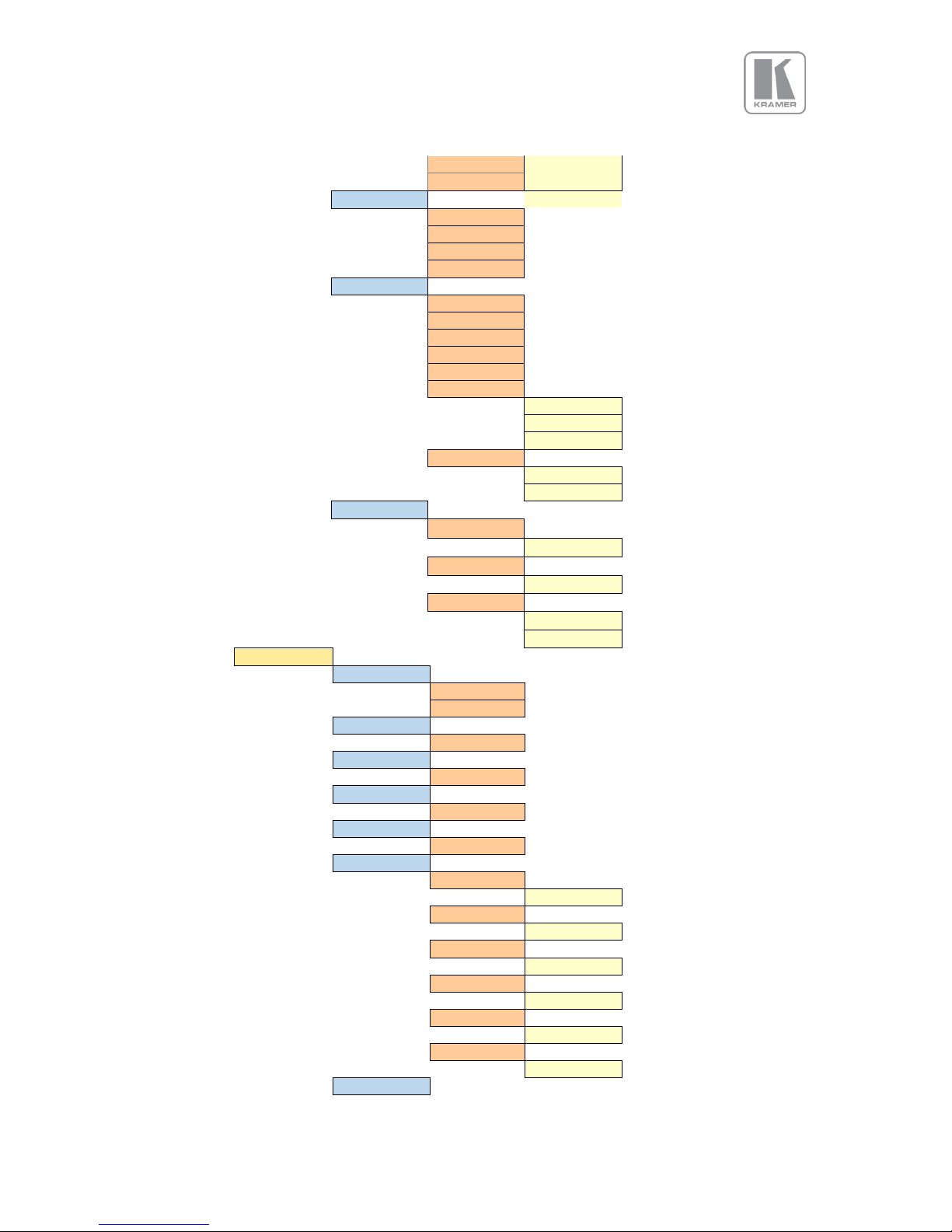
© KRAMER ELECTRONICS LTD.
Issue 1-16 May 30, 2017
70
Input Menu
RGB/YPbPr
HDMI-3
Switching Trans.
Freeze
Freeze
Blank
Fast Fade
Slow Fade
Video Streaming
Freeze
IP Address
Port
Name
Start
Stop
Auto Start
Off
Button
Bootup
Auto Reconnect
Off
On
Custom Modes
CM 1-4 Width
640 to 4096
1920
CM 1-4 Height
480 to 2160
1080
CM 1-4 Type
Progressive
Progressive
Interlaced
Color
BL-Offset
0 IRE
0 IRE
7.5 IRE
Brightness
0
-50 ... 50 steps
Contrast
0
-50 ... 50 steps
Saturation
0
-50. ... 50 steps
Hue
0
-50 ... 50 steps
RGB Values
Red Bias
0
-512 ... 512
Red Gain
0
-512 ... 512
Green Bias
0
-512 ... 512
Green Gain
0
-512 ... 512
Blue Bias
0
-512 ... 512
Blue Gain
0
-512 ... 512
Color Temp
6500K
Page 71
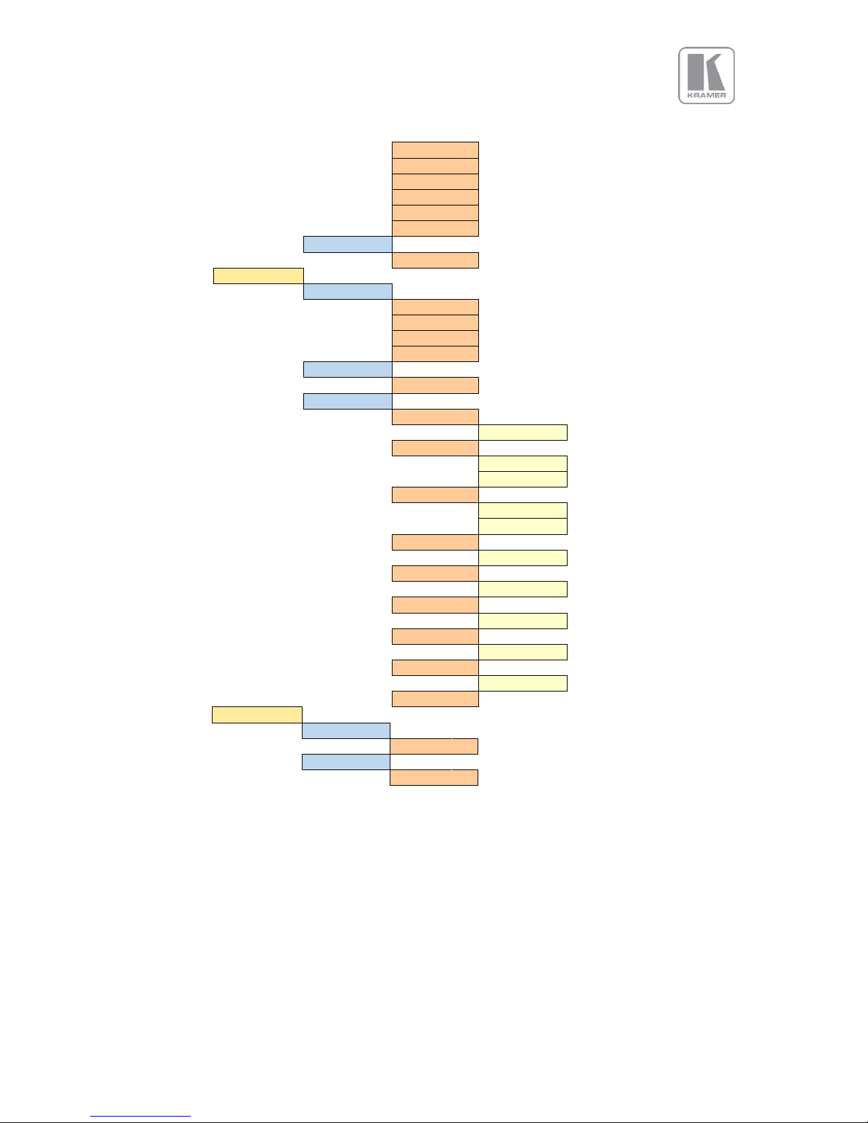
© KRAMER ELECTRONICS LTD.
Issue 1-16 May 30, 2017
71
Input Menu
3200K
3700K
5500K
6500K
7500K
9300K
Input Gamma
1.0
1.0 ... 3.0
Geometry
Pict. Format
Full Screen
Original
Full Screen
Crop
Anamorphic
Overscan
0
0%.. 10%
Pan/Tilt/Zoom
PTZ Enable
Off
Off, On
PTZ Setting
Per Input
Global
Use per-mode
PTZ Value
Pixels
Pixels
Percent
Pan
0
-50% ... 50%
Tilt
0
-50% ... 50%
Zoom H
0
25% - 400%
Aspect Lock
On
Off, On
Zoom V
0
25% ...400%
PTZ Reset
Enhancement
Sharpness
0
-4 ... 4 steps
Details
0
0 ... 3 steps
Page 72
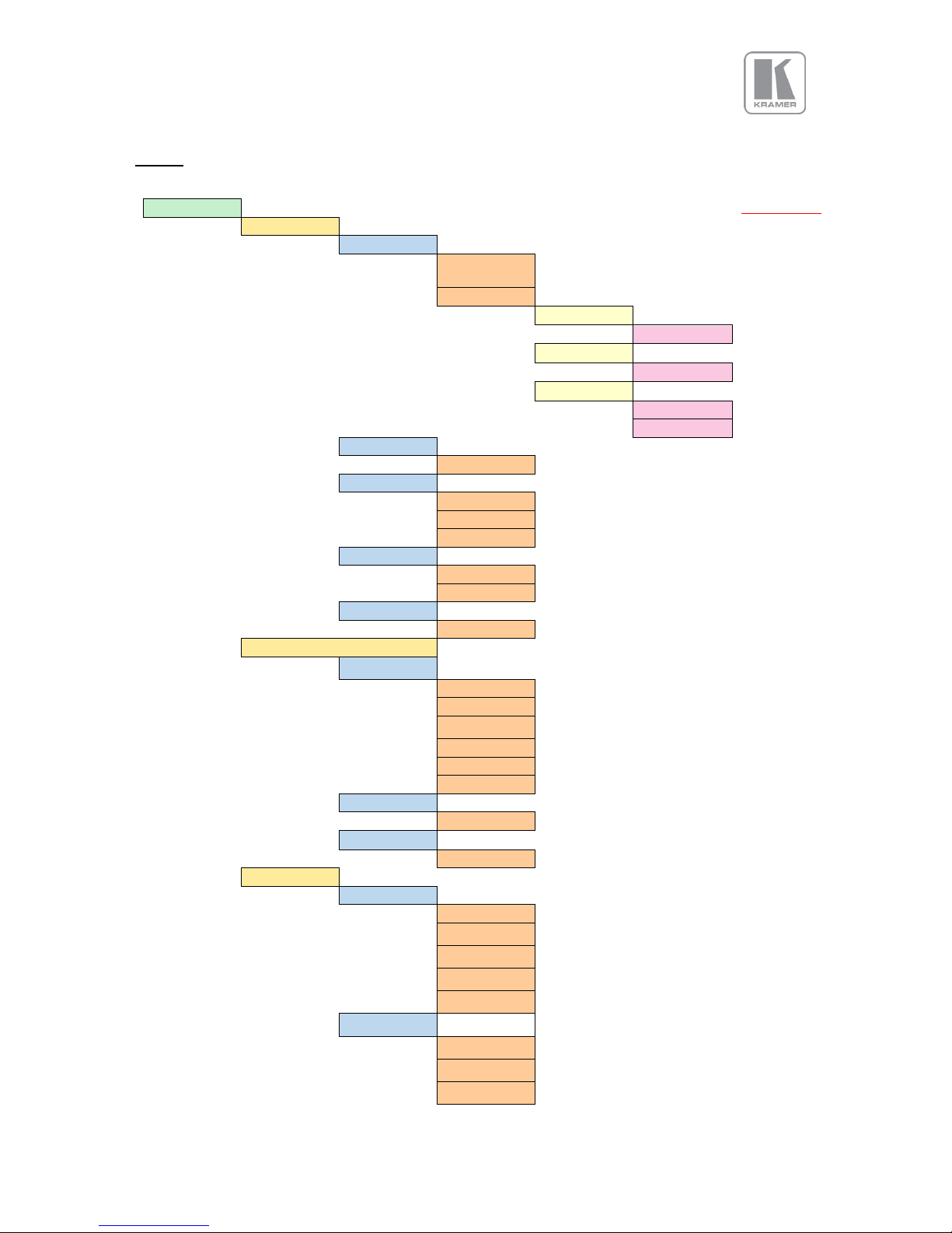
© KRAMER ELECTRONICS LTD.
Issue 1-16 May 30, 2017
72
Output
Output Menu
Output
Factory Defaults
Display Type
O/P Mode
1920x1080p
640x480p.....
4096x2160p
Custom 1 -4*
CM 1-4 Width
640 to 4096
1920
CM 1-4 Height
480 to 2160
1080
CM 1-4 Type
Progressive
Progressive
Interlaced
Frame Rate
59.94Hz
23.98Hz ... 60Hz
I/O Lock
Off
Off
Source
Genlock
Genlock Offsets
H Offset
V Offset
FR Enable
Yes / No
Gamma/ Color/ Crush
Native Color
6500K
3200K
3700K
5500K
6500K
7500K
9300K
Output Gamma
1.0
1.0 ... 3.0
Black Crush*
0
0 .. 255 steps
Output Config
HDMI Output
DVI/HDMI
HDMI
DVI Forced
HDMI 8-bit
HDMI-10bit
HDMI 12-bit
DVI Output
DVI/HDMI
DVI Forced
HDMI 8-bit
Page 73
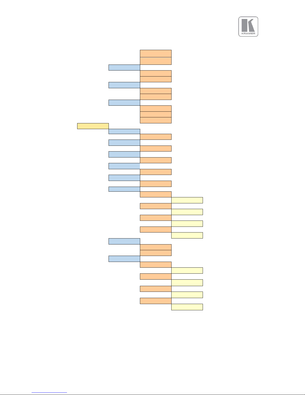
© KRAMER ELECTRONICS LTD.
Issue 1-16 May 30, 2017
73
Output Menu
HDMI-10bit
HDMI 12-bit
HDCP
On
On
Off
Color space
RGB
RGB
YPbPr
Range
Auto
Full
Limited
Auto
Video Wall
Auto Zoom
Off
Off, On
Units Wide
1
1,2,3,4
Units High
1
1,2,3,4
H-Position
0
1,2,3,4
V-Position
0
1,2,3,4
Bezel Width
L(eft) Bezel
0
0 pxls ... 50pxls
R(ight) Bezel
0
0 pxls ... 50pxls
T(op) Bezel
0
0 pxls ... 50pxls
Bot(tom) Bezel
0
0 pxls ... 50pxls
Wall Setup
Standard
Standard
Advanced
Adv. Wall Setup
Wall Width
0 pxls ...3840pxls
Wall Height
0 pxls ...2160pxls
Hor Offset
0 pxls ...3840pxls
Ver Offset
0 pxls ...2160pxls
Page 74
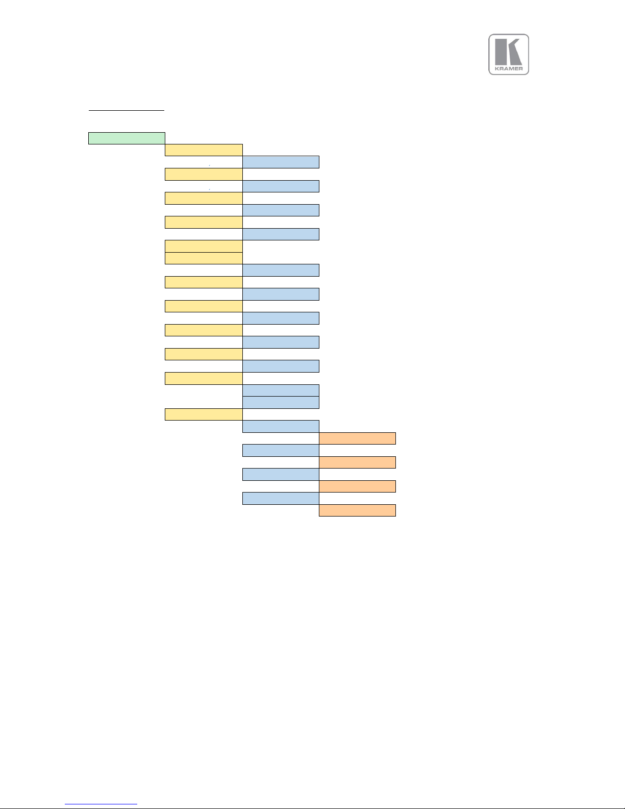
© KRAMER ELECTRONICS LTD.
Issue 1-16 May 30, 2017
74
LED Screen Sizing
LED Size Menu
LED Screen Size*
Left Edge
0
0... 4096
Right Edge
Hmax
0... 4096
Top Edge
0
0... 2160
Bottom Edge
Vmax
0... 2160
LED Screen Reset
Splicing Zoom
Off
Off / On
Splicing Width
1
1,2,3,4
Splicing Height
1
1,2,3,4
Splicing H-Pos
1
1,2,3,4
Splicing V-Pos
1
1,2,3,4
Splicing Setup
Standard
Standard
Advanced
Advanced Splicing
Wall Width
0 pxls ... 3840pxls
Wall Height
0 pxls ... 2160pxls
Hor Offset
0 pxls ... 3840pxls
Ver Offset
0 pxls ... 2160pxls
Page 75
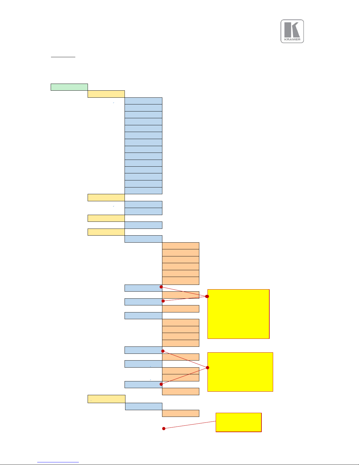
© KRAMER ELECTRONICS LTD.
Issue 1-16 May 30, 2017
75
PiP Menu
PIP Menu
PIP*
PIP Input
LOGO
3GSDI-1
3GSDI-2
DisplayPort
HDMI-1
HDMI-2
IP Video
HDBT
VGA
DVI
CV
RGB/YPbPr
HDMI-3
TEST PATTERN
LOGO
PIP Mode
PIP
Off
PIP
Overscan
0
0 ... 10
PIP Pos/Size
PIP Position
Top Left
Top Left
Top Right
Bottom Left
Bottom Right
Center
Free H/V
PIP H-Pos
0
0 ... Hmax
PIP V-Pos
0
0 ... Vmax
PIP Size
Medium
Small
Medium
Large
Free H/V
PIP Width
0 ... Hmax
Aspect Lock
On
Off
On
PIP Height
0 ... Vmax
Pan/Tilt/Zoom
PTZ Enable
Off
Off
Enabled when Free
H/V for PIP Position is
selected. These
settings interreact
with PIP Width and PIP
Height
Enabled when Free H/V
for PIP Size is selected.
These settings interreact
with PIP H-Pos and PIP
V-Pos
Enabled when
PTZ is enabled
Page 76
© KRAMER ELECTRONICS LTD.
Issue 1-16 May 30, 2017
76
PIP Menu
On
PTZ Setting
Global
Global
Per-input
Per-input permode
Pan
0
-50% ... 50%
Tilt
-50% ... 50%
Zoom H
0
0 .. Hmax
Aspect Lock
Off
On
On
Zoom V
0 .. Vmax
0
PTZ Reset
Color
Black-Level
Offset
0 IRE
0 IRE
7.5 IRE
Brightness
-50 ... 50
0
Contrast
-50 ... 50
0
Saturation
-50 ... 50
0
Hue
-50 ... 50
0
Enabled when
Aspect Lock is Off
Page 77
© KRAMER ELECTRONICS LTD.
Issue 1-16 May 30, 2017
77
System
System
System
Names/Profiles
Unit Name
Input Names
3GSDI-1
3GSDI-2
DisplayPort
HDMI-1
HDMI-2
HDBT
IP Video
VGA
DVI
CV
RGB/YPbPr
HDMI-3
TestPattern
LOGO
User Names
User 1 ...User 10
Menu Settings
Language
English (AE)
English (AE)
English (BE
Deutsch
Keypad Lock
Off
Off
Menu Only
All Keys
Menu Time
30 sec
5 sec
10 sec
15 sec
20 sec
25 sec
30 sec
Infinite
LCD Backlight
10
0 ..10
Jog Push Enable
On
On
Off
Web Colors
Dark
Dark
Light
Network
Settings
Address Type
DHCP
DHCP
Static
Page 78
© KRAMER ELECTRONICS LTD.
Issue 1-16 May 30, 2017
78
System
IP
NET
GW
Apply
Security Settings
FTP Passwd
user
user
WWW Passwd
Off
On
Off
Factory Defaults
Cancel
Factory Defaults
Status
Status
HDMI
HDCP
Bit Depth
8,10,12
DVI
HDCP
Bit Depth
8,10,12
HDBT
HDCP
Bit Depth
8,10,12
Audio
Audio Delay
0
-100 .. 500 ms
This menu is present
in non-audio models.
The Audio menu for
the Audio models is
presented in the next
section
Page 79
© KRAMER ELECTRONICS LTD.
Issue 1-16 May 30, 2017
79
APPENDIX B: FRONT PANEL AUDIO MENU TREE STRUCTURE
Audio Menu
Audio
Mic1 Level
-6.0 ... 60.0
Mic1 Mix
0 ... 100 %
Mic1 Mute
No/ Yes
Mic2 Level
`
-6.0 ... 60.0 db
Mic2 Mix
0 ... 100 %
Mic2 Mute
No/ Yes
Balance
-100 ... 100
Treble
-15.0 ... 15.0
Bass
-15.0 ... 15.0
Audio Setup
Audio Delay
-100 ... 300 ms
Input Level
-12.0 ... 6.0 db
Input Mode
Stereo / Mono
Input Mute
No / Yes
Amp Gain
0 ... 39
Audio Assign
Config
Per Input
Global
Audio In
Stereo Analog
Analog with Mics
Digital
Page 80
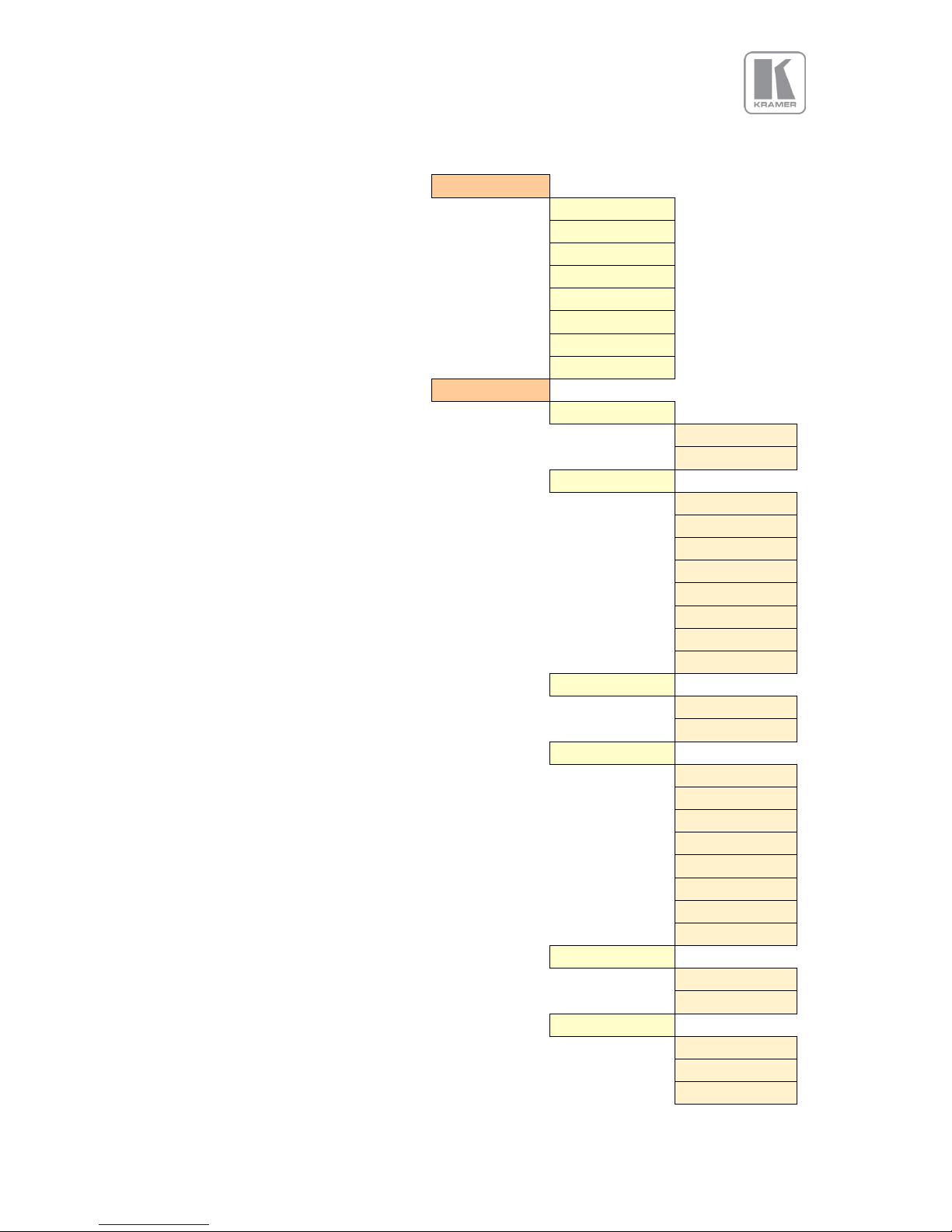
© KRAMER ELECTRONICS LTD.
Issue 1-16 May 30, 2017
80
Audio Menu
Analog In
CVBS
Display Port
HDMI 1
HDMI 2
VGA
DVI
HDMI 3
HDBaseT
Analog Inputs
VGA Audio
Stereo Analog
Analog with Mics
VGA Analog
CVBS
Display Port
HDMI 1
HDMI 2
VGA
DVI
HDMI 3
HDBaseT
RGB/YPbPr Audio
Stereo Analog
Analog with Mics
RGB/YPbPr Analog
CVBS
Display Port
HDMI 1
HDMI 2
VGA
DVI
HDMI 3
HDBaseT
CVBS Audio
Stereo Analog
Analog with Mics
CVBS Analog
CVBS
Display Port
HDMI 1
Page 81
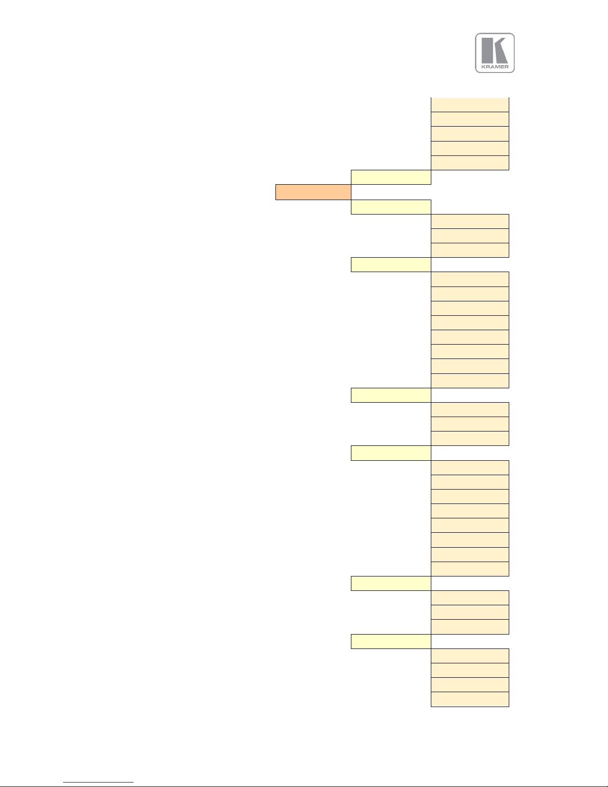
© KRAMER ELECTRONICS LTD.
Issue 1-16 May 30, 2017
81
Audio Menu
HDMI 2
VGA
DVI
HDMI 3
HDBaseT
Exit
Digital Inputs
SDI1 Audio
Stereo Analog
Analog with Mics
Digital
SDI1 Analog
CVBS
Display Port
HDMI 1
HDMI 2
VGA
DVI
HDMI 3
HDBaseT
SDI2 Audio
Stereo Analog
Analog with Mics
Digital
SDI2 Analog
CVBS
Display Port
HDMI 1
HDMI 2
VGA
DVI
HDMI 3
HDBaseT
DP Audio
Stereo Analog
Analog with Mics
Digital
DP Analog
CVBS
Display Port
HDMI 1
HDMI 2
Page 82
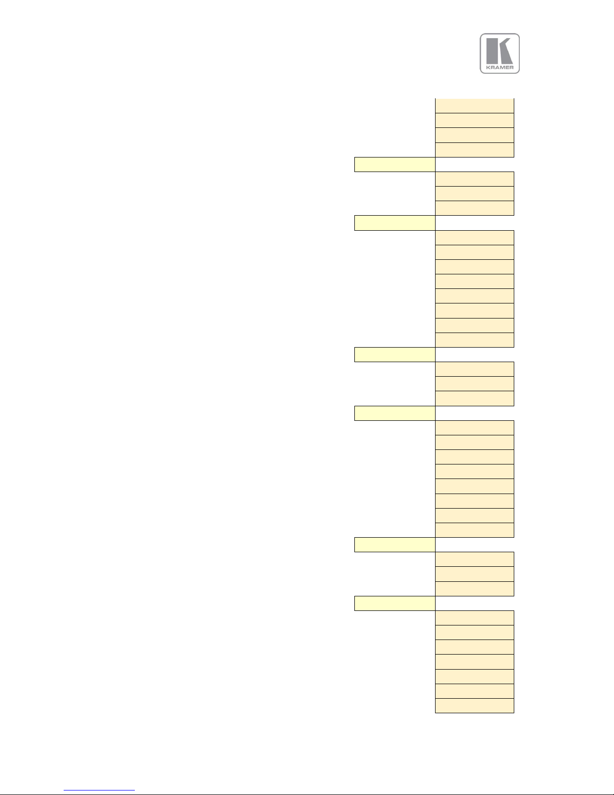
© KRAMER ELECTRONICS LTD.
Issue 1-16 May 30, 2017
82
Audio Menu
VGA
DVI
HDMI 3
HDBaseT
HDMI1 Audio
Stereo Analog
Analog with Mics
Digital
HDMI1 Analog
CVBS
Display Port
HDMI 1
HDMI 2
VGA
DVI
HDMI 3
HDBaseT
HDMI-2 Audio
Stereo Analog
Analog with Mics
Digital
HDMI-2 Analog
CVBS
Display Port
HDMI 1
HDMI 2
VGA
DVI
HDMI 3
HDBaseT
HDBT Audio
Stereo Analog
Analog with Mics
Digital
HDBT Analog
CVBS
Display Port
HDMI 1
HDMI 2
VGA
DVI
HDMI 3
Page 83
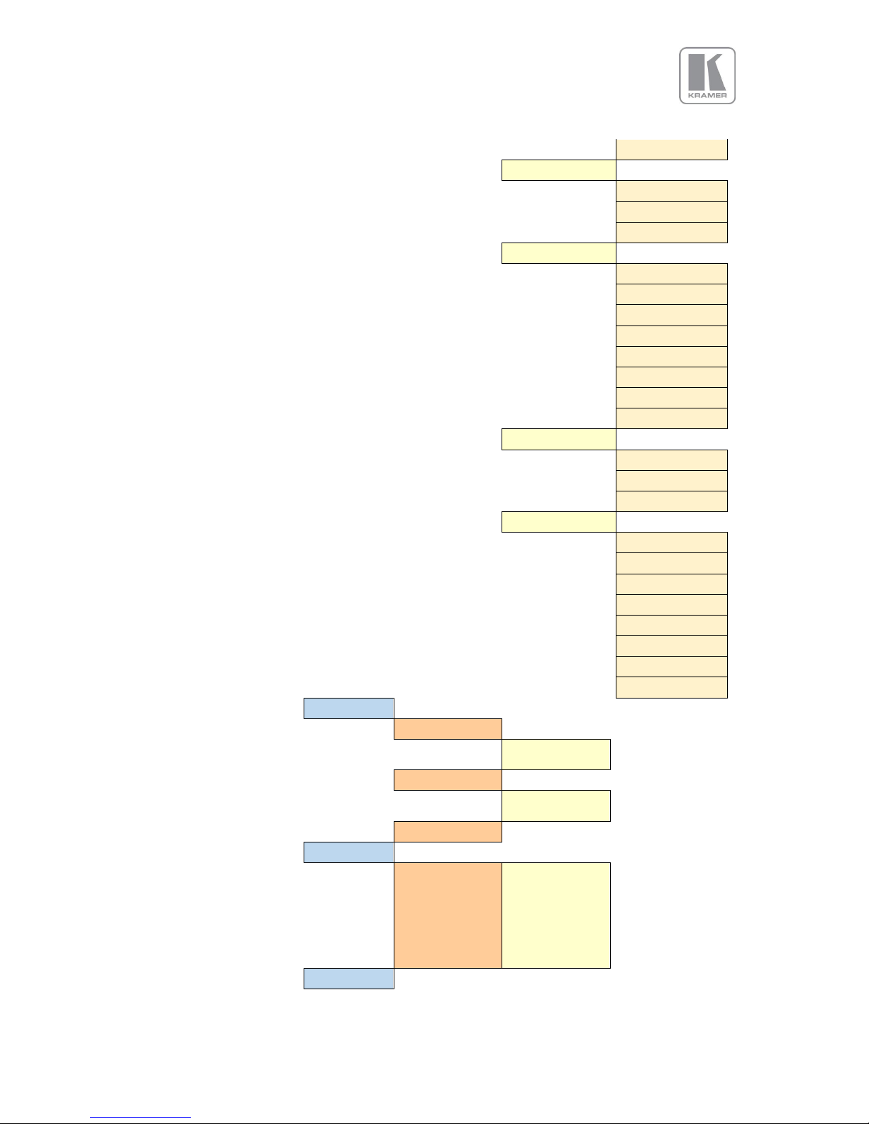
© KRAMER ELECTRONICS LTD.
Issue 1-16 May 30, 2017
83
Audio Menu
HDBaseT
HDMI-3 Audio
Stereo Analog
Analog with Mics
Digital
HDMI-3 Analog
CVBS
Display Port
HDMI 1
HDMI 2
VGA
DVI
HDMI 3
HDBaseT
DVI Audio
Stereo Analog
Analog with Mics
Digital
DVI Analog
CVBS
Display Port
HDMI 1
HDMI 2
VGA
DVI
HDMI 3
HDBaseT
Mic Config
Mic1 Phantom
Off
On
Mic2 Phantom
Off
On
Exit
Audio Out Mute
HDMI
HDBaseT
DVI/HDMI
3G-DVI
Line
Loudspeaker
Exit
On
Mute
Exit
Page 84
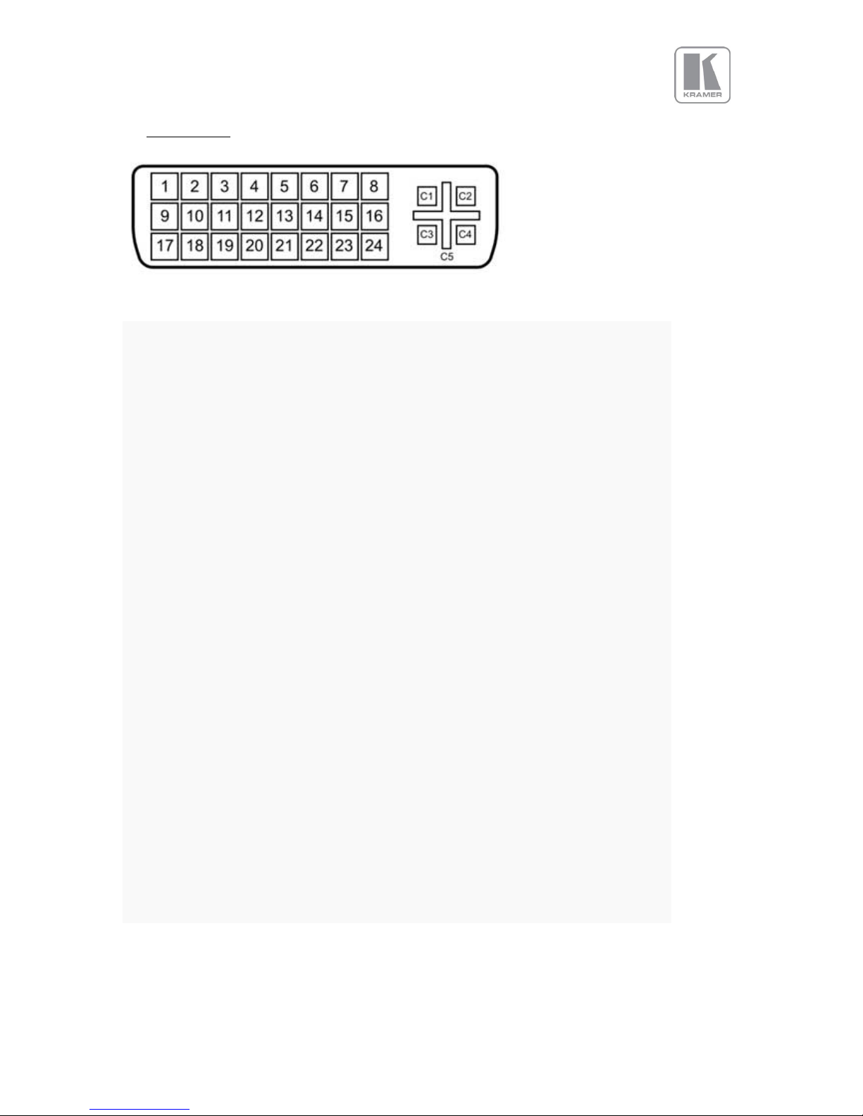
© KRAMER ELECTRONICS LTD.
Issue 1-16 May 30, 2017
84
APPENDIX C : Single Link DVI-U Pinout
Pin 1
TMDS data 2−
Digital red−
Pin 2
TMDS data 2+
Digital red+
Pin 3
TMDS data 2/4 shield
Pin 4
TMDS data 4−
Pin 5
TMDS data 4+
Pin 6
DDC clock
Pin 7
DDC data
Pin 8
Analog vertical sync
Pin 9
TMDS data 1−
Digital green−
Pin 10
TMDS data 1+
Digital green+
Pin 11
TMDS data 1/3 shield
Pin 12
Pin 13
Pin 14
+5 V
Power for monitor when in standby
Pin 15
Ground
Return for pin 14 and analog sync
Pin 16
Hot plug detect
Pin 17
TMDS data 0−
Digital blue and digital sync
Pin 18
TMDS data 0+
Digital blue+ and digital sync
Pin 19
TMDS data 0/5 shield
Pin 20
Pin 21
Pin 22
TMDS clock shield
Pin 23
TMDS clock+
Digital clock+
Pin 24
TMDS clock−
Digital clock−
C1
Analog red
C2
Analog green
C3
Analog blue
C4
Analog horizontal sync
C5
Analog ground
Return for R, G, and B signals
 Loading...