

Page 1
USER MANUAL
MODEL:
VP-772
Presentation Matrix Switcher / Dual Scaler
P/N: 2900-300295 Rev 2
www.kramerAV.com
Page 2
Page 3
Page 4

VP-772 – Contents
i
Contents
1 Introduction 1
2 Getting Started 2
2.1 Achieving the Best Performance 2
2.2 Safety Instructions 2
2.3 Recycling Kramer Products 3
3 Overview 4
3.1 HDCP Compliance for HDMI inputs 6
3.2 Defining the VP-772 Presentation Matrix Switcher / Dual Scaler 6
4 Installing in a Rack 9
5 Connecting the VP-772 10
5.1 Wiring the RJ-45 Connectors 12
5.2 Connecting the Balanced Stereo Audio Input and Outputs 13
6 The OSD Menu 14
6.1 OSD Menu Operation Example 14
6.2 The Input Menu 16
6.3 The Layout Menu 17
6.4 The Program / Preview Menus 19
6.5 The Misc Menu 22
7 The Layout 24
7.1 The Transition Mode 24
7.2 The Overlay Mode 26
8 Controlling the VP-772 29
8.1 Controlling via the Front Panel Buttons 29
8.2 Controlling via the OSD Menu 34
8.3 Controlling via the Infrared Remote Control Transmitter 39
9 Firmware Upgrade 41
9.1 The Firmware Upgrade Process 41
9.2 Rollback 43
10 Technical Specifications 44
10.1 Default Communication Parameters 45
10.2 Input Resolutions 46
10.3 Output Resolutions 47
11 The VP-772 RS-232 Communication Protocol 48
11.1 Using the Communication Protocol 48
11.2 Communication Protocol: Mimicking OSD 48
11.3 Protocol Table: Mimicking Remote and Front Panel Buttons 56
11.4 The Protocol 3000 Common Operation Commands 57
Page 5

ii
VP-772 - Contents
Figures
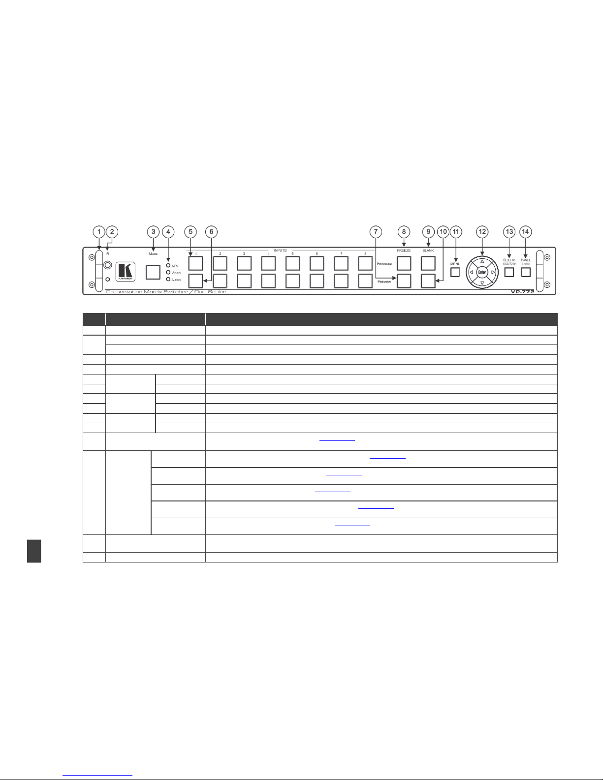
Figure 1: VP-772 Presentation Matrix Switcher / Dual Scaler Front Panel 7
Figure 2: VP-772 Presentation Matrix Switcher / Dual Scaler Rear Panel 8
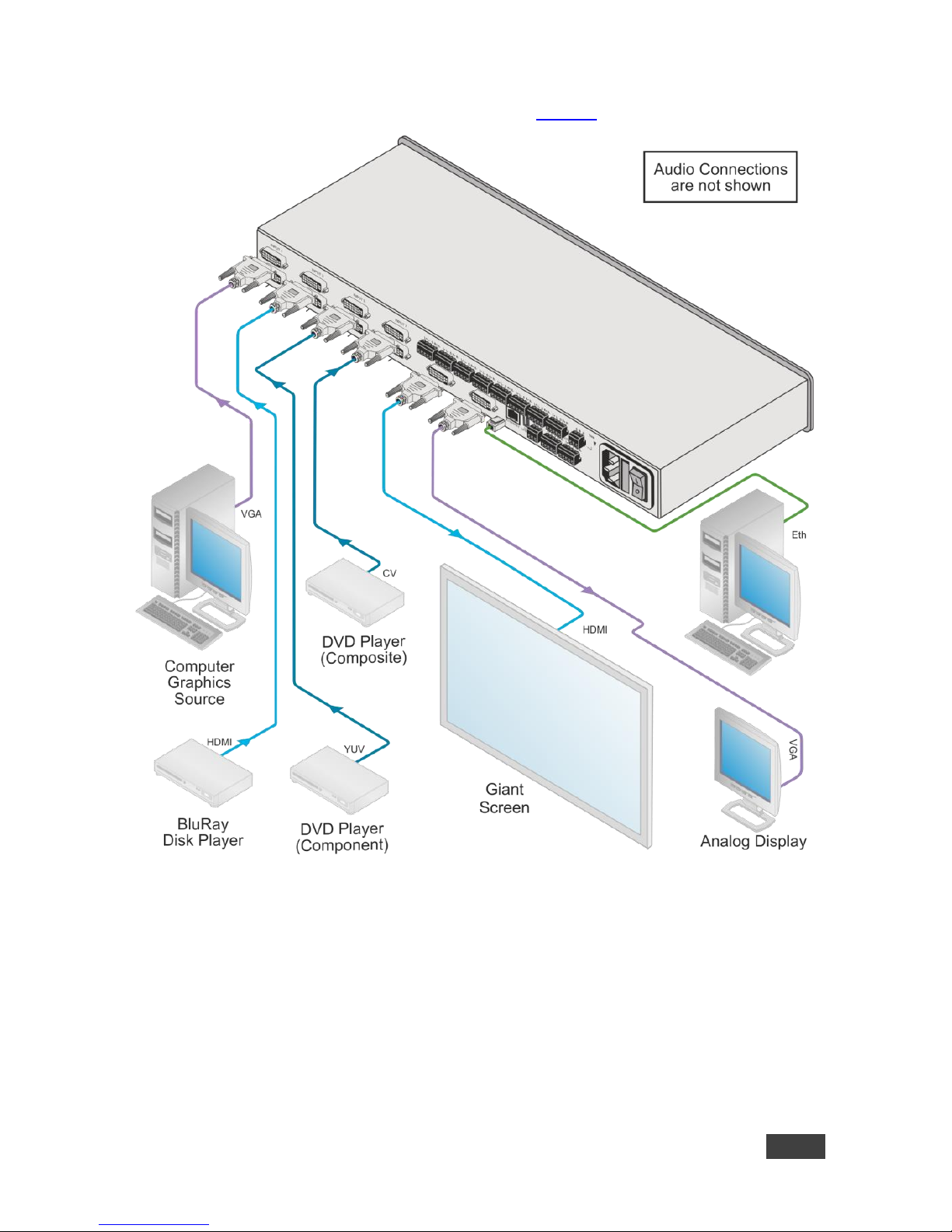
Figure 3: Connecting the VP-772 Presentation Matrix Switcher / Dual Scaler 11
Figure 4: TP PINOUT 12
Figure 5: Balanced Stereo Audio Connection 13
Figure 6: Unbalanced Stereo Audio Output Connection 13
Figure 7: Balanced Stereo Audio Input Connection 13
Figure 8: Unbalanced Stereo Audio Input Connection 13
Figure 9: OSD Menu Example 14
Figure 10: Input Menu 16
Figure 11: Layout Menu 17
Figure 12: Program/Preview Menus 19
Figure 13: Misc Menu 22
Figure 14: VGA superimposed over HDMI 27
Figure 15: RS-232 Connection 34
Figure 16: Local Area Connection Properties Window 35
Figure 17: Internet Protocol Version 4 Properties Window 36
Figure 18: Internet Protocol Version 6 Properties Window 37
Figure 19: Internet Protocol Properties Window 38
Figure 20: Infrared Remote Control Transmitter 39
Figure 21: Firmware Upgrade – list of Files to Upgrade 42
Figure 22: Firmware Upgrade – Upgrade Process 42
Figure 23: Firmware Upgrade – Upgrade Complete 42
Figure 24: Firmware Upgrade – list of Files to Rollback 43
Page 6

VP-772 – Introduction
1
1 Introduction
Welcome to Kramer Electronics! Since 1981, Kramer Electronics has been
providing a world of unique, creative, and affordable solutions to the vast range of
problems that confront video, audio, presentation, and broadcasting professionals
on a daily basis. In recent years, we have redesigned and upgraded most of our
line, making the best even better!
Our 1,000-plus different models now appear in 14 groups that are clearly defined by
function: GROUP 1: Distribution Amplifiers; GROUP 2: Switchers and Routers;
GROUP 3: Control Systems; GROUP 4: Format/Standards Converters; GROUP 5:
Range Extenders and Repeaters; GROUP 6: Specialty AV Products; GROUP 7:
Scan Converters and Scalers; GROUP 8: Cables and Connectors; GROUP 9:
Room Connectivity; GROUP 10: Accessories and Rack Adapters; GROUP 11:
Sierra Video Products; GROUP 12: Digital Signage; GROUP 13: Audio; and
GROUP 14: Collaboration.
Congratulations on purchasing your Kramer VP-772 Presentation Matrix Switcher /
Dual Scaler. This product, which incorporates HDMI™ technology, is ideal for:
Live events
Presentation applications that require a preview option
Projection systems in conference rooms, boardrooms, auditoriums, hotels
and churches, production studios, rental and staging
Any application where high quality conversion and switching of multiple and
different video signals to graphical data signals is required for projection
purposes
Presentations requiring seamless switching between inputs, using special
effects, cuts and fades
Page 7
2
VP-772 - Getting Started
2 Getting Started
We recommend that you:
Unpack the equipment carefully and save the original box and packaging
materials for possible future shipment
Review the contents of this user manual
Go to http://www.kramerav.com/downloads/VP-772 to check for up-to-date
user manuals, application programs, and to check if firmware upgrades are
available (where appropriate).
2.1 Achieving the Best Performance
To achieve the best performance:
Use only good quality connection cables (we recommend Kramer high-
performance, high-resolution cables) to avoid interference, deterioration in
signal quality due to poor matching, and elevated noise levels (often
associated with low quality cables)
Do not secure the cables in tight bundles or roll the slack into tight coils
Avoid interference from neighboring electrical appliances that may adversely
influence signal quality
Position your Kramer VP-772 away from moisture, excessive sunlight and
dust
This equipment is to be used only inside a building. It may only be
connected to other equipment that is installed inside a building.
2.2 Safety Instructions
Caution:
There are no operator serviceable parts inside the unit
Warning:
Use only the power cord that is supplied with the unit
Warning:
Do not open the unit. High voltages can cause electrical
shock! Servicing by qualified personnel only
Warning:
Disconnect the power and unplug the unit from the wall
before installing
Page 8

VP-772 – Getting Started
3
2.3 Recycling Kramer Products
The Waste Electrical and Electronic Equipment (WEEE) Directive 2002/96/EC aims
to reduce the amount of WEEE sent for disposal to landfill or incineration by
requiring it to be collected and recycled. To comply with the WEEE Directive,
Kramer Electronics has made arrangements with the European Advanced
Recycling Network (EARN) and will cover any costs of treatment, recycling and
recovery of waste Kramer Electronics branded equipment on arrival at the EARN
facility. For details of Kramer’s recycling arrangements in your particular country go
to our recycling pages at http://www.kramerelectronics.com/support/recycling/.
Page 9

4
VP-772 - Overview
3 Overview
The Kramer VP-772 is an eight input high quality dual scaler with special effect
transitions for the Rental and Staging and the Live Events market, and for other
applications where a dual scaler is needed. It features DVI-U inputs (including
analog, DVI and HDMI support) and stereo balanced audio signals. The VP-772
can also be configured as 4K single output scaler. The VP-772 scales and
processes the selected video and audio inputs, and outputs to 2 independent DVI-I
outputs (Program and Preview) together with two balanced stereo audio outputs.
The VP-772 features:
Pix Perfect™ Scaling Technology - Kramer’s extremely high performance,
State-of-the-Art scaling technology with extensive high-quality pull-down and
de-interlacing algorithms, and full up-and down-scaling of the video inputs
K-IIT XL™ Picture-in-Picture Image Insertion Technology for ultra-stable
picture−in−picture, picture−and−picture and split screen capability
Seamless video switching with cuts or built-in special effect transitions,
including horizontal, vertical, diagonal, circle, and chessboard wipes, crossfading, and more
Dual scalers—for “live” seamless transitions from one source to another—
with two independent outputs: a PREVIEW OUTPUT and a PROGRAM
OUTPUT. The PREVIEW output—including an OSD menu for making
adjustments—can be used to determine how the scaled output will look
before being displayed live during a presentation
Features 8 PREVIEW input buttons for switching a selected input to the
PREVIEW output and 8 PROGRAM input buttons for switching a selected
input to the PROGRAM output
Output Resolutions – UHD (3840x2160) resolution (in the Single Window
mode) as well as HDTV and computer graphics resolutions with selectable
refresh rates
Selectable HDMI, VGA, YUV or CV on each DVI-U input and VGA or HDMI
on each DVI-I output
Audio-Follow-Video (AFV) and breakaway options
Page 10

VP-772 – Overview
5
Advanced deinterlacing functions - including 3D comb filtering, film mode,
diagonal correction and motion detection
Multiple Aspect Ratio Selections
Built-in Proc-Amp with enhanced functions such as color correction, gamma,
dither and noise reduction
Embedded HDMI audio support as well as eight balanced stereo audio
inputs and two balanced stereo outputs
Input and output audio level adjustment and audio DSP functions
HDCP Compliance
In addition, the VP-772:
Features luma- and chroma-keying
Includes built-in test patterns for screen setup and alignment
Analyses the connected output’s EDID for optimal scaling
Provides input and output color space control
Supports HDMI deep color for outputs
Comes with an On-Screen Display (OSD) for easy setup and adjustment
Has a non-volatile memory that retains the settings
Supports firmware upgrade via USB (via memory stick)
Control your VP-772:
Directly, via the front panel push buttons
Via the Ethernet
By RS-485 (allowing future optional T-bar control)
Remotely, from the infrared remote control transmitter
By RS-232 serial commands transmitted by a touch screen system, PC, or
other serial controller
The VP-772 is housed in a 19” 1U rack mountable enclosure, with handles and rack
“ears” included, and is fed from a 100-240 VAC universal switching power supply.
Page 11

6
VP-772 - Overview
3.1 HDCP Compliance for HDMI inputs
If an HDMI signal is HDCP protected, it can only appear on HDMI
outputs that are connected to HDCP compliant displays.
The VP-772 will not output a picture on an HDMI display that is not
HDCP compliant; instead it will show a green screen.
In the PiP mode (see Section 7.2), even if only one of the inputs is HDCP
protected, and is output to a non-compliant display, it will affect the
entire screen and turn it green.
When using a VGA output display, the screen will turn black.
3.2 Defining the VP-772 Presentation Matrix Switcher / Dual
Scaler
This section defines the VP-772.
Page 12
VP-772 – Overview
7
Figure 1: VP-772 Presentation Matrix Switcher / Dual Scaler Front Panel
#
Feature
Function
1
Metal handles (x2)
Rigid handles
2
IR Receiver
Accepts IR remote commands
IR LED
Lights red when the unit accepts IR remote commands
3
MODE Button
Select the operation mode: AFV (audio follow video), Video or audio
4
Mode LED indicators
Indicate the operation mode, as selected via the MODE button
5
INPUT Selector
Buttons
PROGRAM
Press to select the DVI input (from 1 to 8) to switch to the PROGRAM output
6
PREVIEW
Press to select the DVI input (from 1 to 8) to switch to the PREVIEW output
7
FREEZE
Buttons
PREVIEW
Press to freeze/unfreeze the PREVIEW output video image
8
PROGRAM
Press to freeze/unfreeze the PROGRAM output video image
9
BLANK Buttons
PROGRAM
Press to toggle between a blank screen (black) and the PROGRAM display
10
PREVIEW
Press to toggle between a blank screen (black) and the PREVIEW display
11
MENU Button
Press to access/exit the OSD menu (see Section 8.1.1)
When browsing the Program OSD menu, a long press on the MENU button to jump to the Preview menu and vice versa
12
Navigation
Buttons
Button//
VOLUME Button
Press to move to the previous level in the OSD screen (see Section 8.1.1). When in the transition mode and not within the OSD
menu, press to decrease the Audio OUT 2 Program volume
// VOLUME
Button
Press to move up the menu list values (see Section 8.1.1) and to increase numerical values. When not within the OSD menu
mode, press to increase the Audio OUT 1 Preview volume
// VOLUME
Button
Press to move down the menu list (see Section 8.1.1) and to decrease numerical values. When not within the OSD menu mode,
press to decrease the Audio OUT 1 Preview volume
Button //
VOLUME Button
Press to move to the next level in the OSD screen (see Section 8.1.1). When in the transition mode and not within the OSD
menu, increase the Audio OUT 2 Program volume
ENTER Button
Press to enter sub-menu items, and save (see Section 8.1.1). When in the transition mode and not within the OSD menu,
performs as the TAKE button
13
RESET TO XGA/720P Button
Press to reset the video output resolution to XGA or 720p
Press and hold for about 3 seconds to toggle between reset to XGA and reset to 720p detached
14
PANEL LOCK Button
Press and hold for about 3 seconds to lock/unlock the front panel buttons
Page 13
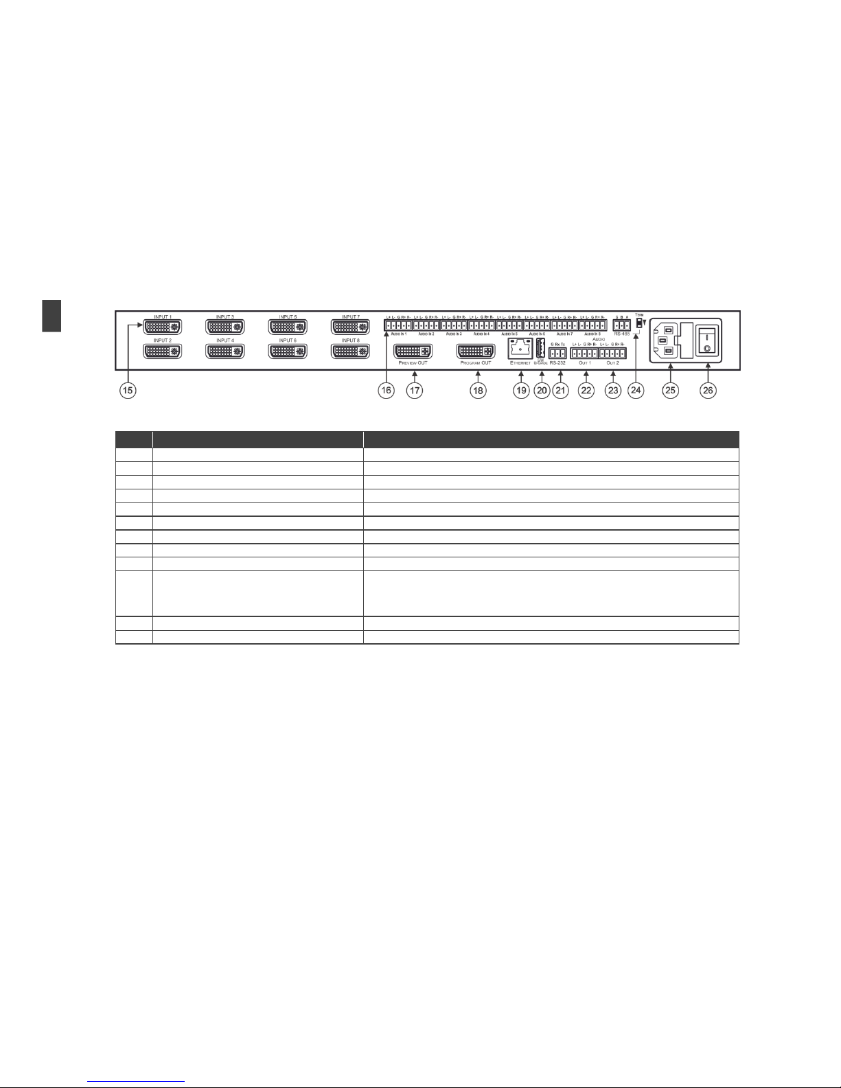
Figure 2: VP-772 Presentation Matrix Switcher / Dual Scaler Rear Panel
#
Feature
Function
15
INPUT DVI Connector
Connect to the video / embedded audio source (from 1 to 8)
16
AUDIO IN Terminal Block Connectors
Connect to the balanced stereo audio source (from 1 to 8)
17
PREVIEW OUT DVI Connector
Connect to the preview acceptor
18
PROGRAM OUT DVI Connector
Connect to the program acceptor
19
ETHERNET Connector
Connect to the PC or other Controller through computer networking
20
S/W UPGRADE USB Port
Connect to upgrade the software
21
RS-232 (G, Rx, Tx) 3-pin Terminal Block Connector
Connect to the PC or other serial controller
22
AUDIO OUT 1 terminal Block Connectors
Connect to the program balanced stereo audio acceptor
23
AUDIO OUT 2 terminal Block Connectors
Connect to the preview balanced stereo audio acceptor
24
RS-485 Port and TERM Switch
Connect to an RS-485 controller (for example, a future optional T-bar control). Pin G is for the
Ground connection; pins B (-) and A (+) are for RS-485.
Set the TERM switch down if the VP-772 is the last unit on the RS-485 line.
The ground connection is sometimes connected to the shield of the RS-485 cable.
25
Power Connector with Fuse
AC connector, enabling power supply to the unit
26
POWER Switch
Switch for turning the unit on or off
8
VP-772 – Overview
Page 14
VP-772 - Installing in a Rack
9
9
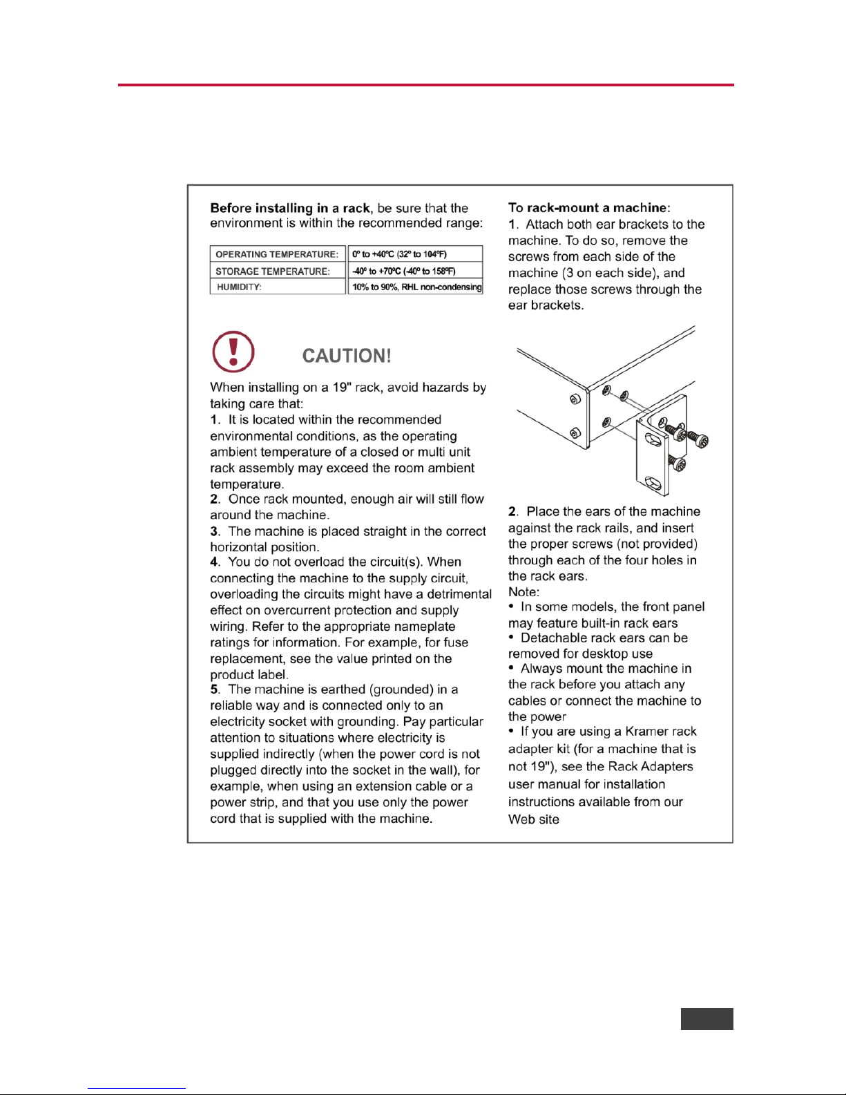
4 Installing in a Rack
This section provides instructions for rack mounting the unit.
Page 15

10
VP-772 - Connecting the VP-772
5 Connecting the VP-772
Always switch off the power to each device before connecting it to
your VP-772. After connecting your VP-772, connect its power and
then switch on the power to each device.
You do not have to connect all the inputs and outputs, connect only
those that are required.
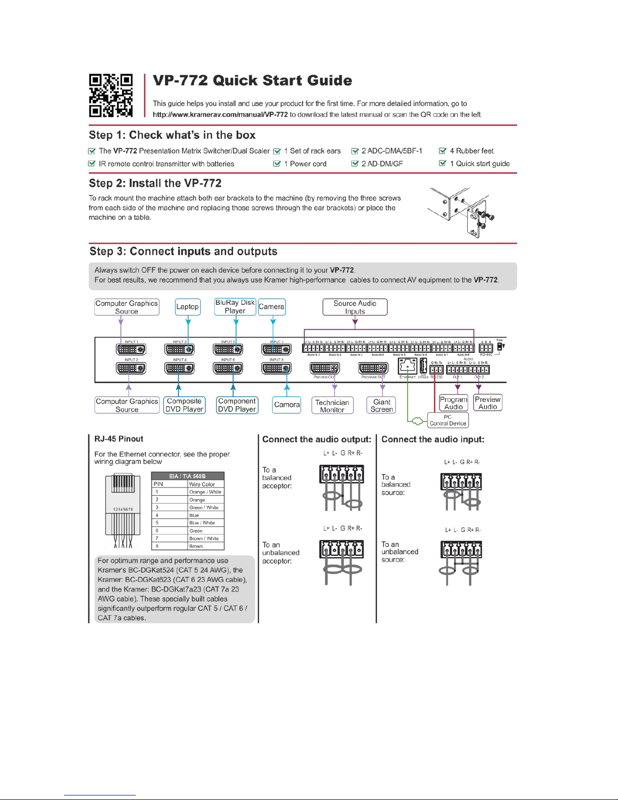
To connect the VP-772, as illustrated in the example in Figure 3, do the following:
1. Connect up to eight sources (for example, a PC, BluRay Disk Player,
Composite DVD player and so on) to the DVI INPUT connectors, according
to the Input OSD setup, see Section 6.2.
Use the ADC-DMA/5BF-1 and AD-DM/GF adapters provided with the package when
connecting a YUV, VGA or CV input, as required
2. Connect the audio input signals to the AUDIO IN terminal block connectors,
as required, see Section 5.2 (not shown in Figure 3).
3. Connect the PREVIEW OUT DVI connector to a DVI acceptor (for example,
an LCD display).
4. Connect the PROGRAM OUT DVI connector to a DVI acceptor (for
example, a projector).
Note that when high output resolutions (such as 4k2k@30) we
recommend that you use a DVI to HDMI cable (for example, the
Kramer C-HM/DM 6’ or 10’).
For lower resolutions you can connect the HDMI connector on a
device to the DVI connector on the VP-772 via a HDMI-DVI adapter
5. Connect the AUDIO OUT 1 and OUT 2 Terminal Block connectors to up to
two balanced analog audio acceptors, see Section 5.2 (not shown
in Figure 3).
6. If required, you can connect a PC and/or controller to the:
RS-232 terminal block (see Section 8.2.1)
Ethernet connector (see Section 8.2.2
Page 16
VP-772 - Connecting the VP-772
11
11
7. Connect the power cord (not shown in Figure 3).
Figure 3: Connecting the VP-772 Presentation Matrix Switcher / Dual Scaler
Page 17

12
VP-772 - Connecting the VP-772
5.1 Wiring the RJ-45 Connectors
This section defines the TP pinout, using a straight pin-to-pin cable with RJ-45
connectors.
EIA /TIA 568B
Figure 4: TP PINOUT
PIN
Wire Color
1
Orange / White
2
Orange
3
Green / White
4
Blue
5
Blue / White
6
Green
7
Brown / White
8
Brown
Page 18

VP-772 - Connecting the VP-772
13
13
5.2 Connecting the Balanced Stereo Audio Input and
Outputs
Figure 5: Balanced Stereo Audio
Connection
Figure 6: Unbalanced Stereo Audio Output
Connection
Figure 7: Balanced Stereo Audio Input
Connection
Figure 8: Unbalanced Stereo Audio Input
Connection
Page 19

14
VP-772 - The OSD Menu
6 The OSD Menu
The OSD menu lets you set the VP-772 operation parameters.
The OSD sub-menu operations appear in the OSD title, as shown in the example in
Section 6.1:
When in the main menu, the OSD title appears empty
Level 1 lists the main menu items
Level 2 includes the second hierarchy level, below level 1
Level 3 includes the third hierarchy level, below level 2
Level 4 includes the fourth hierarchy level, below level 3
Function (the fifth level), is the selectable parameter or numerical value and
can appear either under level 2, 3 or 4
6.1 OSD Menu Operation Example
In the example illustrated below, the Program Aspect Ratio is set to Best Fit as
illustrated in Figure 9 (see OSD menu in Section 6.4).
Figure 9: OSD Menu Example
The table below shows function 321 (from the Protocol in Section 11.2.2):
3 in the hundreds, represents “Program” which is the 3rd menu item in the
main list
Page 20

VP-772 - The OSD Menu
15
15
2 in the tens, represents “Scaling” which is 2nd in the Scale menu
1 in the units, represents “Aspect Ratio” which is first in the Scaling menu
Level 1
Level 2
Level 3
Level 4 (Function)
Range
Function
Program
(3)
Scaling (2)
Aspect Ratio (1)
Follow Input
0
321
Follow Output
1
Best Fit
2
Letterbox
3
Note that:
We recommend that you press Enter to save the changes to the memory
immediately although exiting the menu saves the parameter to the memory
Data is saved per window and per input (to a dedicated input + window
memory), as applicable
The control buttons let you control the VP-772 via the OSD menu. Press the:
MENU button to enter the menu and exit the menu
button when in the OSD menu, to move to the previous level and change
menu settings in the OSD screen.
ENTER (or ) button to access sub-menu items
Arrow buttons to move through the OSD menu
or arrows to change settings
Note that when exiting the menu, all the changes are automatically
saved to the non-volatile memory.
The default OSD timeout for auto exit is set to 30 seconds and can be
changed (see Section 6.5).
Note that some items appear red on the OSD menu indicating that
they are disabled.
Page 21
16
VP-772 - The OSD Menu
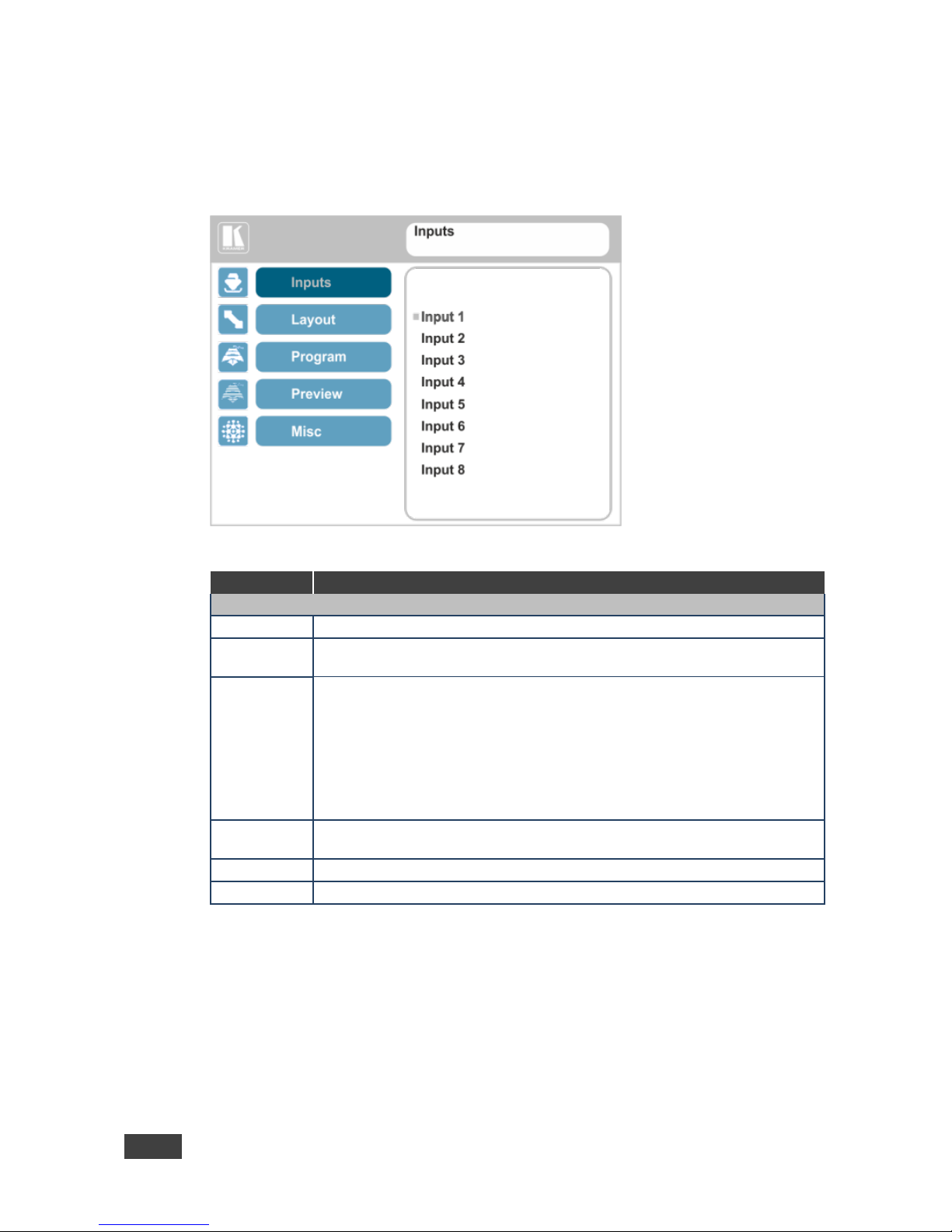
6.2 The Input Menu
The Input menu lets you set each of the VP-772 input connector parameters (from 1
to 8):
Figure 10: Input Menu
Setting
Function
INPUT 1 to INPUT 8
Type
Set the input type to HDMI, YUV, VGA or CV
EDID
Management
N/A
HDCP Mode
Set the HDCP option for each HDMI type input to either On (the default) or
Off.
Setting HDCP mode to Off on that input allows the source to transmit a nonHDCP signal if required (for example, when working with a Mac computer).
Note that if you did not get the source to transmit the desired result, make
sure you have saved the change (by pressing the ENTER button) and then
physically disconnect and reconnect the cable connecting the source to the
DVI input
Auto
Positioning
N/A
Color Space
Select the color space for each input to RGB, YPbPr or Follow Input
Volume
Set the audio level for each input
Page 22
VP-772 - The OSD Menu
17
17
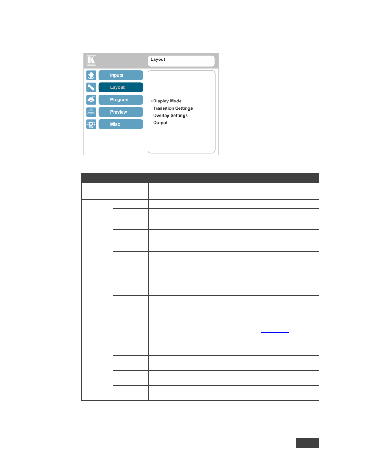
6.3 The Layout Menu
Figure 11: Layout Menu
Setting
Function
Display
Mode
Transition
Set to the Transition mode
Overlay
Set to the Picture-in-Picture mode
Transition
Settings
Speed
Set the transition speed
Mode
Set the transition mode to either Swap (program and preview
sources switch places) or Follow (the preview source follows the
program)
Effect
Select one of the following effects: Cut, Fade, Diagonal, Wipe,
Circle, Square, Diamond, Triangle, Curtain, Chessboard or
Blinds
Direction
Select the point of entry of the transition (depending on the Effect
that was selected in the previous item):
From Top Right / Left to Right / Inbound / Horizontal
From Top Left / Right to Left / Outbound / Vertical
From Bottom Right / Up / Random
From Bottom Left / Down
Take
Select to carry out the transition
Overlay
Settings
Single
Window
Set to a single window mode operation with one channel displayed
Picture in
Picture
(PiP) – dual window mode operation, a smaller window
superimposed over a full screen image (see Section 7.2)
Picture +
Picture
(PoP) – dual window mode operation, both images appear side-byside and the aspect ratios of both images are maintained (see
Section 7.2)
Split
(SbS) – dual window mode operation, both images are placed
side-by-side with the same height (see Section 7.2)
Customized
Single
N/A
Customized
Dual
N/A
Page 23
18
VP-772 - The OSD Menu
Setting
Function
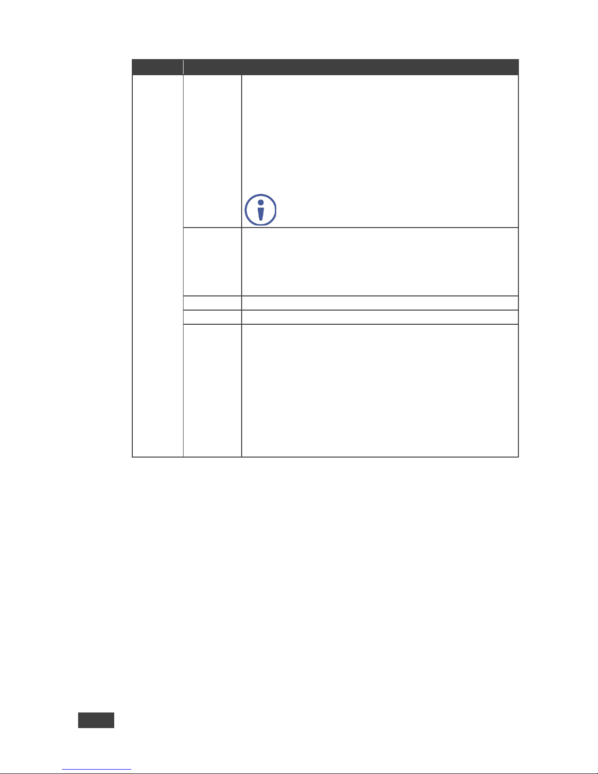
Output
Video
Resolution
Select the output resolution: Native, 640x480@60, 640x480@75,
800x600@50, 800x600@60, 800x600@75, 1024x768@50,
1024x768@60, 1024x768@75, 1280x768@50, 1280x768@60,
1280x800@60, 1280x1024@50, 1280x1024@60,
1280x1024@75, 1360x768@60, 1366x768@50, 1366x768@60,
1400x1050@50, 1400x1050@60, 1600x900@60,
1600x1200@50, 1600x1200@60, 1680x1050@60,
1920x1200@60RB, 480p60, 576p50, 720p50, 720p59.94, 720p60,
1080p23.976, 1080p24, 1080p25, 1080p29.97, 1080p30,
1080p50, 1080p59.94, 1080p60, 1080i50, 1080i60, 2k50, 2k60,
4k2k30
Note that setting the output resolution to 4k2k30 will
automatically change the window settings to Single
Window in the Overlay mode.
Master
Connection
Set to Program or Preview to determine the Machine’s behavior.
If the native resolution is not supported by the selected Master
Connection, the system searches for the best supported resolution. If
the search fails (for example, if the master connection is disconnected
or EDID is unreadable), the resolution will default to XGA.
Deep Color
N/A Color Space
Select RGB, YPbPr422 or YPbPr444
HDCP Mode
Define the output HDCP activation policy. Set to:
Follow Output (this option is recommended when the HDMI type
output is connected to a splitter/switcher) – to activate the HDCP
per output according to the setting of the HDMI acceptor to which it
is connected; that is, if the HDMI acceptor is not HDCP compliant,
the VP-772 always outputs without HDCP and vice versa.
Follow Input – to activate the HDCP on all HDMI type outputs in
the case that the video on the Main or PiP window is HDCP
encrypted.
Note that the VP-772 will output a green screen if the output
acceptor to which it is connected is not HDCP compliant, in the
case that the video on the Main or PiP window is HDCP encrypted.
Page 24
VP-772 - The OSD Menu
19
19
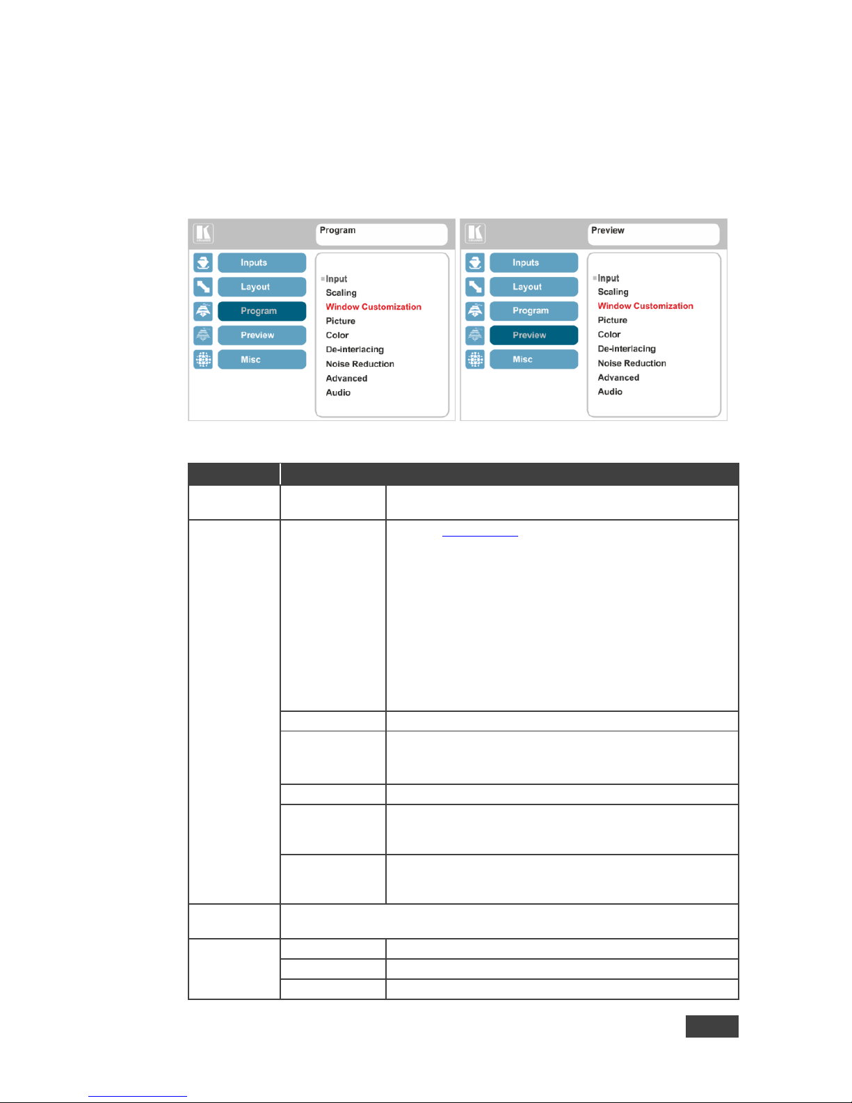
6.4 The Program / Preview Menus
The Program and Preview menus are identical.
Note that when browsing the Program OSD menu, use a long press on the MENU
button to jump to the Preview menu and vice versa.
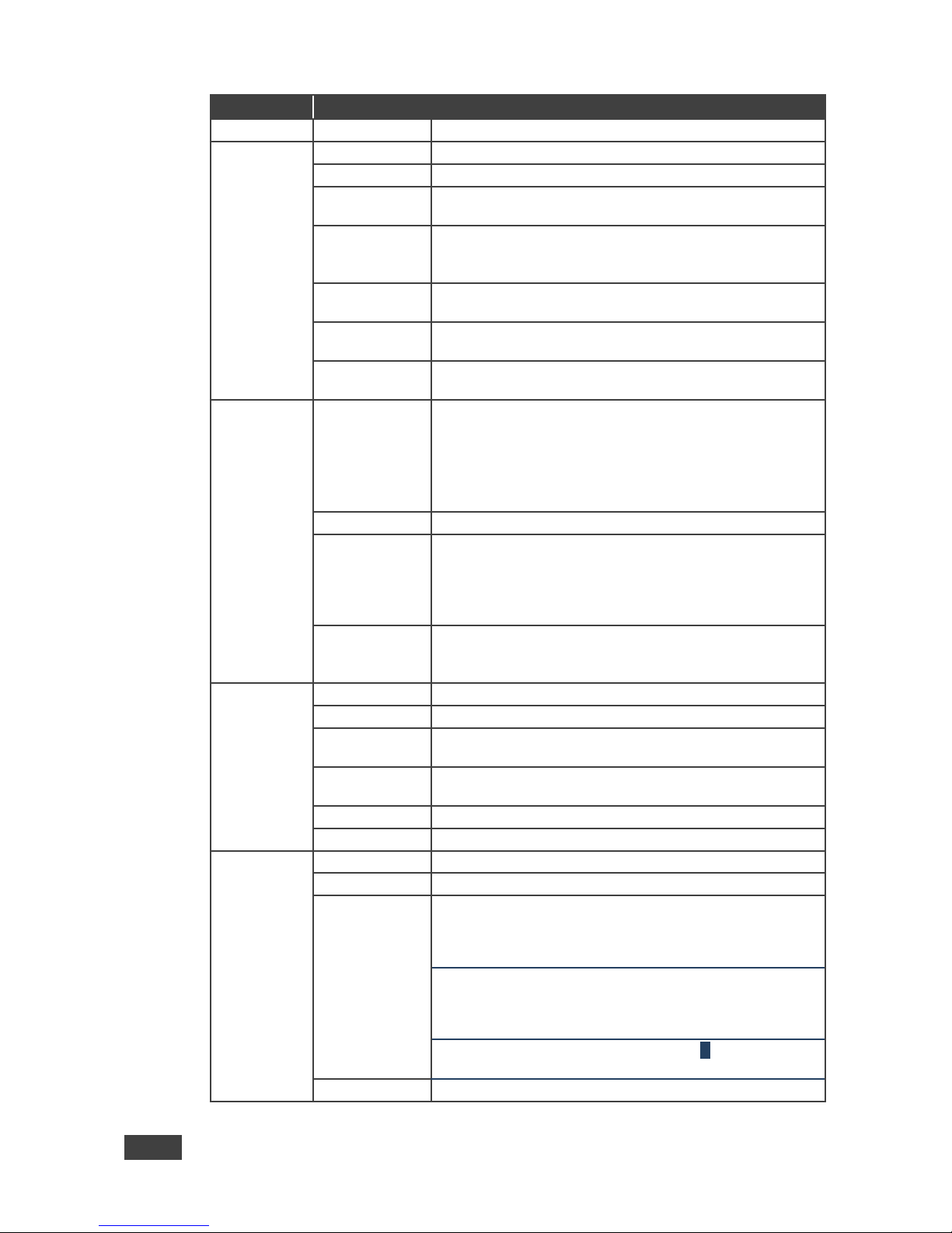
Figure 12: Program/Preview Menus
Setting
Function
Input
Input 1 to Input
8
Select the Program/Preview source and then set the
parameters below (which are specific per input)
Scaling
Aspect Ratio
Set (see Section 6.4.1) to:
Follow Input – If the input resolution ≤ output resolution,
display with a blank border.
input > output is denied and the aspect ratio automatically
changes to Follow Output
Follow Output – If the input resolution < output resolution,
scale up the picture. If the input resolution > output
resolution, scale down the picture
Best Fit – the best possible compromise between the input
and the output aspect ratios
Letterbox – to compress the top and bottom edges of the
input signal, but fill the width of the screen
Overscan
Set the Overscan to Follow Input, Off, 5% or 10%
Ratio Shift Mode
Set to:
Auto – to fit the image to the display
Customized – N/A
Ratio
N/A
H image Shift
Set the horizontal position of the image within the window
(note that this is a volatile parameter when selecting Ratio
Shift Mode > Auto)
V image Shift
Set the vertical position of the image within the window
(note that this is a volatile parameter when selecting Ratio
Shift Mode > Auto)
Window
Customization
N/A
Picture
Brightness
Set the brightness level
Contrast
Set the contrast level
H Sharpness
Select the horizontal sharpness level
Page 25
20
VP-772 - The OSD Menu
Setting
Function
Picture
V Sharpness
Select the vertical sharpness level
Color
Chroma
Set the color level
Hue
Set the color hue
Color
Temperature
Set the color temperature to 6500K or 9300K
Gamma Mode
Set the gamma correction factor to Off, 0.4, 0.8, 1.2, 1.6,
2.0, 2.4 or 2.8
The higher the value, the darker the image
Color Correction
Blue
Set the blue color level from 0 to 4
Color Correction
Green
Set the green color level from 0 to 4
Color Correction
Flesh
Set the flesh color level from 0 to 4
De-interlacing
Film Mode
Set to:
Off – for no pull-down
Follow Input – to automatically identify the required pull-
down (2:2, 2:3, 2:3:3:2, 2:3:3:2:2, 2:3:2:3:2, 5:5 or 8:7 pulldown)
24PsF – to force 24PsF pull-down
PD Time
Set the pull down time
Motion
Detection
Sensitivity
Set (from Level 1 to Level 5)
Select the motion detection sensitivity for filtering of
interlaced images. Set a high value for video where there is
generally a large amount of motion, or a low value for little
motion
Diagonal
Correction
Set the level of diagonal interpolation from 0 to 3.
When set to the lower level, the diagonal image does not
appear smooth
Noise
Reduction
Horizontal NR
Reduces the horizontal noise
Vertical NR
Reduces the vertical noise
Temporal NR
The higher the level, the stronger the filtering of the image.
Useful when the noise is visible to the eye
Block NR
As the level is set higher, the block noise disappears and
the image appears softer
Mosquito NR
The higher the level, the stronger the filtering of the image
Combing NR
Improves the quality of the subtitles
Advanced
Geometry
N/A V-Keystone
N/A
Pause
Set Freeze to On to freeze the window (freezing the
window will also mute the audio output)
Any change in the input source may cancel the freeze and blank
settings
Set Blank to On to display a blank window (blanking the
window will also mute the audio output)
Any change in the input source may cancel the freeze and blank
settings
Set Mute to On to mute the audio output E
A mute icon appears on screen
Power Save
N/A
Page 26
VP-772 - The OSD Menu
21
21
Setting
Function
Advanced
(continued)
Test Pattern
Set the Test pattern to Slide Bar (non-HDCP), Color Bar
(HDCP) or Off.
Each test pattern includes a sinusoid audio signal at 10dB
@1kHz.
We recommend that you set the Display Mode to Single
Window and set the Output Resolution to 1080p.
No Signal
If there is no signal on the input set the output color to
Gray, Blue or Black
Auto Switching
N/A
Audio
Source
Select the audio source to be:
AFV for the audio to follow the video
Analog 1 to Analog 8 to select any of the analog audio
inputs
AFV Source
When in the AFV mode, select Embedded for the
embedded audio source to follow the video
Select Analog for the analog audio source to follow the
video
Output Volume
Set the output volume level
Bass
Set the bass level [dB]
Mid
Adjust the midrange frequency
Treble
Adjust the treble
Balance
Adjust the balance
Lip sync
Set the Lip Sync delay value [msec]
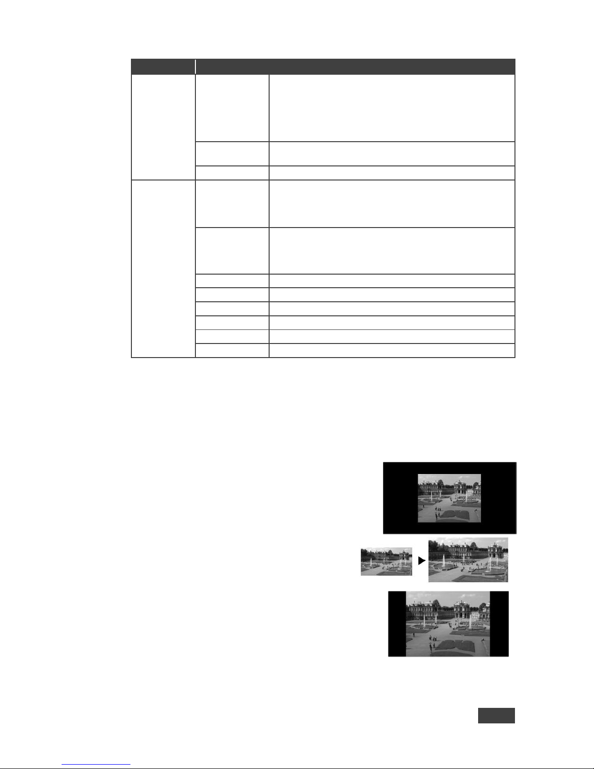
6.4.1 Selecting the Correct Aspect Ratio
You can configure the aspect ratio of any output image to fit your application. The
VP-772 offers four different aspect ratio settings: Follow Input, Follow Output, Best
Fit and Letterbox. Here is how each of these settings works.
FOLLOW INPUT – The aspect ratio and resolution of the
input video or graphics signal are both preserved (no
scaling). For example, a composite video image with a 4:3
aspect ratio will appear with the same aspect ratio on a
1080p (16:9) output image, surrounded by black bars
FOLLOW OUTPUT – The aspect ratio and resolution
of the input signal is re-sized to precisely match the
aspect ratio and resolution of the VP-772 output
signal. This may result in some distortion to the input
signal images
BEST FIT – This setting re-sizes the video or
graphics input signal to “best fit” the output resolution
while maintaining the aspect ratio of the input signal.
For example, a composite video signal (4:3 aspect
ratio) will “best fit” to the top and bottom of a
widescreen output image, resulting in black pillars on
either side.
Page 27
22
VP-772 - The OSD Menu
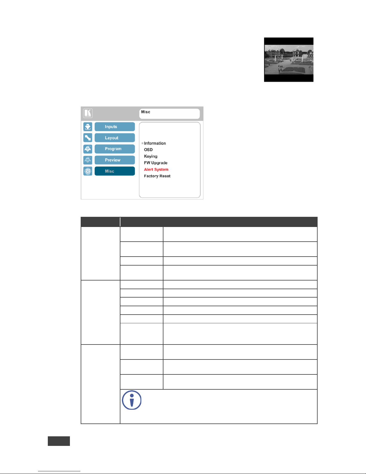
LETTERBOX – This setting compresses the top and
bottom edges of the input signal, but fills the width of
the screen. For example, to preserve a widescreen
film image on a 4:3 display. When not using a 4:3
resolution, this mode is identical to Best Fit
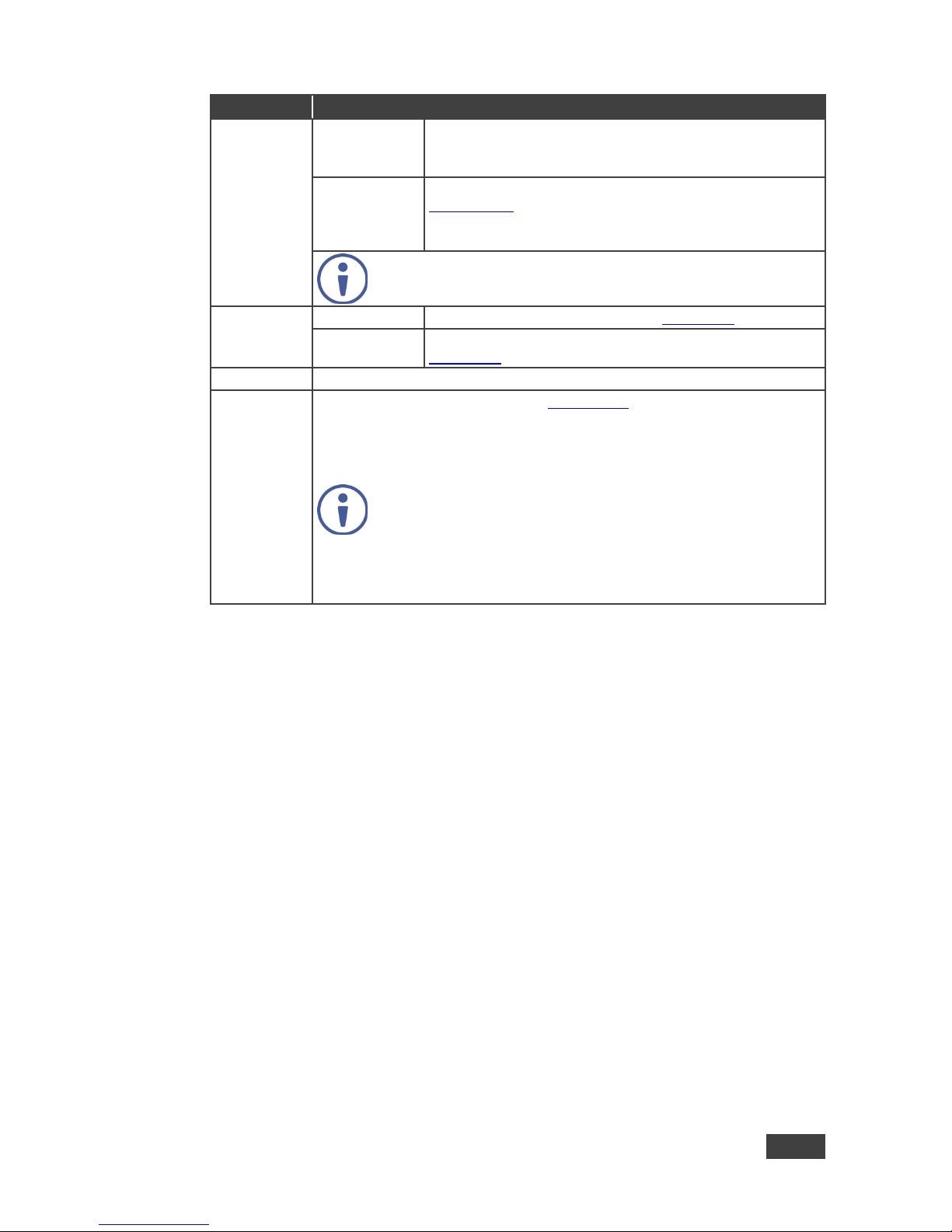
6.5 The Misc Menu
Figure 13: Misc Menu
Setting
Function
Information
Program
Displays the Program settings: selected input, input
resolution, frequency and output resolution
Preview
Displays the Program settings: selected input, input
resolution, frequency and output resolution
FW Versions
Shows the different FW versions
Network
Displays the network information: IP address, Netmask,
Gateway and DHCP
OSD
H Position
Set the horizontal position of the OSD
V Position
Set the vertical position of the OSD
Transparent
Set the transparency to On or Off
Gain
Set the transparency level (once set to transparent)
Bias
Set the transparency level
Timeout
Set to 30 seconds before OSD timeout, 60 seconds before
OSD timeout or Off (Off means that that the OSD appears
continuously)
Keying
Chroma Keying
Red
Set the threshold value of the red components for chroma
keying
Chroma Keying
Green
Set the threshold value of the green components for chroma
keying
Chroma Keying
Blue
Set the threshold value of the blue components for chroma
keying
Note that the combination of threshold values (for red, green
and blue) determines the chroma keying threshold. Any image
with combined values of red, green and blue that are below
this threshold will become transparent when chroma keying is
enabled (see below).
Page 28
VP-772 - The OSD Menu
23
23
Setting
Function
Keying
(continued)
Chroma Keying
Set to On or Off to enable/disable chroma keying
Note that this feature is available in overlay mode dual
windows
Luma Keying
To turn the keying on the PiP window On or Off (see
Section 6.5.1)
Note that this feature is available in overlay mode dual
windows
Note that either chroma keying or luma keying can be enabled.
If one is set to On , the other will be Off.
FW upgrade
Upgrade
Select to upgrade the firmware (see Section 9.1)
Rollback
Select to return to the previous firmware revision (see
Section 9.2)
Alert System
N/A
Factory Reset
Reset to factory default values (see Section 10.1).
Select Including ETH to perform a full factory reset or Excluding ETH to
reset without ETH parameters.
Once Factory Reset is selected, a countdown appears, letting you cancel the
process and revert to the previous state
DO NOT turn the machine off during the factory reset
process.
The factory reset process takes up to 3 minutes in which all
the front panel button lights turn off (except for the PANEL
LOCK button) and then turn on again; the image on the
displays reappears and only then you can turn the machine
off if required
6.5.1 The Luma Keying Feature
The luma keying feature lets you display the Preview window (the key image) as
semi-transparent over the Program window. This feature can be used to have the
Preview window display a static or dynamic logo, for example, which will appear on
a transparent background.
To apply the luma keying feature, first set the Preview window to the desired size
and location and then turn luma keying On. The Preview image will show without its
background.
The lower the luminance in the Preview window, the more transparent it becomes,
thus letting the Program window image show. The higher the luminance, the less
transparent it becomes, not letting the Program window show through. To use this
feature it is recommended to set the Preview image as follows: use low-luminance
colors for the background (the key image portion) and high-luminance colors for the
logo.
Page 29

24
VP-772 - The Layout
7 The Layout
The VP-772 can function in two modes, the:
Transition mode
Overlay (Picture in Picture) mode
The operation modes are set by selecting the display Mode via the Layout menu
(see Section 6.3).
7.1 The Transition Mode
In the transition mode you can setup the input, view it via the preview output and
then switch it to the PROGRAM output.
The VP-772 has two outputs: a PREVIEW output, and a PROGRAM output. Each
of these outputs functions independently. An input is routed to the PROGRAM
OUTPUT by pressing that PROGRAM INPUT front panel button. In the same way
pressing a PREVIEW INPUT front panel button will route that input to the
PREVIEW OUTPUT.
Use the PREVIEW output to:
See how the scaled output looks before displaying live during a presentation
Harmonize the transition to the PROGRAM output after determining the look
and feel when in the PREVIEW output
Use the OSD menu to make adjustments and choose the settings
When in the transition mode, you can set the speed of the transition, and determine
the type and direction of the transition via the OSD menu (see, Section 6.3).
For example, select Cut for an instantaneous transition from the PREVIEW output
to the PROGRAM output or select Chessboard for a chessboard transition effect
and check Swap to interchange the preview with the program.
To switch the inputs in the transition mode via the OSD menu, you need to set the
audio signal, define the effects and select the input:
Page 30

VP-772 - The Layout
25
25
1. In the Preview>Advanced>Audio menu, set the Audio signal:
Set either AFV for the audio to follow the video, or an analog input from 1
to 8
If AFV was selected, set that audio signal to be embedded or analog
Set the output volume, bass, mid, treble, balance and lip sync
2. In the Layout menu, set the display mode (for example, Transition).
3. Define the transition settings: Speed, Mode, Effect and Direction.
4. In the Preview menu, select an Input.
5. In the Layout menu select Take to carry out the transition.
To switch the inputs in the transition mode via the front panel buttons:
1. In the Preview>Advanced>Audio menu, set the Audio signal:
Set either AFV for the audio to follow the video, or an analog input from 1
to 8
If AFV was selected, set that audio signal to be embedded or analog
Set the output volume, bass, mid, treble, balance and lip sync
2. In the Layout menu, set the display mode (for example, Transition).
3. Define the transition settings: Speed, Mode, Effect and Direction.
4. Press the desired PREVIEW INPUT front panel button.
5. Press ENTER to carry out the transition.
To set the Program input, repeat the above procedures using the Program menu
If the transition mode is set to Swap, the Preview and Program inputs switch
places. If Follow was selected, the Program input setting will follow the Preview
setting and both will display the same input.
Page 31
26
VP-772 - The Layout
7.2 The Overlay Mode
In the Overlay mode both outputs are identical and can display a single image
(single window display mode), two images one over the other or two images side by
side (dual window display mode).
A selected Program input appears as the main image in a dual window display
mode (such as PiP) or as the only image in a single window display mode.
A selected Preview input will appear as the PiP window in the dual window display
mode and will not appear at all in the single window display mode.
The overlay settings item in the Layout menu (see Section 6.3) lets you set a Single
Window, Picture in Picture (PiP), Picture + Picture (PoP) or Split images. For
example, you can show a live video window on top of a graphic background, or
show two images on screen of the same input channel. The PiP window appears
even if no input signals are connected. In this case the PiP window appears in dark
gray and the main window appears in light gray.
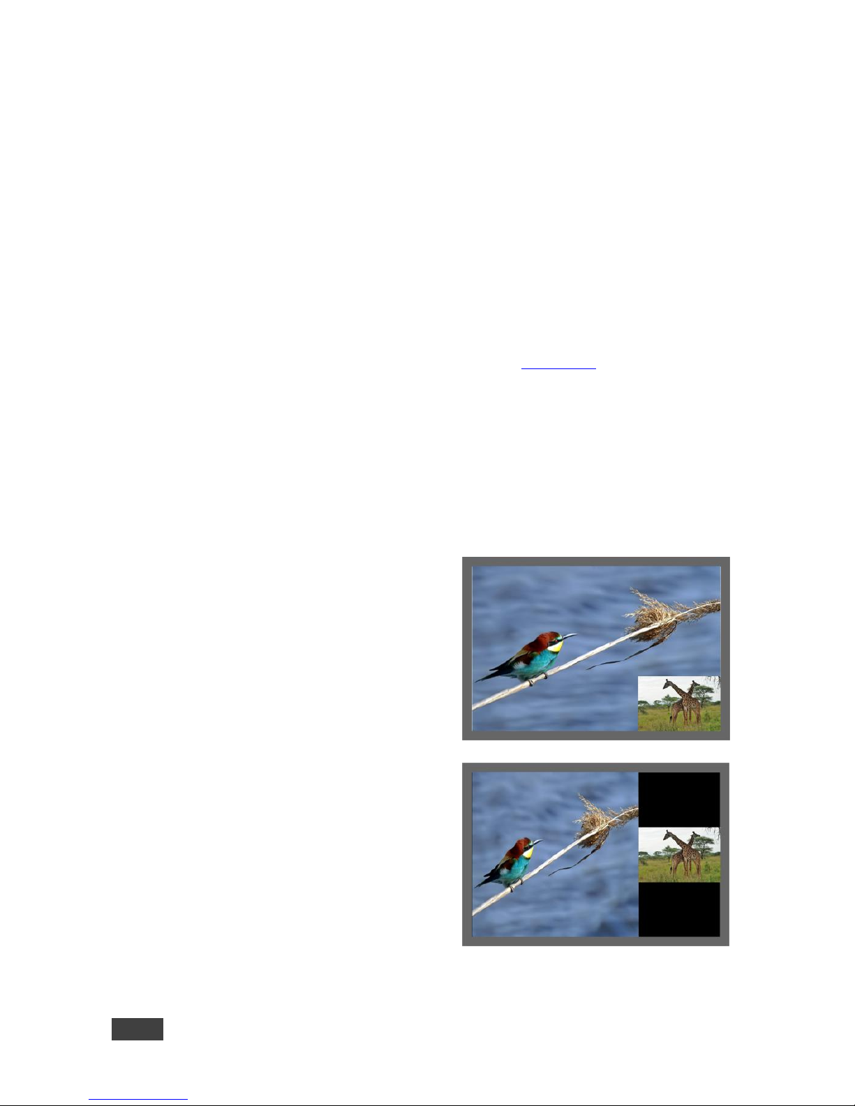
The preset PiP configurations are available:
Picture-in-Picture, with a smaller PiP
window superimposed over a full main
window image
Picture + Picture, where both images
appear side-by-side and the aspect
ratios of both images are maintained
Page 32
VP-772 - The Layout
27
27
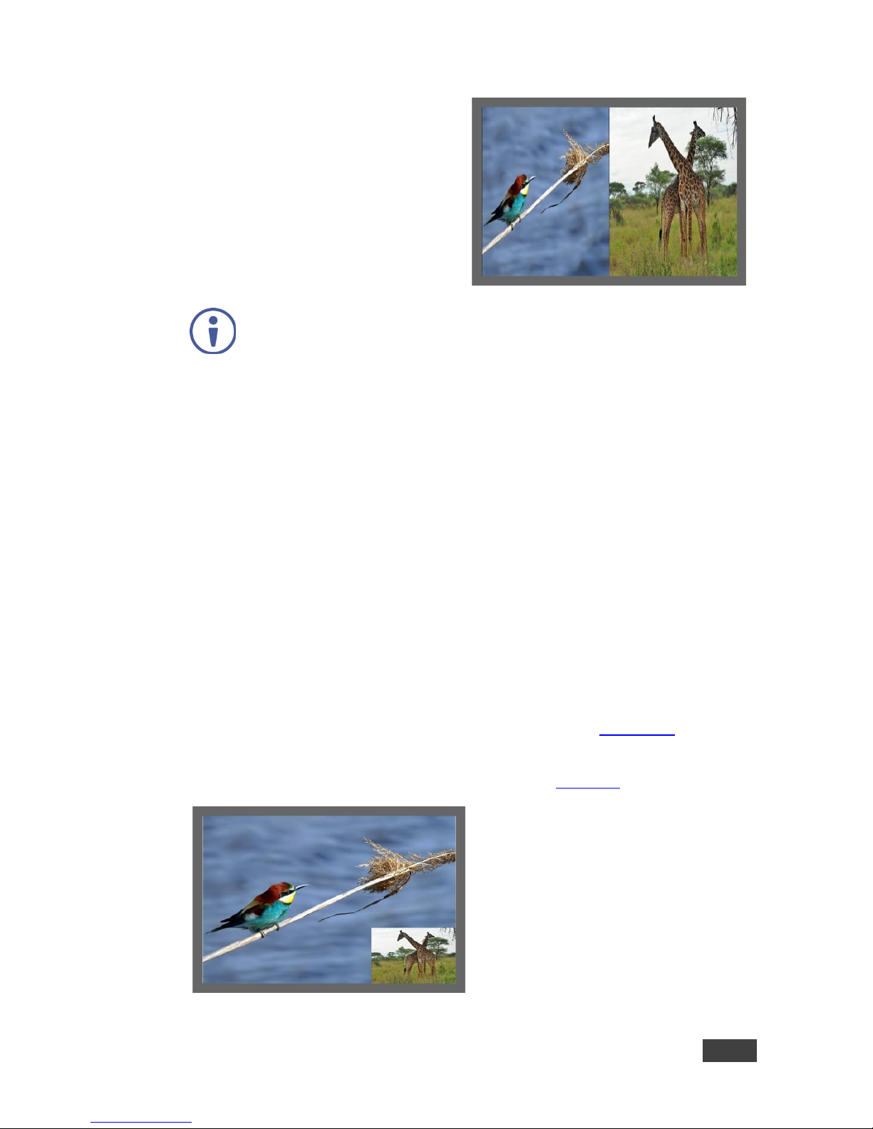
Split, where both images are placed
side-by-side with the same height
You can superimpose any input type over any or the same input.
If the HDMI signal is HDCP protected, it can appear on HDMI and
HDBT outputs that are connected to supported HDCP compliant
displays. However, it cannot appear on a display that is not HDCP
compliant and will show a green screen instead.
7.2.1 Setting the PiP
To set the PiP window in the Overlay mode:
1. In the Layout menu select Overlay Settings.
When in the Overlay display mode
2. Select the type of image you want displayed: Picture in Picture, Picture +
Picture, Split or Single Window.
7.2.1.1 Selecting the PiP Source via the Front Panel Buttons
When in the Overlay mode (set only via the OSD menu, see Section 6.3), select the
main window by pressing a Program input front panel button and select the PiP
window by pressing a Preview front panel button (see Figure 14).
Figure 14: VGA superimposed over HDMI
Page 33

28
VP-772 - The Layout
7.2.1.2 Selecting the PiP Source via the IR Remote Control
Transmitter
Press a Program button (from 1 to 8) to select the main window and press ENTER.
Press a Preview button (from 1 to 8) to select the PiP window (see Section 8.3).
7.2.1.3 Selecting the Program/Preview Source via the OSD
Menu
You can select an input source only after you set the Display mode to
the Overlay mode (see Section 6.3).
To set the Program/Preview source via the OSD menu, do the following:
1. Press the MENU button to access the OSD menu.
2. In the Layout menu set Display Mode to Overlay.
3. In Overlay Settings set the image display to any of the dual window options
or to single window.
4. In the Program/Preview menu, select Source.
5. Select an input (from 1 to 8).
6. Press the ENTER button.
7. Press the MENU a few times until you exit the OSD menu (changes are
saved upon exit).
Page 34

VP-772 - Controlling the VP-772
29
29
8 Controlling the VP-772
The VP-772 can be controlled via:
The front panel buttons (see Section 8.1)
The OSD menu (see Section 8.2)
The infrared remote control transmitter (see Section 8.3)
8.1 Controlling via the Front Panel Buttons
The VP-772 includes the following front panel buttons:
Mode button to select AFV, Video or Audio switching (see Section 8.1.1)
Program and Preview input selector buttons (see Section 8.1.1)
FREEZE and BLANK buttons (note, these buttons illuminate green when
selected)
MENU and ENTER buttons, up, down, left and right arrow buttons to
navigate through the OSD menu (see Section 6)
Enter button functions as TAKE when in the transition mode to carry out a
transition
Program output volume up () and down () buttons (when not in the OSD
mode)
Preview output volume up () and down () buttons (when not in the OSD
mode)
RESET TO XGA/720p and PANEL LOCK buttons
Page 35
30
VP-772 - Controlling the VP-772
8.1.1 Using the Mode Buttons
Press the MODE button to toggle between the AFV (green LED) mode, the VIDEO
(orange LED) mode and the Audio (red LED) mode. When selected, each mode
defines the function of the Program and Preview front panel buttons when next
pressing the front panel buttons. That is, when in the:
AFV mode, press an INPUT button to select the video together with its audio
signal
VIDEO mode, to select the video inputs only
AUDIO mode to select the audio inputs only
Note that the MODE button indicates the status for the next press on
the front panel input buttons only.
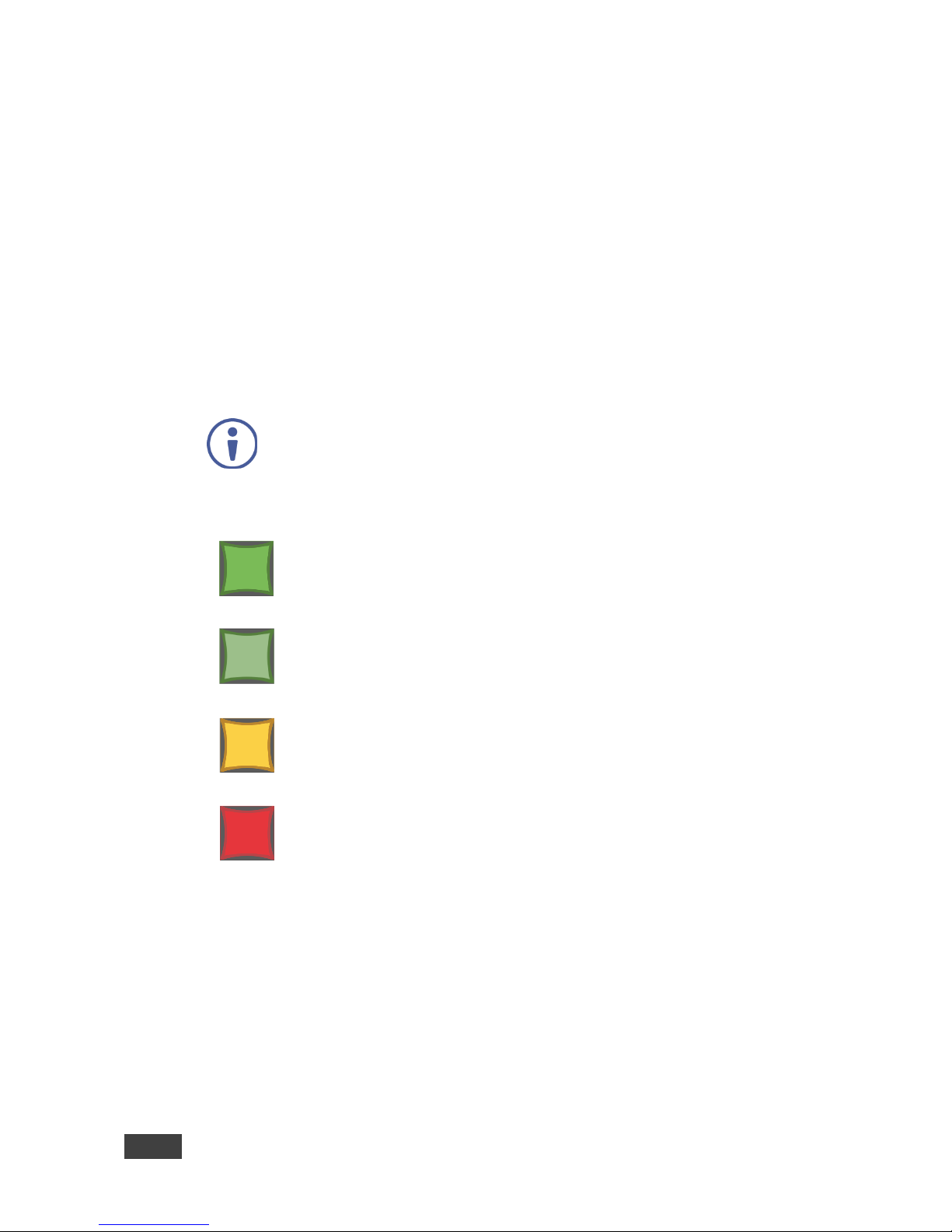
The input buttons light in accordance with the selected modes:
A bright green button indicates that both the audio and video signals
of that input are selected (AFV with embedded audio signal)
A medium green button indicates that both the audio and video
signals of that input are selected (AFV with analog audio signal)
An orange button indicates that only the video signal of that input is
selected
A red button indicates that only the audio signal of that input is
selected
Page 36
VP-772 - Controlling the VP-772
31
31
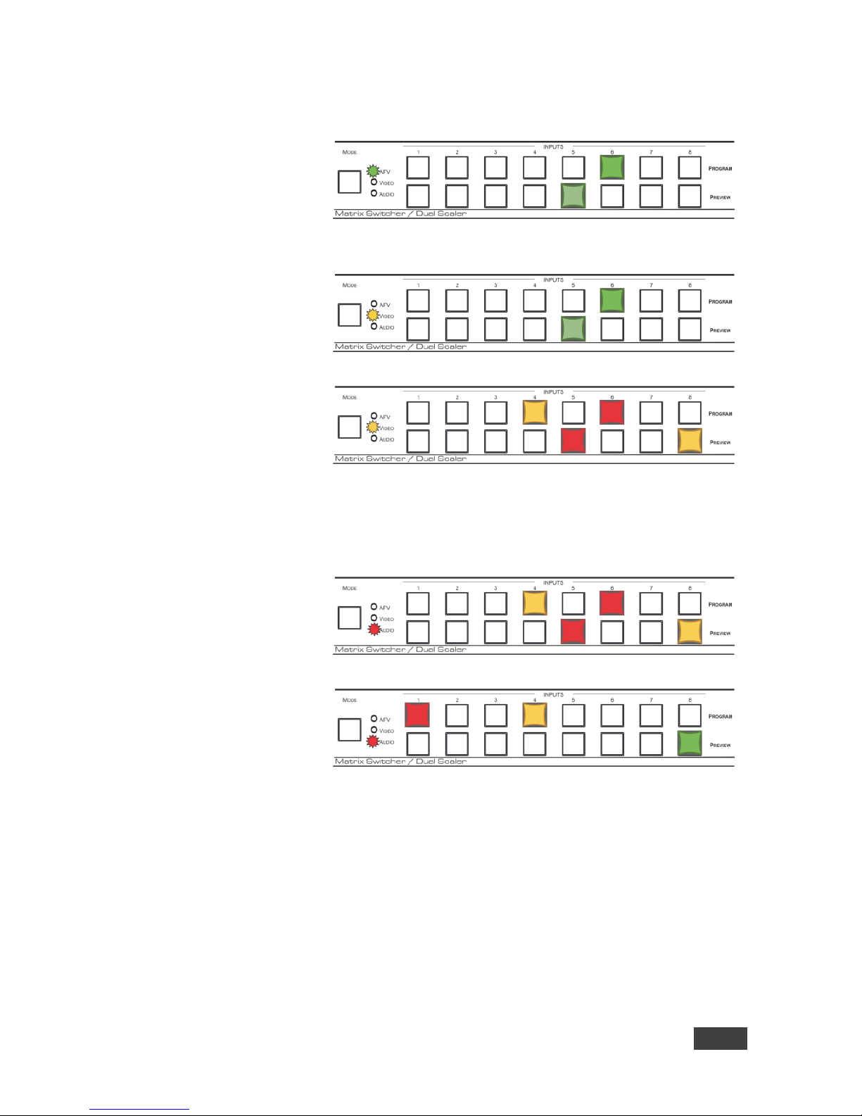
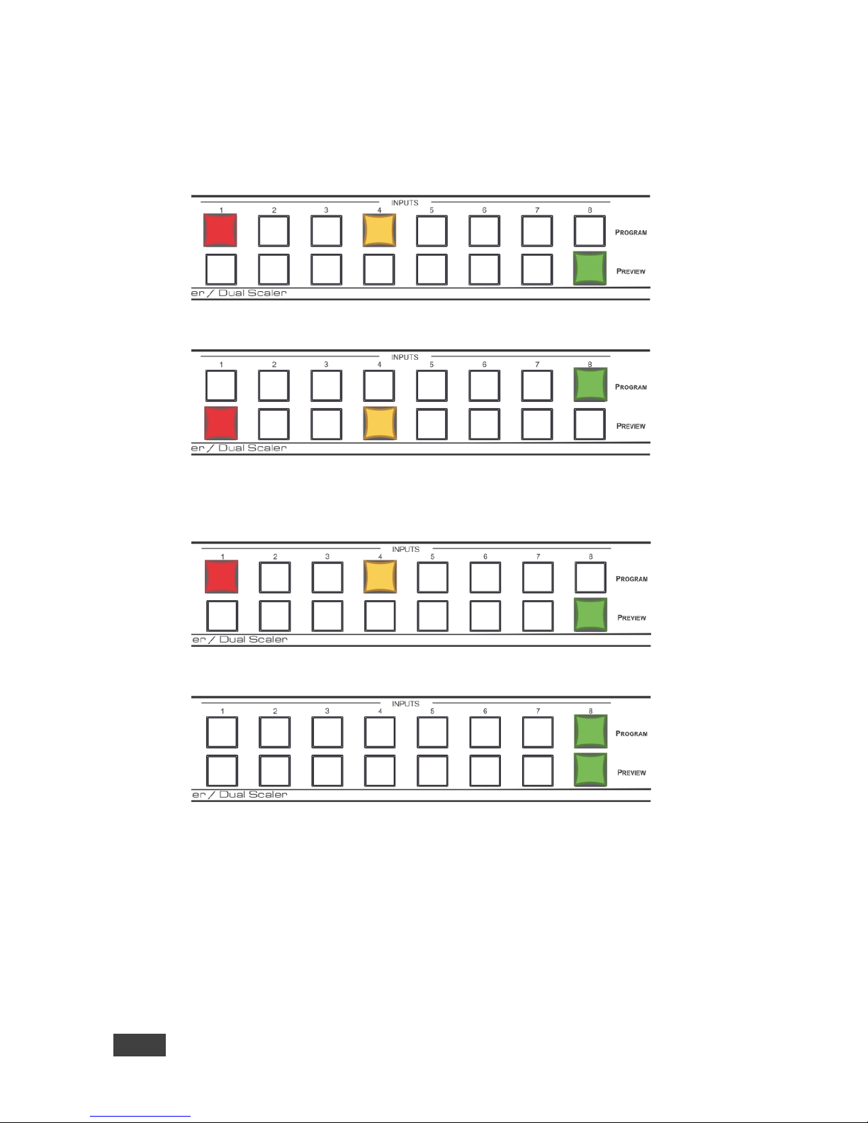
The following example shows how to use the front panel buttons to switch inputs:
Program INPUT 6
and Preview INPUT
5 are selected.
The AFV mode is
selected (Programembedded audio
signal; Preview
analog audio signal).
Press the MODE
button to set it to the
VIDEO mode.
This will affect the
next press of input
buttons
Press Program
INPUT 4 – the video
only switches to
INPUT 4 and the
audio remains in
INPUT 6.
Press Preview
INPUT 8 – the video
only switches to
INPUT 8 and the
audio remains in
INPUT 5
Press the MODE
button to set it to the
AUDIO mode.
This will affect the
next press of input
buttons
Press Program
INPUT 1 – the audio
only switches to
INPUT 1 and the
video remains in
INPUT 4.
Press Preview
INPUT 8 – the audio
only switches to
INPUT 8 and the
video remains in
INPUT 8 so that
audio follows video
and the button light
green
Page 37
32
VP-772 - Controlling the VP-772
8.1.2 Button Behavior in the Transition Mode
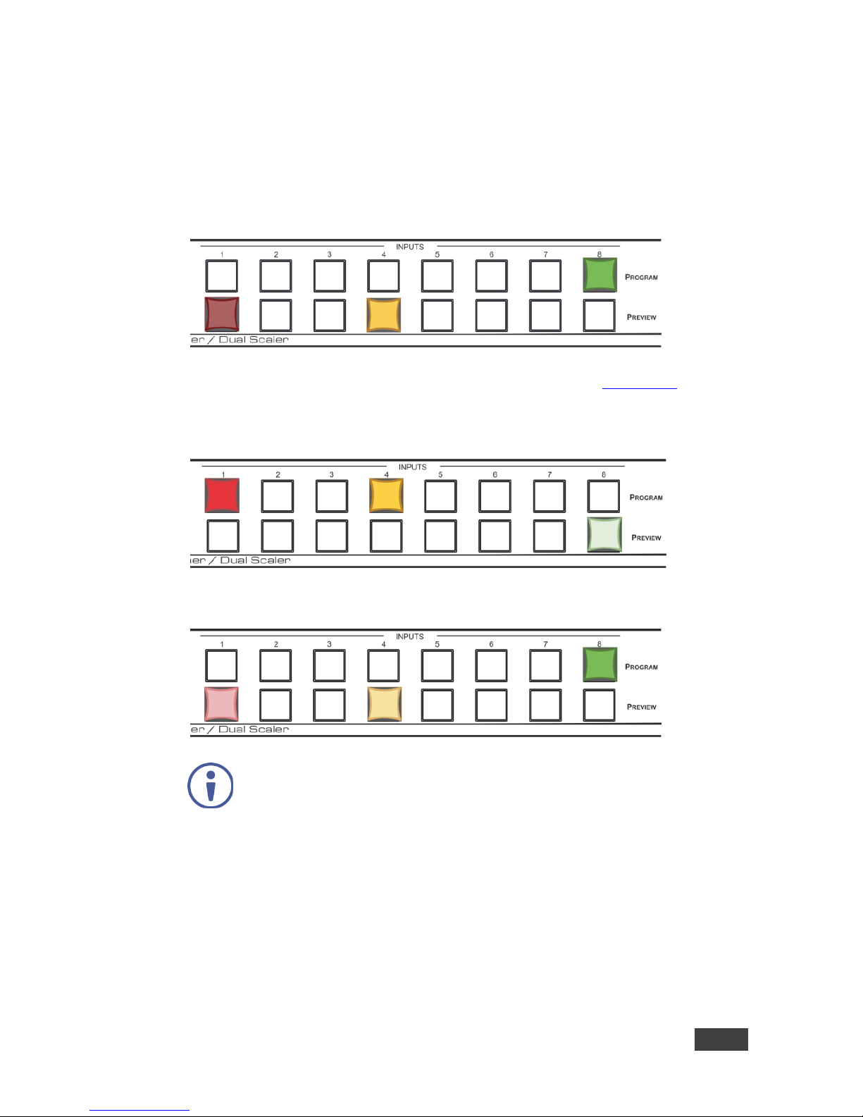
When in the Transition mode, pressing the ENTER front panel button in the Swap
mode will swap the Preview and Program inputs as follows, from:
TO
When in the Transition mode, pressing the ENTER front panel button in the Follow
mode will switch the Program inputs to follow the Preview inputs:
TO
Page 38
VP-772 - Controlling the VP-772
33
33
8.1.3 Button Behavior in the Overlay Mode
When in the overlay mode, the VP-772 does not pass the Preview audio to the
output.
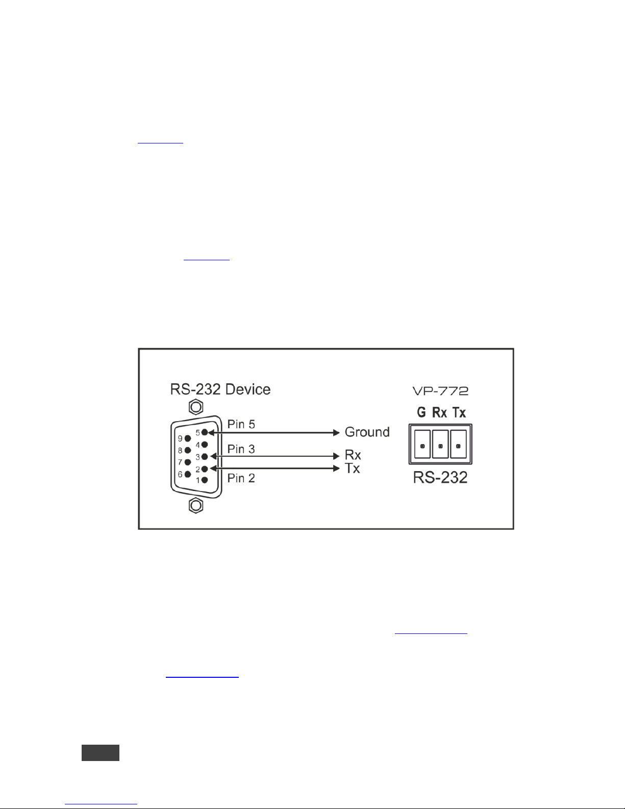
In the Overlay dual mode the preview audio input button is dimmed:
When in the Overlay mode, in the Single Window setting (see Section 6.3), the
Preview buttons (Audio, Video and AFV) appear dim, as illustrated in the following
examples:
Or
If you want to adjust the image of a selected input in a window, press
that input button again (up to 3 times) for fast tuning. Pressing that
input button for the fourth time initiates full tuning of the window.
Page 39
34
VP-772 - Controlling the VP-772
8.2 Controlling via the OSD Menu
You can change Preview/PiP Window parameters, Program/Main window
parameters and entire system parameters via the OSD menu, as described in
Section 6.
8.2.1 Connecting to the VP-772 via RS-232
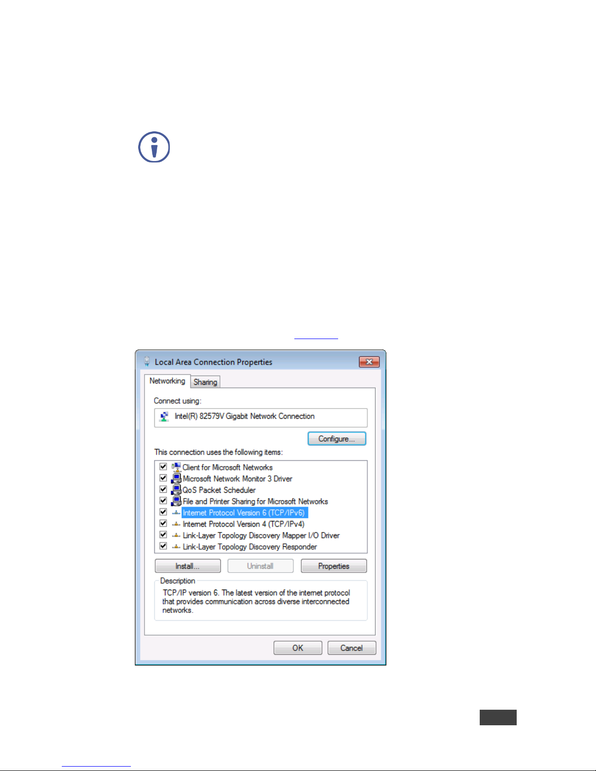
You can connect to the VP-772 via an RS-232 connection using, for example, a
PC. To connect the RS-232 terminal block on the rear panel of the VP-772 to a
PC/controller connect the RS-232 9-pin D-sub port on your device to controller as
shown in Figure 15, connect the VP-772 RS-232 terminal block:
TX pin to Pin 2
RX pin to Pin 3
GND pin to Pin 5
Figure 15: RS-232 Connection
8.2.2 Connecting the VP-772 via the ETHERNET Port
You can connect to the VP-772 via Ethernet using either of the following methods:
Directly to the PC using a crossover cable (see Section 8.2.2.1)
Via a network hub, switch, or router, using a straight-through cable (see
Section 8.2.2.2)
Note: If you want to connect via a router and your IT system is based on IPv6,
speak to your IT department for specific installation instructions.
Page 40
VP-772 - Controlling the VP-772
35
35
8.2.2.1 Connecting the Ethernet Port Directly to a PC
You can connect the Ethernet port of the VP-772 directly to the Ethernet port on
your PC using a crossover cable with RJ-45 connectors.
This type of connection is recommended for identifying the VP-772
with the factory configured default IP address.
After connecting the VP-772 to the Ethernet port, configure your PC as follows:
1. Click Start > Control Panel > Network and Sharing Center.
2. Click Change Adapter Settings.
3. Highlight the network adapter you want to use to connect to the device and
click Change settings of this connection.
The Local Area Connection Properties window for the selected network
adapter appears as shown in Figure 16.
Figure 16: Local Area Connection Properties Window
Page 41
36
VP-772 - Controlling the VP-772
4. Highlight either Internet Protocol Version 6 (TCP/IPv6) or Internet
Protocol Version 4 (TCP/IPv4) depending on the requirements of your IT
system.
5. Click Properties.
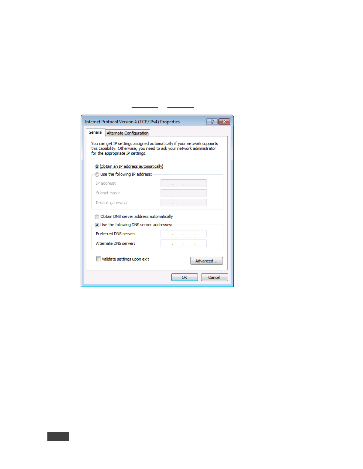
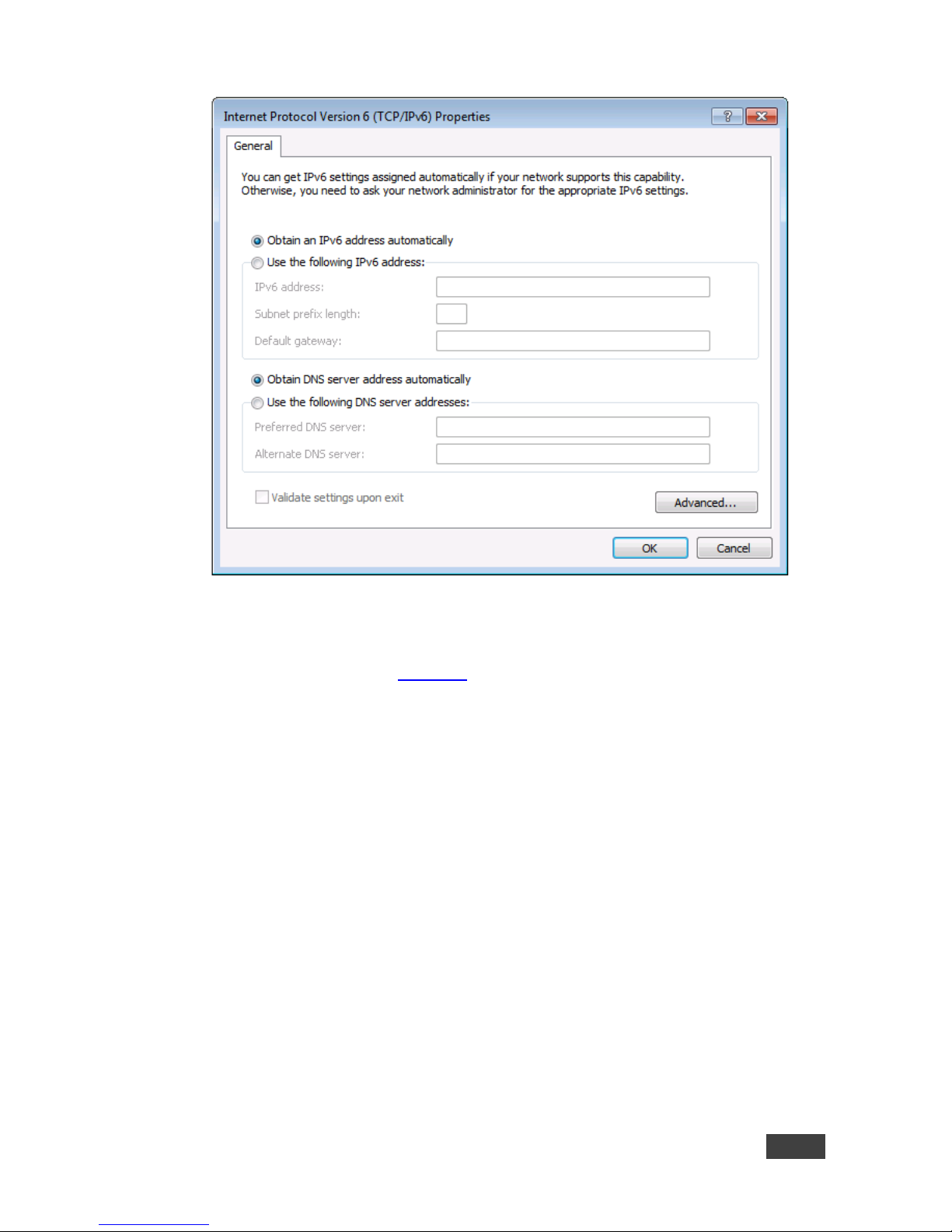
The Internet Protocol Properties window relevant to your IT system appears
as shown in Figure 17 or Figure 18.
Figure 17: Internet Protocol Version 4 Properties Window
Page 42
VP-772 - Controlling the VP-772
37
37
Figure 18: Internet Protocol Version 6 Properties Window
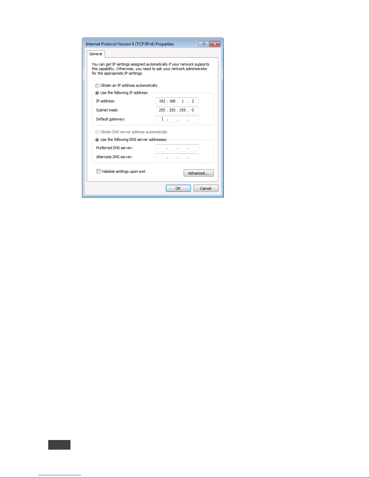
6. Select Use the following IP Address for static IP addressing and fill in the
details as shown in Figure 19.
For TCP/IPv4 you can use any IP address in the range 192.168.1.1 to
192.168.1.255 (excluding 192.168.1.39) that is provided by your IT
department.
Page 43
38
VP-772 - Controlling the VP-772
Figure 19: Internet Protocol Properties Window
7. Click OK.
8. Click Close.
8.2.2.2 Connecting the Ethernet Port via a Network Hub or
Switch
You can connect the Ethernet port of the VP-772 to the Ethernet port on a network
hub or using a straight-through cable with RJ-45 connectors.
Page 44
VP-772 - Controlling the VP-772
39
39
8.3 Controlling via the Infrared Remote Control Transmitter
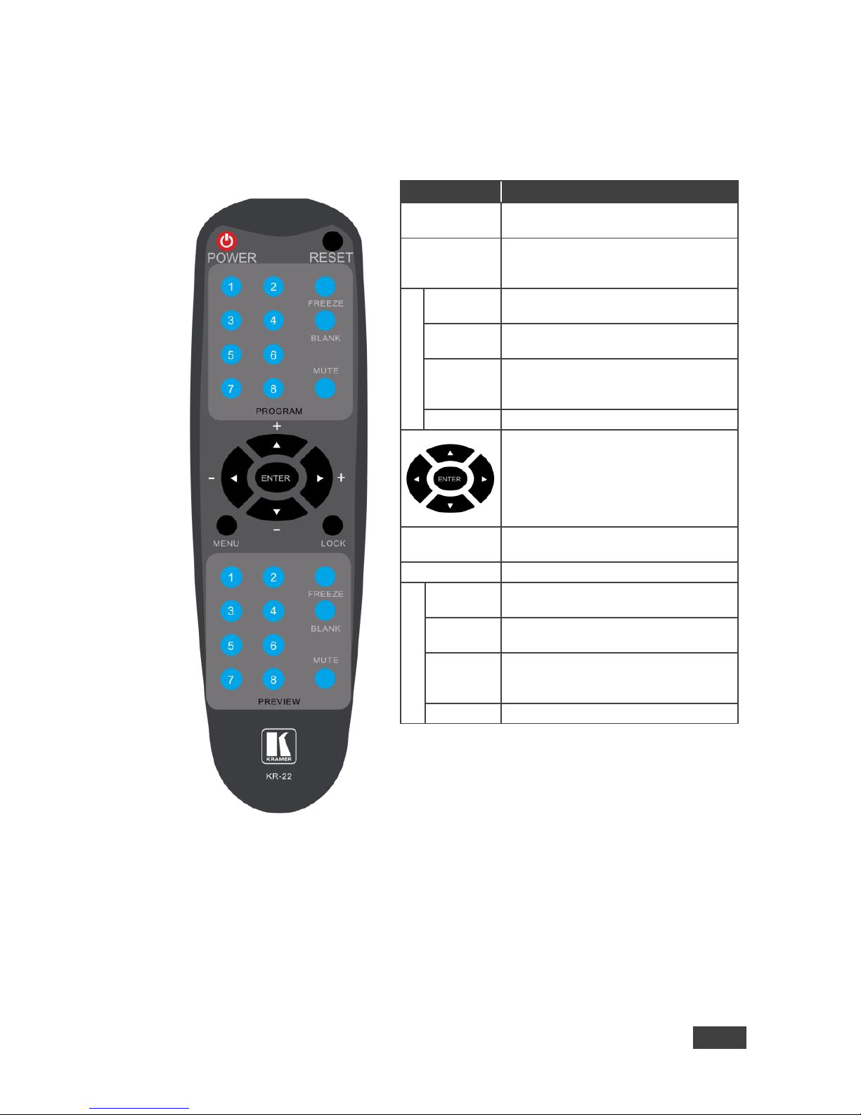
You can control the VP-772 from the infrared remote control transmitter:
Figure 20: Infrared Remote
Control Transmitter
Keys
Function
POWER
Toggle the power save mode ON or
OFF
RESET
Press to reset to the default resolution
(toggles between RESET TO XGA and
720p)
PROGRAM
FREEZE
Freeze/unfreeze the output video
image
BLANK
Toggle between a blank screen black
screen and the display
MUTE
Toggle between muting (blocking out
the sound) and enabling the audio
output
INPUTS
Select an input from 1 to 8
Press ENTER to access menu levels
(when in the OSD)
Use the up and down arrows to adjust
numerical values and adjust the output
volume level (when not within the
OSD)
MENU
Enter/Exit the OSD menu and return to
the previous menu level
LOCK
Lock the front panel buttons
PREVIEW
FREEZE
Freeze/unfreeze the output video
image
BLANK
Toggle between a blank screen black
screen and the display
MUTE
Toggle between muting (blocking out
the sound) and enabling the audio
output
INPUTS
Select an input from 1 to 8
8.3.1 Using the IR Transmitter
Page 45

40
VP-772 - Controlling the VP-772
You can use the IR transmitter to control the machine via the built-in IR receiver on
the front panel or, instead, via an optional external IR receiver (Model:
C-A35M/IRR-50). The external IR receiver can be located up to 15 meters away
from the machine. This distance can be extended to up to 60 meters when used
with three extension cables (Model: C-A35M/A35F-50).
Before using the external IR receiver, be sure to arrange for your Kramer dealer to
insert the internal IR connection cable (P/N: 505-70434010-S) with the 3.5mm
connector that fits into the REMOTE IR opening on the rear panel. Connect the
external IR receiver to the REMOTE IR 3.5mm connector.
Page 46
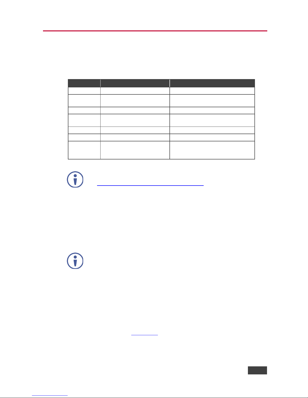
VP-772 - Firmware Upgrade
41
41
9 Firmware Upgrade
This section describes the firmware upgrade of the VP-772 components that are
described in the table below:
File Type
Description
Becomes Effective After
RBF
An *.rbf file to upgrade FPGA
VP-772 application restart
Memory
upgrades the other Alteras and
the OSD bitmap
VP-772 application restart
Application
The main VP-772 application
VP-772 application restart
Linux kernel
Includes all drivers for the
VP-772 board
Rebooting the board
Cramfs
A read only Linux file system
Rebooting the board
Bootloader
Launches the Linux kernel
Rebooting the board
Jffs2
A read/write file system
including the RBF and Memory
files, as well as the application
Rebooting the board
The latest firmware version can be downloaded from the Kramer Web site
at http://www.kramerav.com/downloads/VP-772
9.1 The Firmware Upgrade Process
Unzip the firmware files on your desktop to a folder named “VP-772” and then copy
that folder to an empty, FAT32-formated USB memory stick (with at least 30Mb of
free space) as a root folder. After copying the “VP-772” folder as a single root
folder, the USB memory stick is ready to be used by attaching it into the device.
Make sure that you remove the USB memory stick safely from your PC.
Failing to do so may corrupt the firmware files on the memory stick
To upgrade the firmware:
1. Connect the USB memory stick to the S/W UPGRADE USB port on the rear
panel of the VP-772.
2. On the front panel click the MENU button, select FW Upgrade and then
select Upgrade (see Section 6.5).
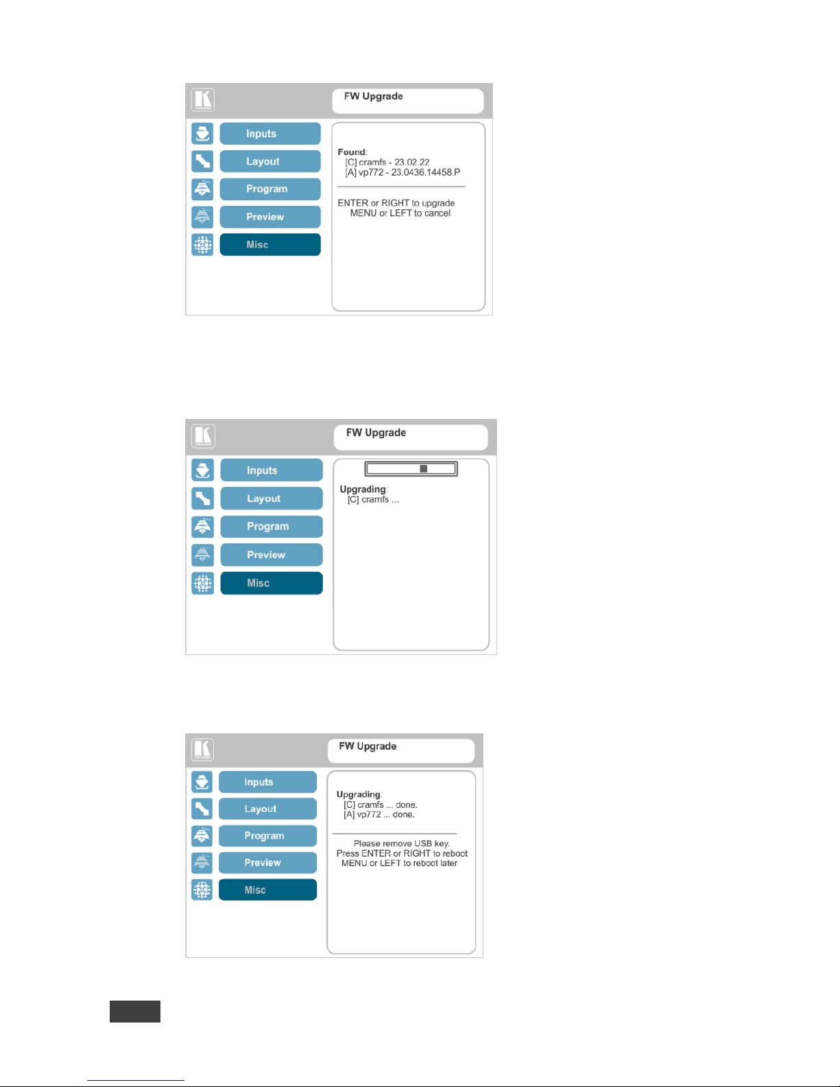
The OSD shows the firmware version found in the memory stick:
Page 47
42
VP-772 - Firmware Upgrade
Figure 21: Firmware Upgrade – list of Files to Upgrade
3. Click the ENTER button on the front panel.
Wait for the completion of the upgrade process:
Figure 22: Firmware Upgrade – Upgrade Process
When the firmware upgrade is complete, the list of upgraded files appears:
Figure 23: Firmware Upgrade – Upgrade Complete
Page 48
VP-772 - Firmware Upgrade
43
43
4. Remove the USB memory stick and click the ENTER button on the front
panel to reboot the system.
9.2 Rollback
The Rollback feature lets you restore the previous firmware version installed by the
user. To do so:
1. On the front panel click the MENU button, select FW Upgrade and then
select Rollback (see Section 6.5).
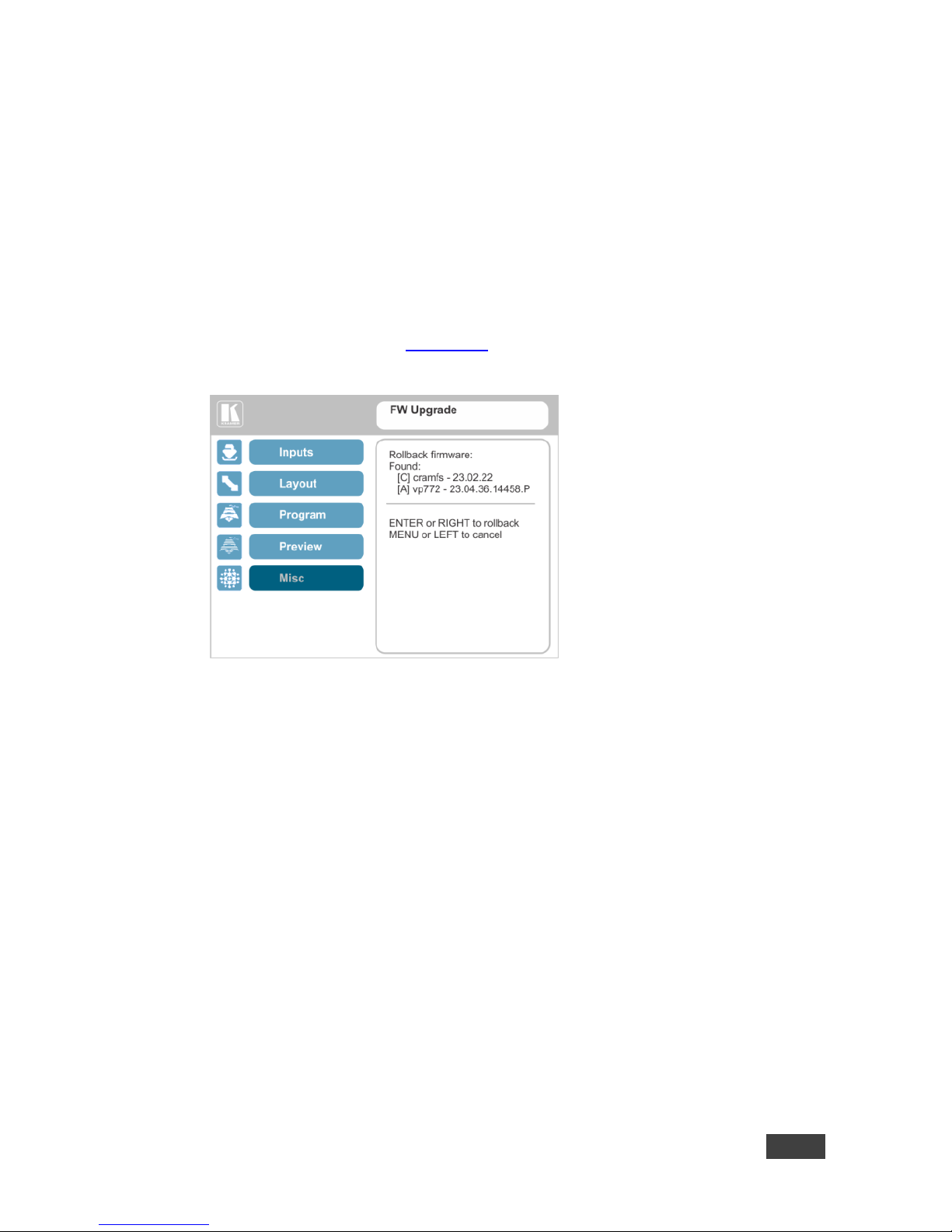
The OSD shows the firmware version found in the system:
Figure 24: Firmware Upgrade – list of Files to Rollback
2. Press the ENTER button or the left arrow to proceed.
Wait for completion of the procedure.
3. Reboot the machine by turning it off and then on again.
Page 49
44
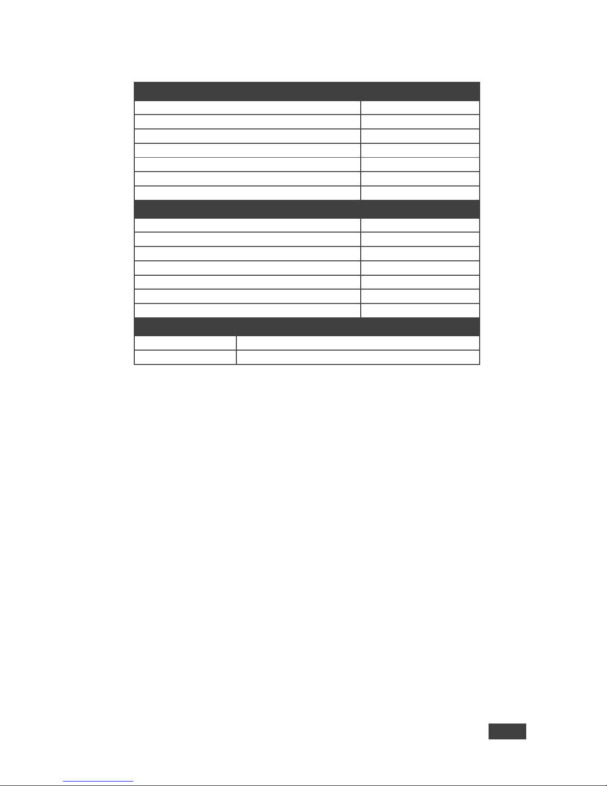
VP-772 - Technical Specifications
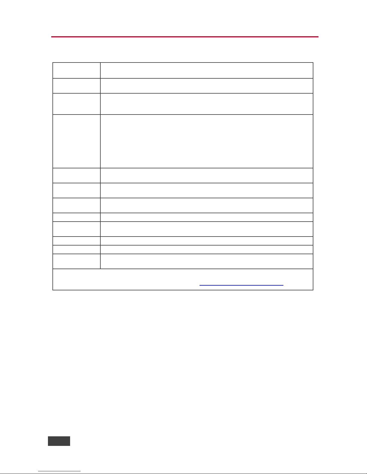
10 Technical Specifications
INPUTS:
8 DVI-U inputs (DVI-D, HDMI, PC, YPbPr and CV) on DVI-I connectors
8 balanced stereo audio on 5-pin terminal block connectors
OUTPUTS:
2 DVI-I outputs (DVI-D, HDMI and PC) on DVI-I connectors2 balanced stereo audio
on 5-pin terminal block connector
COMPLIANCE
WITH HDMI
STANDARD:
Supports HDMI (deep color) and HDCP
OUTPUT
RESOLUTIONS:
640x480@60, 640x480@75, 800x600@50, 800x600@60, 800x600@75,
1024x768@50, 1024x768@60, 1024x768@75, 1280x768@50, 1280x768@60,
1280x800@60, 1280x1024@50, 1280x1024@60, 1280x1024@75, 1360x768@60,
1366x768@50, 1366x768@60, 1400x1050@50, 1400x1050@60, 1600x900@60,
1600x1200@50, 1600x1200@60, 1680x1050@60, 1920x1200@60RB, 480p60,
576p50, 720p50, 720p59.94, 720p60, 1080p23.976, 1080p24, 1080p25,
1080p29.97, 1080p30, 1080p50, 1080p59.94, 1080p60, 1080i50, 1080i60, 2k50,
2k60, 4k2k@30
CONTROLS:
Front panel buttons, OSD, IR remote control, RS-232 on a 9-pin D-sub connector,
Ethernet
OPERATING
TEMPERATURE:
0° to +40°C (32° to 104°F)
STORAGE
TEMPERATURE:
-40° to +70°C (-40° to 158°F)
HUMIDITY:
10% to 90%, RHL non-condensing
POWER
CONSUMPTION:
100-240V AC, 42VA max.
DIMENSIONS:
19" (W), 9.3" (D) 1U (H) rack mountable
WEIGHT:
4.3kg (9.5lbs) approx.
INCLUDED
ACCESSORIES:
Power cord, rack “ears”, IR remote control, 2 DVI-A (M) to 5 BNC (F) Adapter
Cables (ADC-DMA/5BF-1), 2 DVI (M) to 15-pin HD (F) Adapters (AD-DM/GF)
Specifications are subject to change without notice
For the most updated resolution list, go to our Web site at http://www.kramerelectronics.com
Page 50
VP-772 - Technical Specifications
45
45
10.1 Default Communication Parameters
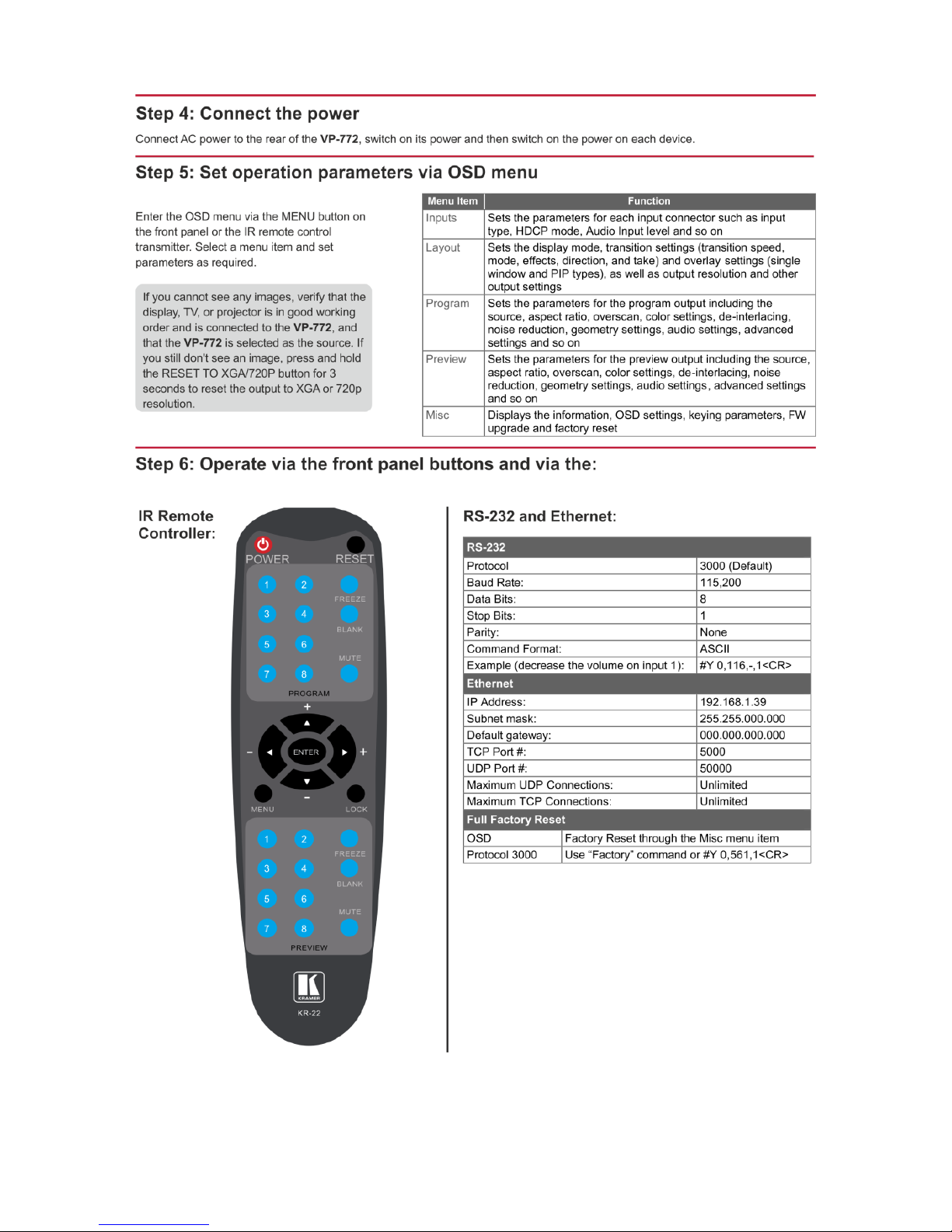
RS-232
Protocol
3000 (Default)
Baud Rate:
115,200
Data Bits:
8
Stop Bits:
1
Parity:
None
Command Format:
ASCII
Example (decrease the volume on input 1):
#Y 0,116,-,1<CR>
Ethernet
IP Address:
192.168.1.39
Subnet mask:
255.255.000.000
Default gateway:
000.000.000.000
TCP Port #:
5000
UDP Port #:
50000
Maximum UDP Connections:
Unlimited
Maximum TCP Connections:
Unlimited
Full Factory Reset
OSD
Factory Reset through the Misc menu item
Protocol 3000
Use “Factory” command or #Y 0,561,1<CR>
Page 51
46
VP-772 - Technical Specifications
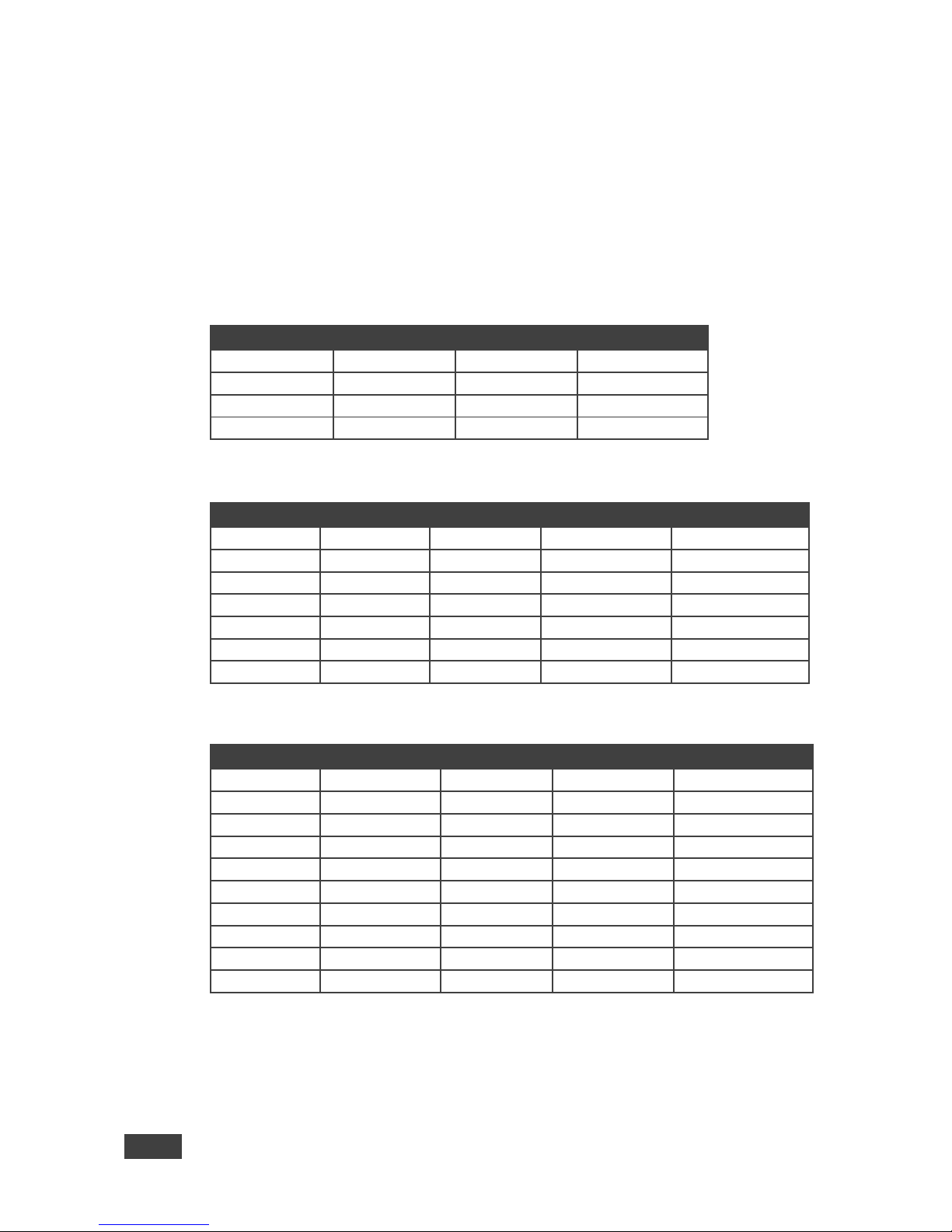
10.2 Input Resolutions
The VP-772 features eight DVI-U inputs. This section defines the input resolutions
for each input.
10.2.1 CV Input Resolutions
NTSC and PAL
10.2.2 Component Analog Video (YPbPr) Input Resolutions
PC Input Resolutions
NTSC
720_P50
1080_P30
1080_P50
PAL
720_P60
1080_P23_976
1080_P60
525_P60
1080_I50
1080_P24
1080_P100
625_P50
1080_I60
1080_P25
10.2.3 RGBHV Analog Video Input Resolutions
RGBHV Input Resolutions
640X480_60
800x600_75
625_P50
1280x1024_60
1400x1050_75
640x480_72
800x600_85
525_P60
1280x1024_75
1600x900_60
640x480_75
1024x768_60
720_P50
1280x1024_85
1600x1200_60
640x480_85
1024x768_70
720_P60
1360x768_60
1680x1050_60
800x600_56
1024x768_75
1280x800_60
1366x768_60
1920x1200_60RB
800x600_60
1024x768_85
1280x960_85
1440x900_60
1080_P50
800x600_72
1152x864_75
1280x768_60
1400x1050_60
1080_P60
10.2.4 HDMI Digital Video Input Resolutions
HDMI Input Resolutions
NTSC
1080_I60
640x480_72
1024x768_70
1360x768_60
PAL
1080_P23_976
640x480_75
1024x768_75
1366x768_60
525_P60
1080_P24
640x480_85
1024x768_85
1440x900_60
625_P50
1080_P25
800x600_56
1152x864_75
1400x1050_60
720_P24
1080_P30
800x600_60
1280x800_60
1400x1050_75
720_P25
1080_P50
800x600_72
1280x960_85
1600x900_60
720_P30
1080_P60
800x600_75
1280x768_60
1600x1200_60
720_P50
2k50
800x600_85
1280x1024_60
1680x1050_60
720_P60
2k60
848x480_60
1280x1024_75
1920x1200_60RB
1080_I50
640X480_60
1024x768_60
1280x1024_85
Page 52
VP-772 - Technical Specifications
47
47
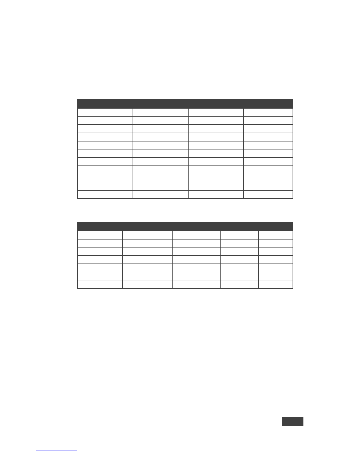
10.3 Output Resolutions
The VP-772 features two DVI-I outputs. This section defines the output resolutions
for each output.
10.3.1 HDMI Digital Video Output Resolutions
Technical Specifications of the HDMI Output Signal
640x480@60
1280x1024@50
1680x1050@60
1080p30
640x480@75
1280x1024@60
1920x1200@60
1080p50
800x600@50
1280x1024@75
480p60
1080p59.94
800x600@60
1360x768@60
576p50
1080p60
800x600@75
1366x768@50
720p50
1080i50
1024x768@50
1366x768@60
720p59.94
1080i60
1024x768@60
1400x1050@50
720p60
2k50
1024x768@75
1400x1050@60
1080p23.976
2k60
1280x768@50
1600x900@60
1080p24
4k2k@30
1280x768@60
1600x1200@50
1080p25
1280x800@60
1600x1200@60
1080p29.97
10.3.1 RGBHV Analog Video Output Resolutions
RGBHV Output Resolutions
640x480@60
1280x800@60
1600x1200@60
720p60
1080p59.94
640x480@75
1280x1024@60
1680x1050@60
1080p23.976
1080p60
800x600@60
1280x1024@75
1920x1200@60
1080p24
1080i50
800x600@75
1360x768@60
480p60
1080p25
1080i60
1024x768@60
1366x768@60
576p50
1080p29.97
2k50
1024x768@75
1400x1050@60
720p50
1080p30
2k60
1280x768@60
1600x900@60
720p59.94
1080p50
Page 53
48
VP-772 - The VP-772 RS-232 Communication Protocol
11 The VP-772 RS-232 Communication
Protocol
The Kramer Protocol lets you control the VP-772 from any standard terminal
software (for example, the Windows® HyperTerminal Application).
11.1 Using the Communication Protocol
There are three different methods to control the VP-772 RS-232 or the Ethernet:
Protocol commands mimicking the OSD, see Section 11.2
The button functions mimicking the remote controller buttons (as well as the
front panel buttons), see Section 11.3
Protocol 3000 common commands, see Section 11.4
All three tables together include all the protocol commands, but they are
not identical and do not always include the same information. Some of
the data may appear in one or two of the tables but not in the third table
and vice versa.
The protocol 3000 communications protocol uses a data rate of 115200 baud, with
no parity, 8 data bits, and 1 stop bit.
11.2 Communication Protocol: Mimicking OSD
The audio/video protocol commands define all the function numbers, their valid
parameters can be used with protocol 3000.
11.2.1 Using the Communication Protocol with Protocol 3000
(the “Y” Command)
Set Command:
Type in: “Y Control_Type=0,Function,Param”
Reply: “~id=01Y Control_Type=0,Function,Param OK”
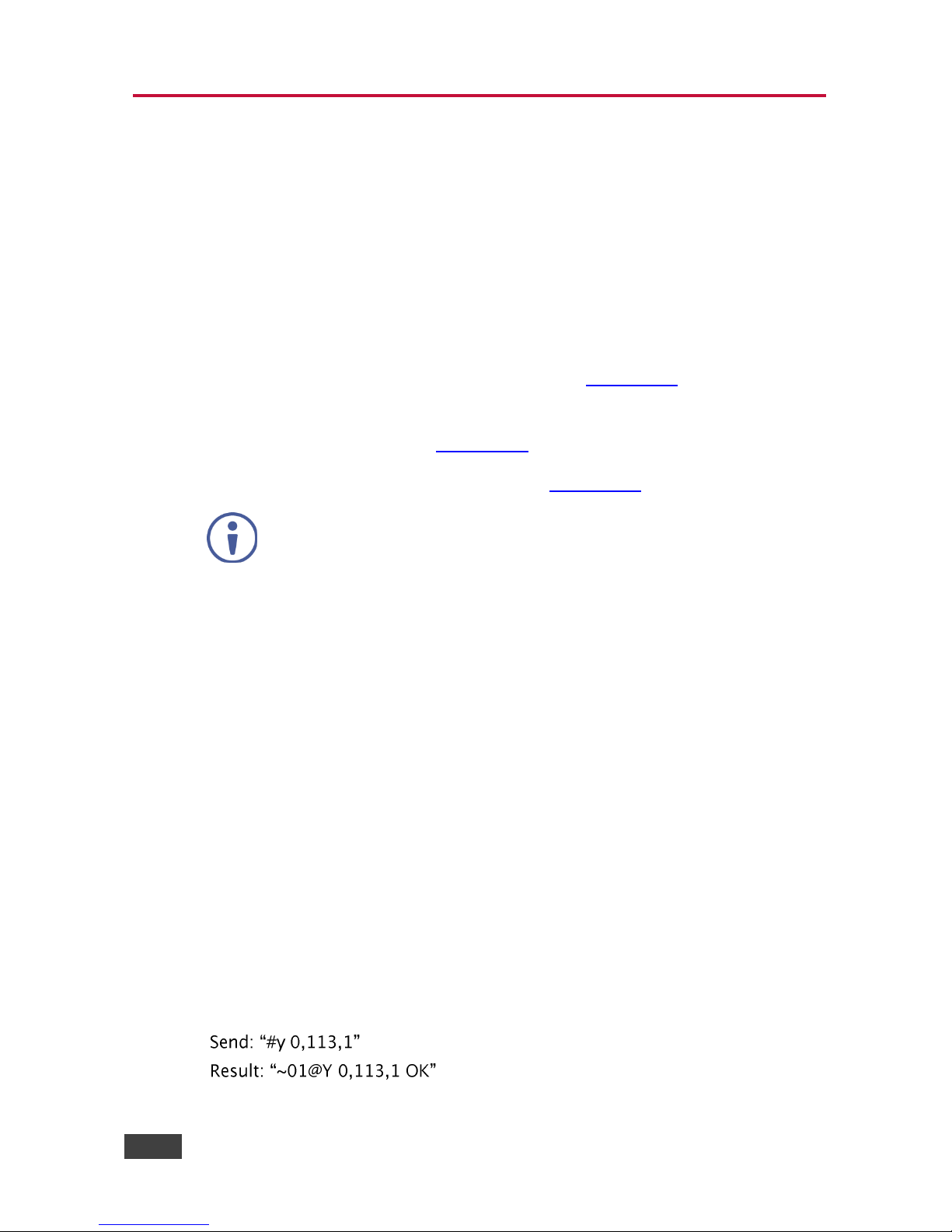
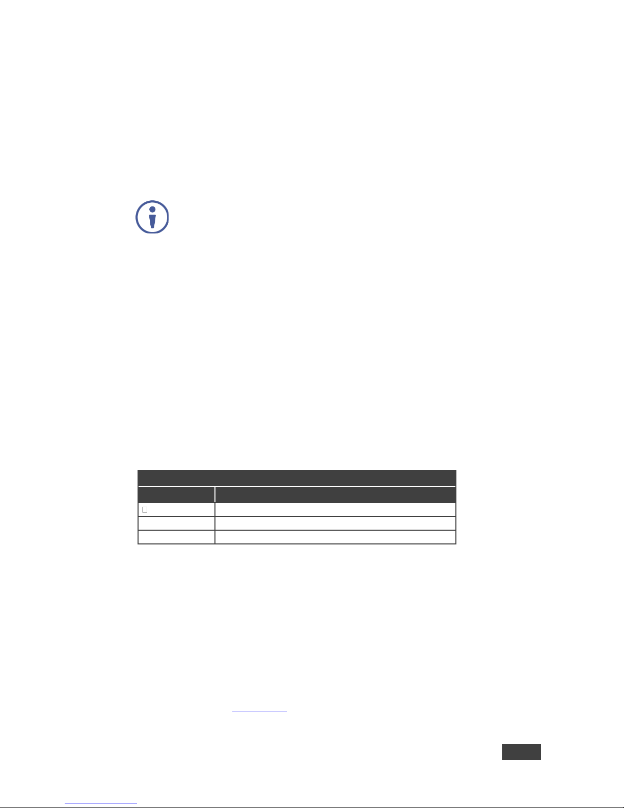
Set command example: set HDCP mode for input 1 (113) to “On”
Page 54
VP-772 - The VP-772 RS-232 Communication Protocol
49
49
Get Command:
Type in: “Y Control_Type=1,Function”
Result: “~id=01Y Control_Type=1,Function,Param”
Get command example: get HDCP mode for input 1 (113):
Send: “#y 1,113”
Result: “~01@y 1,113,1”
You can add a last parameter, to be located fourth in SET or third in GET,
to define a specific window.
For example:
Set H Sharpness value to 10 on the Program window (1): “#y 0,343,10, 1”
Get H sharpness of the Main window (0): “#y 1,343,0”
The “Y” command also supports the value increment/decrement of any command
using the ‘+’ or ‘-‘ signs as the third parameter of the “Y” command.
For example, in order to decrease the volume on input 1 (116)
Send: “#Y 0,116,-,1<CR>”
Reply: “~01@Y 0,116,-,1 OK”
Note that if the value after the decrease is out of range, the reply will show an error
such as:”~01@Y ERR -03”
Character Symbols Definitions
Symbol
Meaning
Space
[CR]
Carriage Return, ASCII code 0x0D
[LF] or >
Line Feed, ASCII code 0x0A
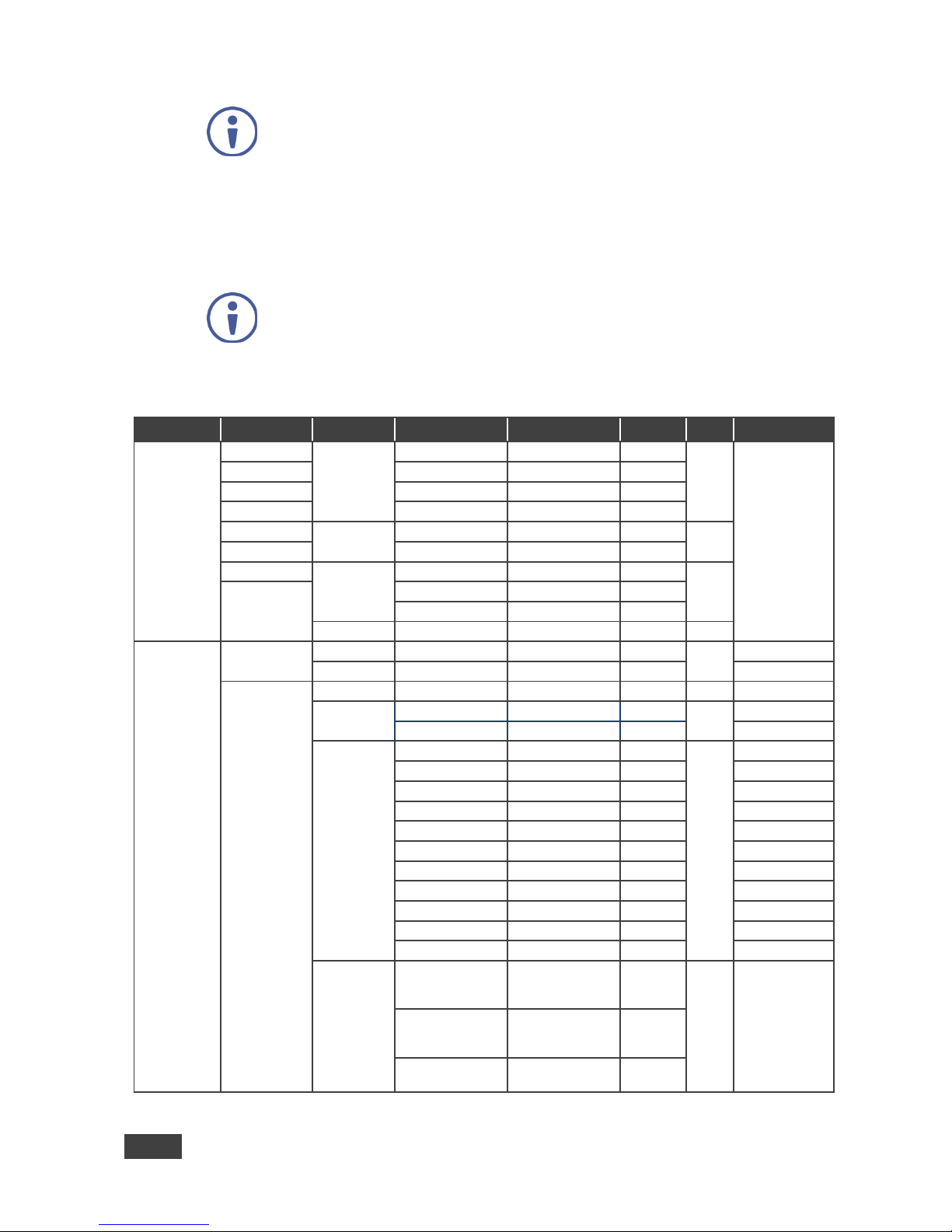
11.2.2 Protocol Table: Mimicking OSD
You can associate a function number to its description and valid parameters
intuitively by navigating the OSD menu according to the following logic:
A function number is directly related to its location in the OSD menu.
For example, the second menu on the OSD is Layout (2 in the hundreds). The third
menu item in Layout is Overlay Settings (2 in the tens), therefore the function
number for it will be 230 (2nd item on the Main menu and the 3rd item in the Layout
submenu (see also Section 6.1). When navigating in the OSD MENU you will be
able to see the Overlay Settings valid parameters.
Page 55
50
VP-772 - The VP-772 RS-232 Communication Protocol
Note that for the Inputs, menu levels 3, 4 and 5 are valid for each input
from 1 to 8. For example, Type (3rd level) item is 111 for Input 1 and 121
for Input 2, and so on. In order not to repeat the Inputs menu for each
input, the function list will have an x denoting the input number from 1 to 8.
For example the Type item will have 1x1 as the function number x being
from 1 to 8.
The following table shows the Program function numbering.
Note that some items that appear in red on the OSD menu seem missing
in the table below. These items will be enabled in future firmware and will
be described in detail.
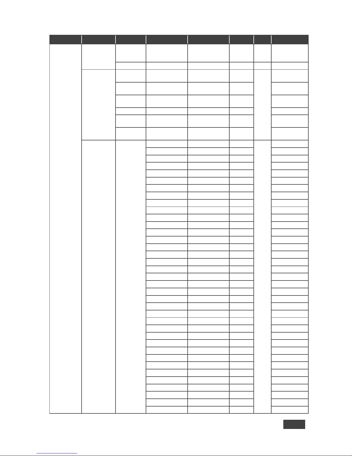
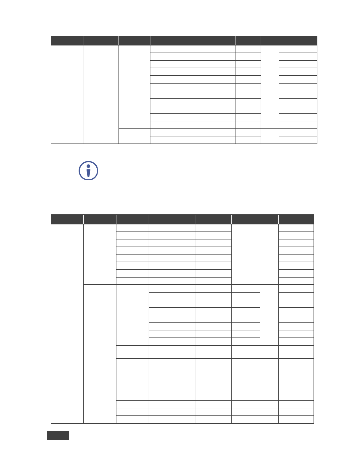
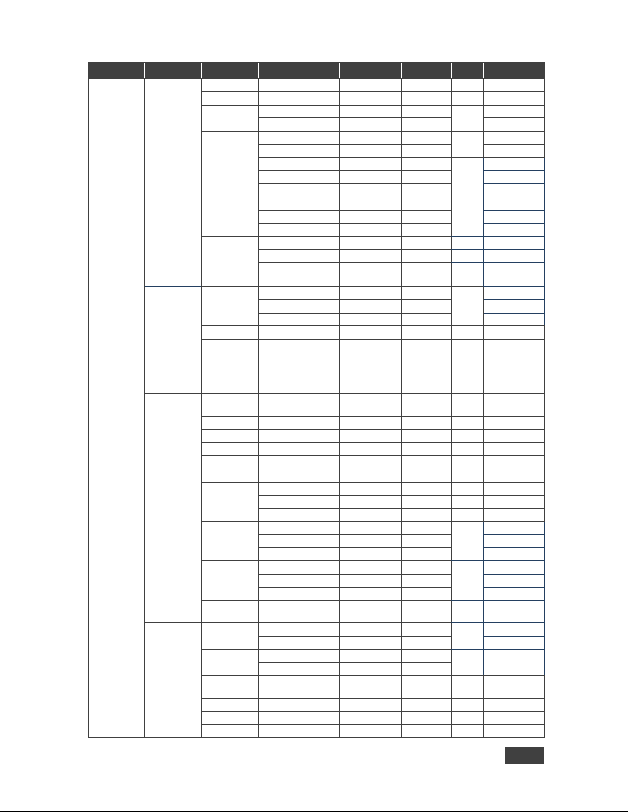
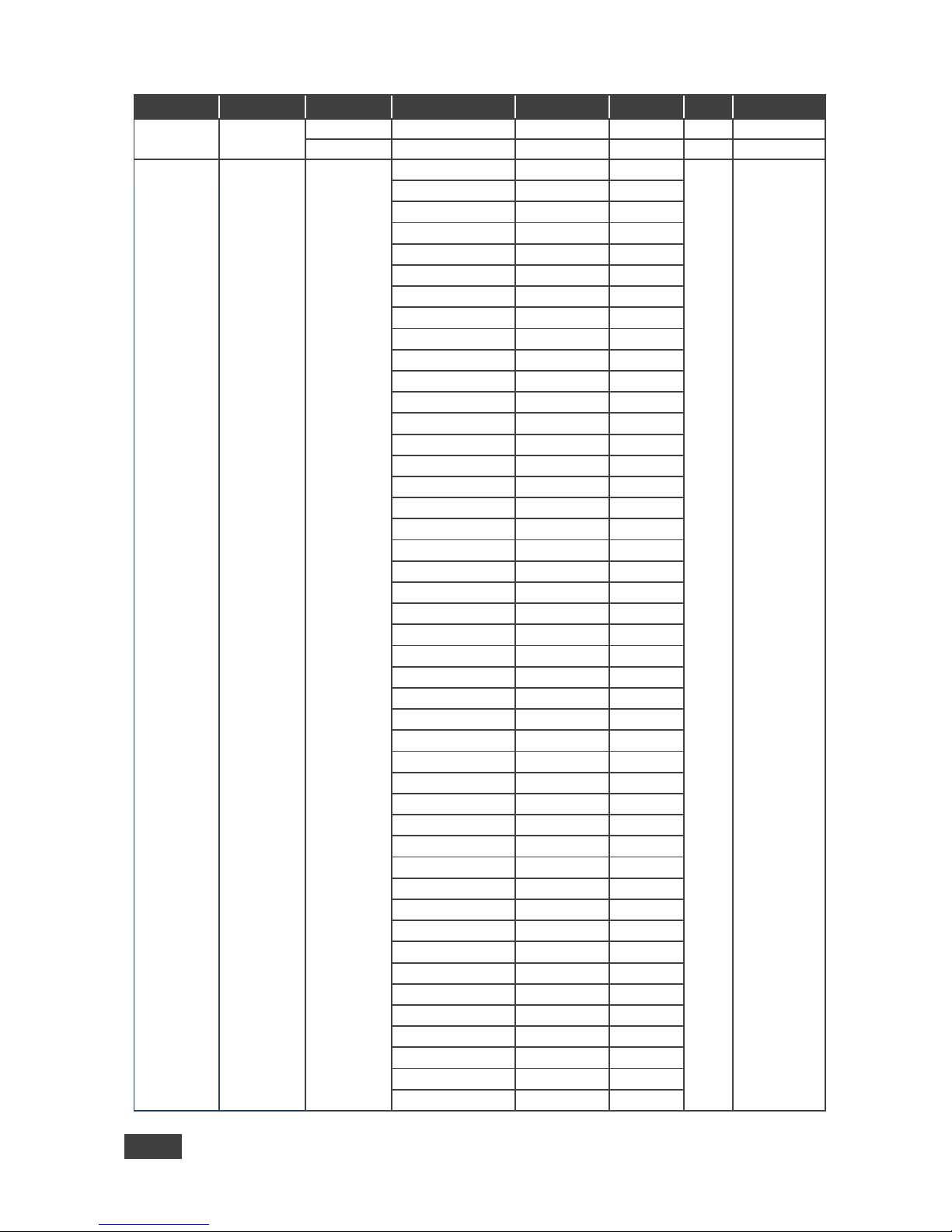
The following table defines the protocol commands:
1st Level
2nd Level
3rd Level
4th Level
5th Level
Range
Func.
Notes
Inputs
Input 1
Type
HDMI
0 1x1
Input 2
YUV 1
Input 3
VGA 2
Input 4
CV 3
Input 5
HDCP Mode
On 0
1x3
Input 6
Off 1
Input 7
Color Space
RGB 0
1x5
Input 8
YPbPr
1
Follow Input
2
Volume
[-20:+4]
1x6
Layout
Display Mode
Transition
0
210 Overlay
1
Transition
Settings
Speed
[1:15]
221
Mode
Swap
0 222 Follow
1
Effect
Cut 0
223 Fade
1
Diagonal
2
Wipe
3 Circle
4 Square
5 Diamond
6 Triangle
7 Curtain
8
Chessboard
9
Blinds
10
Direction
Left to Right /
From Top Left /
Inbound
0
224
the point of
entry of the
transition will be
available
depending on
the selected
effect
Right to Left /
From Bottom Left
/ Outbound
1
Up / From Top
Right / Horizontal
2
Page 56
VP-772 - The VP-772 RS-232 Communication Protocol
51
51
1st Level
2nd Level
3rd Level
4th Level
5th Level
Range
Func.
Notes
Down / From
Bottom Right /
Vertical
3
Take 225
Overlay
Settings
Single
Window
0
230
Picture in
Picture
1
Picture +
Picture
2
Split 3
Customized
Single
4
Customized
Dual
5
Output
Video
Resolution
NATIVE
0 241 640x480p60
1
640x480p75
2
800x600p50
3
800x600p60
4
800x600p75
5
1024x768p50
6
1024x768p60
7
1024x768p75
8
1280x768p50
9
1280x768p60
10
1280x800p60
11 1280x1024p50
12 1280x1024p60
13 1280x1024p75
14
1360x768p60
15
1366x768p50
16 1366x768p60
17 1400x1050p50
18 1400x1050p60
19
1600x900p60
20
1600x1200p50
21 1600x1200p60
22 1680x1050p60
23 1920x1200p60RB
24 480p60
25 576p50
26
720p50
27
720p59_94
28
720p60
29 1080p23_976
30 1080p24
31
1080p25,
32
1080p29_97
33 1080p30
34 1080p50
35 1080p59_94
36
Page 57
52
VP-772 - The VP-772 RS-232 Communication Protocol
1st Level
2nd Level
3rd Level
4th Level
5th Level
Range
Func.
Notes
1080p60
37
1080i50
38 1080i60
39 2k50 40 2k60 41 4k2k30
42
Master
Connection
Program
0 242
Preview
1
Color Space
RGB 0
244 YPbPr422
1 YPbPr444
2
HDCP Mode
Follow Output
0 245
Follow Input
1
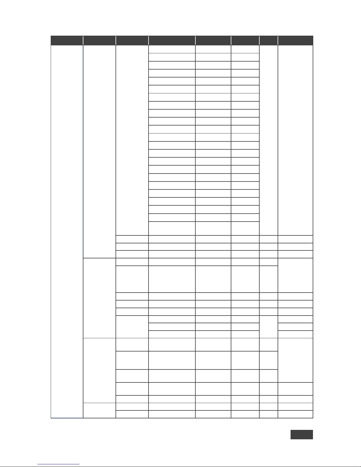
The Program and the Preview menus are identical therefore one table is
shown for both. The only difference would be in the function number:
Program functions start with a 3 and Preview functions start with a 4.
For example, Aspect ratio is 321 for the Program aspect ratio and 421 for
the Preview aspect ratio.
1st Level
2nd Level
3rd Level
4th Level
5th Level
Range
Func.
Notes
Program(3xx)
/
Preview(4xx)
Source
Input 1
[1:8]
310
Input 2
Input 3
Input 4
Input 5
Input 6
Input 7
Input 8
Scaling
Aspect Ratio
Follow Input
0 321
Follow Output
1 Best Fit
2 Letterbox
3
Overscan
Follow Input
0 322
Off 1
5% 2
10% 3
Ratio Shift
mode
Auto 0
323
H Image Shift
[-50:+1023]
325
The value
range is
dynamic, FW
prevents
exceeding of
boundaries
V Image Shift
[-10:+1023]
326
Picture
Brightness
[-512:+512]
341
Contrast
[10:160]
342 H Sharpness
[-10:+10]
343 V Sharpness
[-10:+10]
344
Page 58
VP-772 - The VP-772 RS-232 Communication Protocol
53
53
1st Level
2nd Level
3rd Level
4th Level
5th Level
Range
Func.
Notes
Color
Chroma
[0:400]
351
Hue
[-180:+180]
352
Color
Temperature
6500k
0 353 9300k
1
Gamma
Mode
Gamma Off
0 354 Gamma 0.4
1 Gamma 0.8
2
Gamma 1.2
3
Gamma 1.6
4 Gamma 2.0
5 Gamma 2.4
6 Gamma 2.8
7
Color
Correction
Blue [0:4]
355
Green
[0:4]
356
Flesh
[0:4]
357
Deinterlacing
Film Mode
Off 0
361 Follow Input
1 24PsF Mode
2 PD Time
[0:15]
362
Motion
Detection
Sensitivity
LEVEL1-5
[0:4]
363
Diagonal
Correction
[0:3]
364
Noise
Reduction
Horizontal
NR
[0:3]
371
Vertical NR
[0:3]
372
Temporal NR
[0:3]
373 Block NR
[0:3]
374 Mosquito NR
[0:3]
375 Combing NR
[0:3]
376
Pause
Freeze
On / Off
[0:1]
3831
Blank
On / Off
[0:1]
3832 Mute
On / Off
[0:1]
3833
Test Pattern
Off 0
385 Slide Bar
1
Color Bar
2
No Signal
Gray 0
386 Blue 1
Black
2
Auto
Switching
387
Audio
Source
AFV 0
391
[1-8] [1-8]
AFV Source
Embedded
0 392
Analog
1
Output
Volume
[-80:+20]
393
Bass
[-18:+18]
394 Mid
[-18:+18]
395
Treble
[-18:+18]
396
Page 59
54
VP-772 - The VP-772 RS-232 Communication Protocol
1st Level
2nd Level
3rd Level
4th Level
5th Level
Range
Func.
Notes
Balance
[-10:+10]
397
Lip Sync
[0:90]
398
Misc
Information
Program/
Preview
NTSC
0
511/
512
READ ONLY:
In the OSD
MENU - Input,
Output video
formats & FW
version.
In the protocol
– Get
command
returns the
Input video
format only
PALM
1
PAL60
2
N443
3
NTSC_4
4
SECAM
5
PAL 6
PALNC
7
NTSC_8
8
N\A 9
N\A 10
N\A 11
N\A 12
N\A 13
525p60
14
625p50
15
720p60
16
720p50
17
720p24
18
720p25
19
720p30
20
1080i60
21
1080i50
22
N\A 23
1080i100
24
1080p60
25
1080p50
26
1080p30
27
1080p23_976
28
1080p24
29
1080p25
30
2k50
31
2k60
32
640X480@60
33
N\A 34
N\A 35
N\A 36
640x480@72
37
640x480@75
38
848x480@60
39
640x480@85
40
N\A 41
800x600@56
42
800x600@60
43
N\A 44
Page 60
VP-772 - The VP-772 RS-232 Communication Protocol
55
55
1st Level
2nd Level
3rd Level
4th Level
5th Level
Range
Func.
Notes
800x600@72
45
800x600@75
46
800x600@85
47
1024x768@60
48
1360x768@60
49
1280x768@60
50
1024x768@70
51
1024x768@75
52
1280x800@60
53
1024x768@85
54
1400x1050@60
55
1400x1050@75
56
1440x900@60
57
1152x864@75
58
1600x900@60
59
1280x1024@60
60
1280x1024@75
61
1280x960@85
62
1920x1200@60RB
63
1280x1024@85
64
1600x1200@60
65
1680x1050@60
66
NONE
0XF5 or
0XFF
Preview
512
FW Versions
513 Network
514
OSD
H Position
[0:2047]
521
The value
range is
dynamic, FW
prevents
exceeding of
boundaries
V Position
[0:2047]
522
Transparent
On / Off
[0:1]
523 Gain
[1:4]
524
Bias
[-128:+127]
525
Timeout
Off 0
526 30 Sec
1 60 Sec
2
Keying
Chroma
Keying Red
[0:240]
531
In steps of 16
Chroma
Keying
Green
[0:240]
532
Chroma
Keying Blue
[0:240]
533
Chroma
Keying
On / Off
[0:1]
534
Luma Keying
On / Off
[0:1]
535
FW Upgrade
Upgrade
541 Rollback
542
Page 61
56
VP-772 - The VP-772 RS-232 Communication Protocol
1st Level
2nd Level
3rd Level
4th Level
5th Level
Range
Func.
Notes
Factory
Reset
Including
ETH
561
Excluding
ETH
562
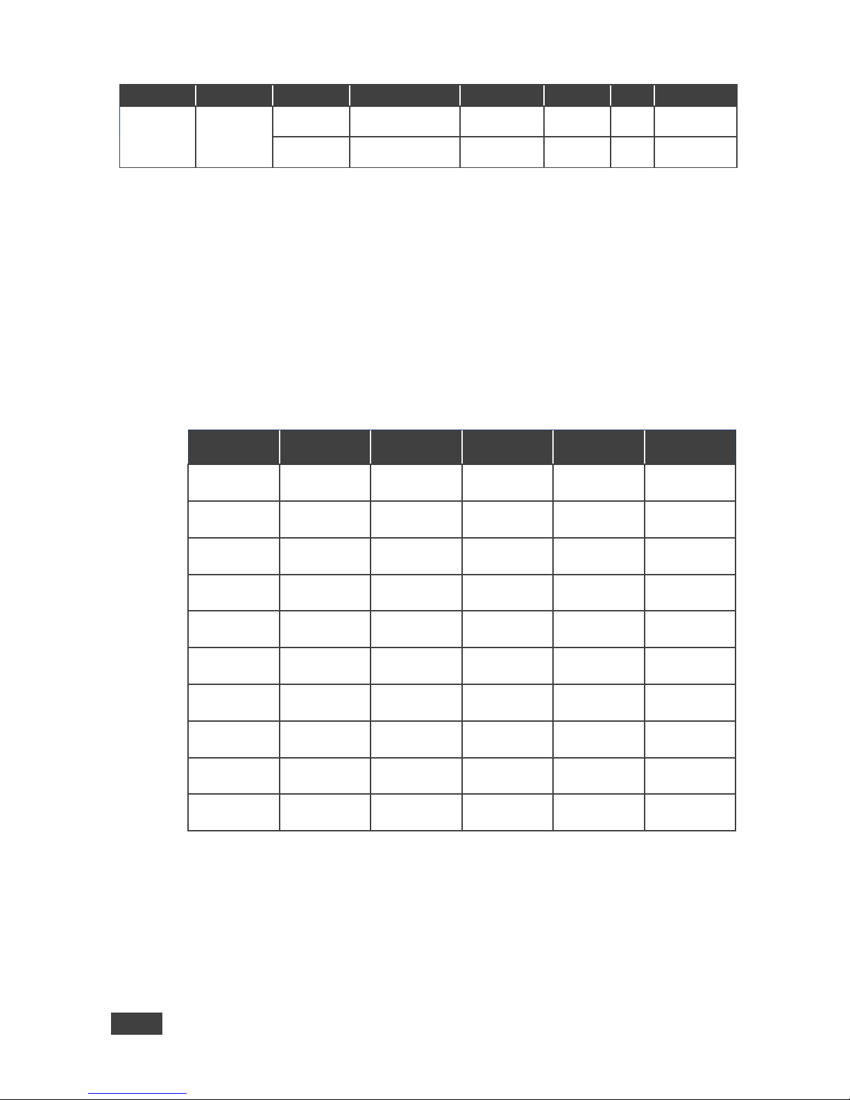
11.3 Protocol Table: Mimicking Remote and Front Panel
Buttons
The keystroke codes operate in the following way:
SET command third parameter =0,
Syntax example: "#Y 0,20,0<CR>" => MENU keystroke
GET command for keystrokes will return ERR
The following table defines the keystroke function codes:
Button
Keystroke
Code
Button
Keystroke
Code
Button
Keystroke
Code
MENU
20
PREVIEW
FREEZE
30
PROGRAM
INPUT 8
40
ENTER
21
PROGRAM
BLANK
31
PREVIEW
INPUT 1
41
DOWN
(MINUS)
22
PROGRAM
FREEZE
32
PREVIEW
INPUT 2
42
UP (PLUS)
23
PROGRAM
INPUT 1
33
PREVIEW
INPUT 3
43
LEFT
24
PROGRAM
INPUT 2
34
PREVIEW
INPUT 4
44
RIGHT
25
PROGRAM
INPUT 3
35
PREVIEW
INPUT 5
45
RESET
26
PROGRAM
INPUT 4
36
PREVIEW
INPUT 6
46
PANEL LOCK
27
PROGRAM
INPUT 5
37
PREVIEW
INPUT 7
47
MODE
28
PROGRAM
INPUT 6
38
PREVIEW
INPUT 8
48
PREVIEW
BLANK
29
PROGRAM
INPUT 7
39
Page 62
VP-772 - The VP-772 RS-232 Communication Protocol
57
57
11.4 The Protocol 3000 Common Operation Commands
The following table lists the protocol 3000 commands:
LOCK-FP LOCK-MODE
RESULT
Get front panel locking
state
Parameters Description:
LOCK-MODE = Front panel locking state:
"0" or "off" to unlock front panel buttons.
"1" or "on" to lock front panel buttons.
Parameters Description:
POWER-MODE = power state:
"0" or "off" to enter standby mode.
"1" or "on" to power up.
Usually the firmware will upload to the device via a command such as LDFW
A device reset may be needed to complete the process
Reset configuration to
factory default
RESULT
Output volume
VOLUME VOLUME-
PARAMETER
VOLUME VOLUMEPARAMETER RESULT
Get output volume
VOLUME?
VOLUME VOLUME-
VALUE
Parameters Description:
Identification commands
Command
Syntax
Response
Protocol Handshaking
#CR
~OK CRLF
Read device model
MODEL?
MODEL
MACHINE_MODEL
Read device serial
number
SN?
SN SERIAL_NUMBER
Read device firmware
version
VERSION?
VERSION MAJOR
.MINOR .BUILD
.REVISION
Read device build date
BUILD-DATE?
BUILD-DATE
YYYY/MM/DD HH:MM:SS
Read device protocol
version
PROT-VER?
PROT-VER 3000:MAJOR
.MINOR
Set machine name
NAME MACHINE_NAME
NAME MACHINE_NAME
RESULT
Read machine name
NAME?
NAME MACHINE_NAME
Page 63
58
VP-772 - The VP-772 RS-232 Communication Protocol
Network settings commands
Network settings commands require admin authorization
Command
Syntax
Response
Set IP Address
NET-IP IP_ADDRESS
NET-IP IP_ADDRESS
RESULT
Read IP Address
NET-IP?
NET-IP IP_ADDRESS
Read MAC Address
NET-MAC?
NET-MAC MAC_ADDRESS
Set subnet mask
NET-MASK SUBNET_MASK
NET-MASK SUBNET_MASK
RESULT
Read subnet mask
NET-MASK?
NET-MASK SUBNET_MASK
Set gateway address
NET-GATE
GATEWAY_ADDRESS
NET-GATE
GATEWAY_ADDRESS
RESULT
Read subnet mask
NET-GATE?
NET-GATE
GATEWAY_ADDRESS
Set DHCP mode
NET-DHCP DHCP_MODE
NET-DHCP DHCP_MODE
RESULT
Read DHCP mode
NET-DHCP?
NET-DHCP DHCP_MODE
DHCP_MODE =
0 (factory default) – Don't use DHCP (Use IP set by factory or IP set command).
1 – Try to use DHCP, if unavailable use IP as above.
2– Try to use DHCP, if unavailable use AUTO-IP
Change protocol
Ethernet port
ETH-PORT PROTOCOL ,
PORT
ETH-PORT PROTOCOL
,PORT RESULT
Read protocol
Ethernet port
ETH-PORT? PROTOCOL
ETH-PORT PROTOCOL ,
PORT
PROTOCOL = TCP / UDP (transport layer protocol)
PORT =
Ethernet port to enter protocol 3000 commands.
1-65535 = User defined port
0 - reset port to factory default (50000 for UDP, 5000 for TCP)
Page 64
Page 65
SAFETY WARNING
Disconnect the unit from the power supply before opening and servicing
For the latest information on our products and a list of Kramer distributors,
visit our Web site where updates to this user manual may be found.
We welcome your questions, comments, and feedback.
www.kramerAV.com
[email protected]
P/N:
2900-300295
Rev:
2
 Loading...