


KRAMER ELECTRONICS, Ltd.
USER MANUAL
SCAN CONVERTERS
Models:
VP-701SC, VP-702SC, VP-703SC
IMPORTANT: Before proceeding, please read paragraph entitled
"Unpacking and Contents"
KRAMER ELECTRONICS, LTD.

Table Of Contents
Section Page
1 INTRODUCTION 3
1.1 A Word about Scan Converters 3
1.2 Factors Affecting Quality of Results 3
2 SPECIFICATIONS 4
3 HOW DO I GET STARTED? 5
4 UNPACKING AND CONTENTS 5
4.1 Optional Accessories 5
5 MOUNTING AND CONNECTING THE HARDWARE 5
5.1 Rack Mounting the VP-702SC and VP-703SC 5
5.2 Mounting the VP-701SC 6
5.3 Connecting the Scan Converter to a Computer and Monitor 7
5.4 Connecting the Video Outputs 7
5.5 Connecting the Serial Cable (VP-702SC and VP-703SC only) 7
5.6 Connecting the AC Power 7
5.7 Turning the Scan Converter On 8
6 ABOUT THE SCAN CONVERTER 8
6.1 Front Panel Buttons and LEDs 8
6.2 Special Button Usage on Power-up 9
7 CONTROL AND SETUP USING THE INFRARED REMOTE CONTROL 9
7.1
7.2
Introduction 9
Functions of thee RM-SC Infrared remote Control Unit 10
8 CONTROL AND SETUP USING THE FRONT PANEL BUTTONS AND OSD 13
8.1
8.2
Introduction 13
Activating and Navigating the OSD 13
9 REMOTE MOUSE EMULATOR (VP-702SC and VP-703SC only) 15
9.1 Introduction 15
9.2 Hardware Connection 15
9.3 Scan Converter Setup 16
9.4 Using the Mouse Emulator 16
9.5 Toggling Zoom/Pan Modes 16
10 ADVANCED… (OSD ADVANCED ADJUSTMENTS) 16
11 RS-232 COMPUTER CONTROL OF THE VP-702SC and VP-703SC 17
11.1 Setup 17
11.2 Sending Commands 18
11.3 Responses to Commands 18
11.4 Notes on Sending Commands 18
11.5 Restricting RS-232 Commands to Certain Units 19
11.6 Changing Baud Rates 19
12 GETTING THE MOST FROM YOUR SCAN CONVERTER 21
13 TECHNICAL DATA 22
13.1 Computer Input 22
13.2 Subcarrier Adjustments 22
13.3 Fuse Replacement 22
14 TROUBLESHOOTING 23
15 LIMITED WARRANTY 25
16 COMPLIANCE NOTICE 26
KRAMER ELECTRONICS, LTD.
2
1 INTRODUCTION
Congratulations on your purchase of this Kramer Electronics Scan Converter. Since 1981, Kramer has been
dedicated to the development and manufacture of high quality video/audio equipment. The Kramer line has
become an integral part of many of the best production and presentation facilities around the world. In recent
years, Kramer has redesigned and upgraded most of the line, making the best even better. Kramer’s line of
professional video/audio electronics is one of the most versatile and complete available, and is a true leader in
terms of quality, workmanship, price/performance ratio and innovation. In addition to the Kramer line of high
quality Scan Converters, such as the one you have just purchased, Kramer also offers a full line of high quality
video scalers, matrix switchers, distribution amplifiers, processors, interfaces, controllers and computer-related
products. This manual includes configuration, operation and option information of the following Kramer Scan
Converters for the video professional. These Scan Converters are similar in operation but differ in features.
VP-701SC VP-702SC VP-703SC
1.1 A Word about Scan Converters
Kramer’s Digital Scan Converters are designed to convert computer signals of varying resolutions and vertical
refresh rates into standard NTSC and PAL video signals. NTSC and PAL television systems are much lower in
resolution than typical computer signals. Computers can often output over three times as many horizontal lines
as standard analog television resolutions. Scan Conversion is the process of fitting a higher number of lines of
information into a lesser number of available spaces. Kramer Scan Converters are designed and manufactured
to the highest possible performance standards and are capable of providing high resolution results, however, it is
important to understand the overall process of scan conversion and its inherent limitations.
1.2 Factors Affecting Quality of Results
There are many factors affecting the quality of results when computer images are converted to standard video.
An entire section of this manual entitled ‘Getting the Most from your Scan Converter’ goes into detail, but here
are a few major points up front.
Beginning Resolution – As a general rule, the less the conversion ratio, the better the results. Standard
NTSC and PAL resolutions are near the computer’s VGA resolution of 640x480, so generally, the nearer
you begin to that resolution the better the results. The common mistake is to assume that the higher the
beginning computer resolution, the better the NTSC or PAL results. The reverse of this is the actual fact.
Sometimes a lower beginning computer resolution in not possible, but when it is possible, use it.
Output Display Device – The S-Video or RGB output will provide a better final image, because unlike
the Composite output, the luminance and color signals are kept separate. This results in less color
smearing and a sharper image. When possible, use the S-Video or RGB output, rather than Composite.
Distance between the computer and Scan Converter – This plays a major role in the final result and
the distance should be kept to a minimum. The Scan Converter is supplied with a high quality 6’
computer input cable. Longer distances are possible, but special measures should be taken in order to
avoid cable losses. These include using high quality (coax-type) cables or adding line amplifiers.
Output connection cables – Low quality cables are susceptible to interference. They degrade signal
quality due to poor matching and cause elevated noise levels. Therefore, cables should be of the best
quality.
Interference from neighboring electrical appliances – These can have an adverse effect on signal
quality. For example, an older computer monitor often emits very high electromagnetic fields that can
interfere with the performance of video equipment in its proximity.
KRAMER ELECTRONICS, LTD.
3

2
SPECIFICATIONS
VP-701SC VP-702SC VP-703SC
Computer Input
Maximum Input Resolution
Maximum Vertical Refresh Rate
Maximum Horizontal Scan Rate
Computer Input Connection
Input Level
Video Outputs
Video Standard
Output Connectors
Image Scaling
AutoTrack™
Zoom & Pan
Flicker Reduction
Control Type
Subcarrier Lock
Weight
Dimensions
(Wide x Deep x High)
Power Source
Power Consumption
RGB with HV Sync
1024x768
150Hz
100KHz
HD15 Jack
RGB @ 0.7V Peak Level
H&V Sync @ TTL
VGA Loop-thru
Composite Video @ 1V P-P
S-Video @ 1V P-P
NTSC/PAL Switchable
Composite Video on RCA
(with BNC Adapter provided)
S-Video on 4-Pin Mini-DIN
Proprietary Method
Proprietary Automatic Image
Sizing and Positioning
2X
2 or 4-Line
Manual Front Panel Buttons
Infrared Remote Control
Locked to Line Frequency
1.8lbs (0.8kg) Approx.
8.45” x 5.14” x 1.43”
(215mm x 130mm x 36mm)
+12VDC from External Adapter
100-240VAC, 50/60 Hz
400mA
KRAMER ELECTRONICS, LTD.
RGB with HV Sync
1024x768
150Hz
100KHz
HD15 Jack
RGB @ 0.7V Peak Level
H&V Sync @ TTL
VGA Loop-thru
Composite Video @ 1V P-P
S-Video @ 1V P-P
NTSC/PAL Switchable
Composite Video on BNC,
S-Video on 4-Pin Mini-DIN
Proprietary Method
Proprietary Automatic Image
Sizing and Positioning
2X
2 or 4-Line
Manual Front Panel Buttons
RS-232 Serial
Infrared Remote Control
Locked to Line Frequency
7.5lbs (3.4 kg) Approx.
19" x 7" x 1.75” (1RU)
(482mm x 178mm x 44.5mm)
100-240VAC, 50/60 Hz
650mA
4
RGB with HV Sync
1280x1024
150Hz
100KHz
HD15 Jack
RGB @ 0.7V
H&V Sync @ TTL
VGA Loop-thru
Composite Video @ 1V P-P
S-Video @ 1V P-P
RGBS @ 0.7V P-P, TTL Sync
RGBHV @ 0.7V P-P, TTL Sync
NTSC/PAL Switchable
Composite Video on BNC
S-Video on 4-Pin Mini-DIN,
RGBS on BNCs
Proprietary Method
Proprietary Automatic Image
Sizing and Positioning
2X
2, 4 or 6-Line
Manual Front Panel Buttons
RS-232 Serial
Infrared Remote Control
Locked to Line Frequency
7.5lbs (3.4 kg) Approx.
19" x 7" x 1.75” (1RU)
(482mm x 178mm x 44.5mm)
100-240VAC, 50/60 Hz
650mA
3 HOW DO I GET STARTED?
The fastest way to get started is to take your time and do everything right the first time. Taking 15 minutes to
read the manual may save you a few hours later. You don’t even have to read the whole manual - if a certain
section doesn’t apply to you, you don’t have to spend your time reading it.
4 UNPACKING AND CONTENTS
The items contained in your Kramer accessory package are listed below. Please save the original box and
packaging materials for possible future transportation and shipment of the unit.
Scan Converter
AC Power Cable
VGA Input Cable
Composite Video Output Cable
S-Video Output Cable
Infrared Remote Control Unit
Rackmount Screws (Qty 4) for EIA 19” Racks (VP-702SC and VP-703SC only)
User Manual
Kramer Concise CD ROM Product Catalog
“K” Base for Vertical Desktop Mounting (VP-701SC only)
External Power Adapter (VP-701SC only)
RCA to BNC Adapter (VP-701SC only)
4.1 Optional Accessories
The following optional accessories, which are available from Kramer, can enhance implementation of your Scan
Converter. For information regarding these accessories, contact your Kramer dealer.
RGB Output Cable Assembly – 4 or 5 BNC Type
RS-232 Cable (VP-702SC and VP-703SC only)
BNC Computer Input Adapter – HD15 to 5 BNCs
19” Rackframe to mount one or two VP-701SC units
5
MOUNTING AND CONNECTING THE HARDWARE
The VP-702SC and VP-703SC are designed for mounting in a standard 19” EIA rack assembly only. However,
the VP-701SC may be mounted in a variety of ways. The first step is to mount the hardware in the manner
selected for your particular application.
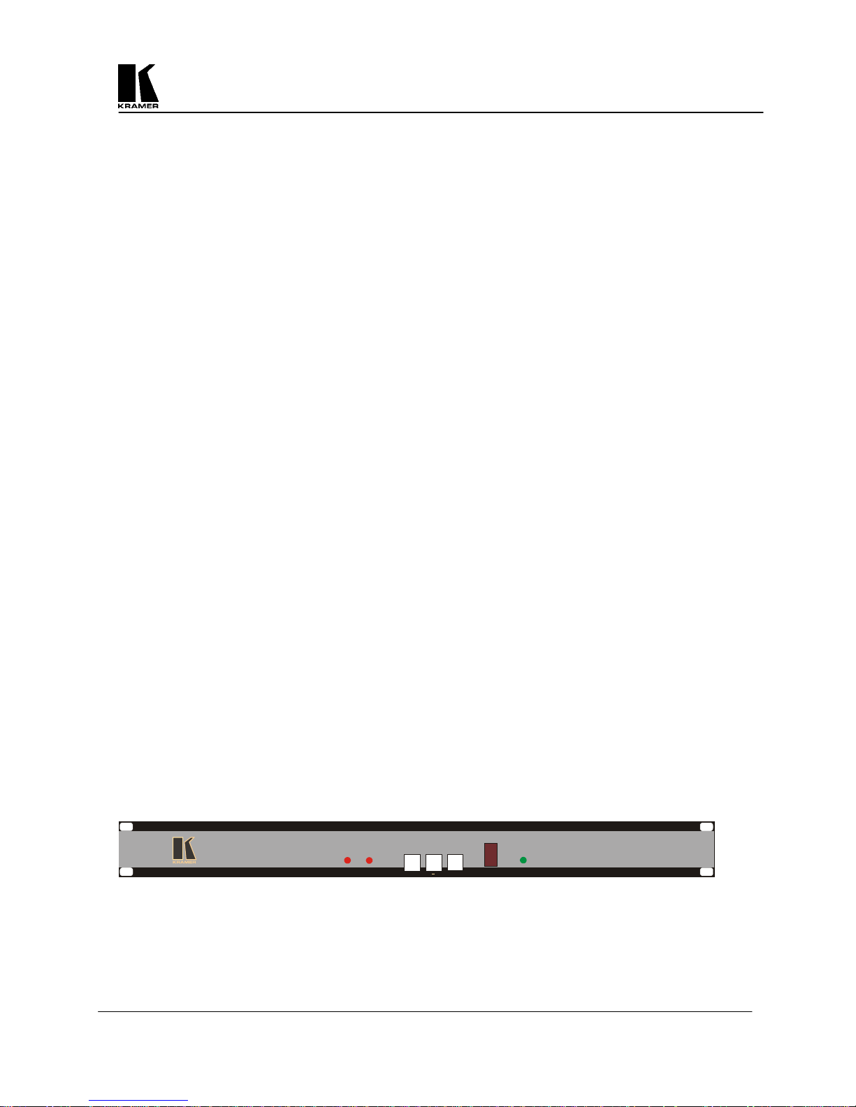
5.1 Rack Mounting the VP-702SC and VP-703SC
The VP-702SC and VP-703SC come equipped to mount in a standard 19” (1RU) EIA rack assembly. Neither
of these devices requires spacing above or below the unit for ventilation. Four standard rackmounting screws
are provided for each of the four corner holes in the rack ears.
IR
FREEZE
OS/US
MENU
FREEZE
Digital Scan Converter
OVERSCAN
+
POWER
VP-702SC
KRAMER ELECTRONICS, LTD.
5
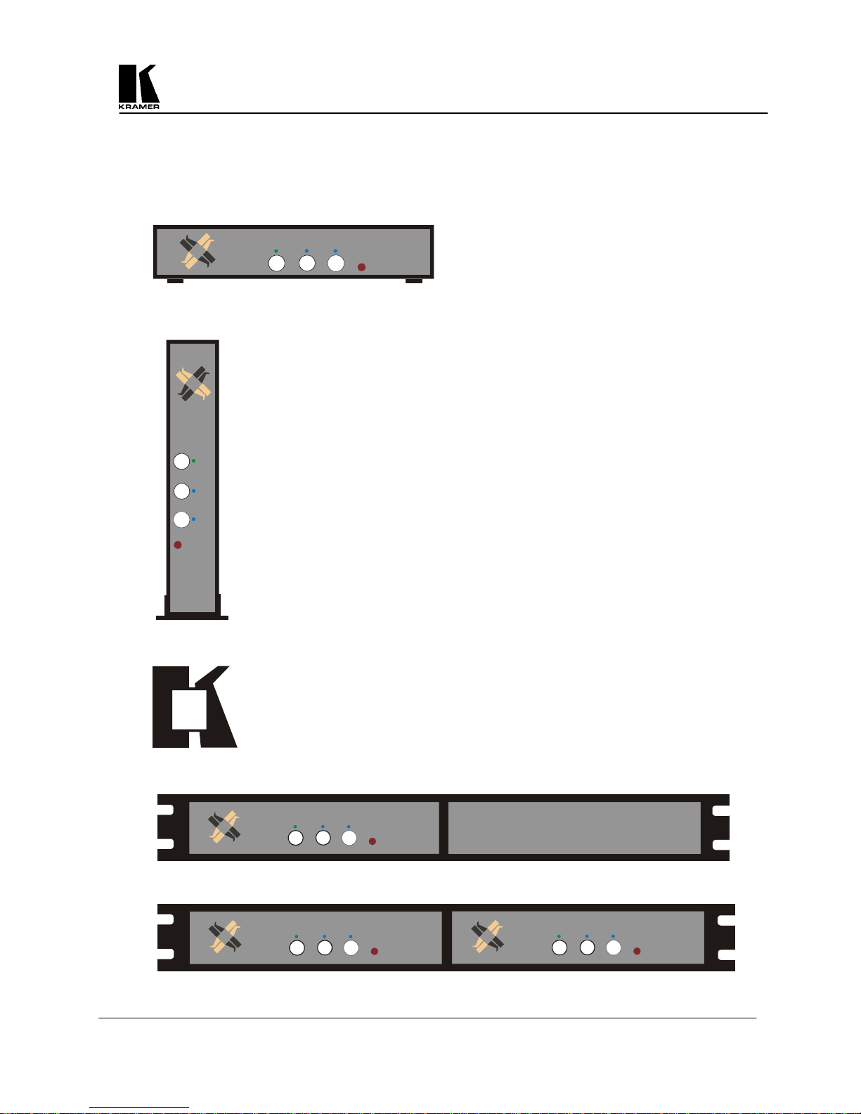
5.2 Mounting the VP-701SC
The VP-701SC is designed to provide maximum mounting flexibility. It may be mounted horizontally or vertically on a
desktop or in a single or dual 19” (1RU) EIA rack assembly with the optional Rackframe Unit.
+
ZE
OS/US -
E
E
R
F
IR
NU
ME
VP-701SC mounted Horizontally on the Desktop
MENU
C
1S
70
-
P
V
O
S
/U
S
-
F
R
E
EZ
E
+
IR
V
P
-70
1
S
C
VP-701SC mounted Vertically on the Desktop, using the “K” Base provided
“K” Base fits to the bottom of the VP-701SC for Vertical Desktop Mounting
+
-
U
N
E
M
VP-701SC in a Single Rackmount Configuration with the optional Rackframe Assembly
ZE
E
US
E
R
F
OS/
1SC
0
7
-
R
I
VP
Two VP-701SC units in a Dual Rackmount Configuration with the optional Rackframe Assembly
KRAMER ELECTRONICS, LTD.
+
-
U
N
E
M
OS/US
EEZE
FR
1SC
R
I
P-70
V
U
N
E
M
OS/US
+
ZE
FREE
1SC
70
-
R
I
VP
6
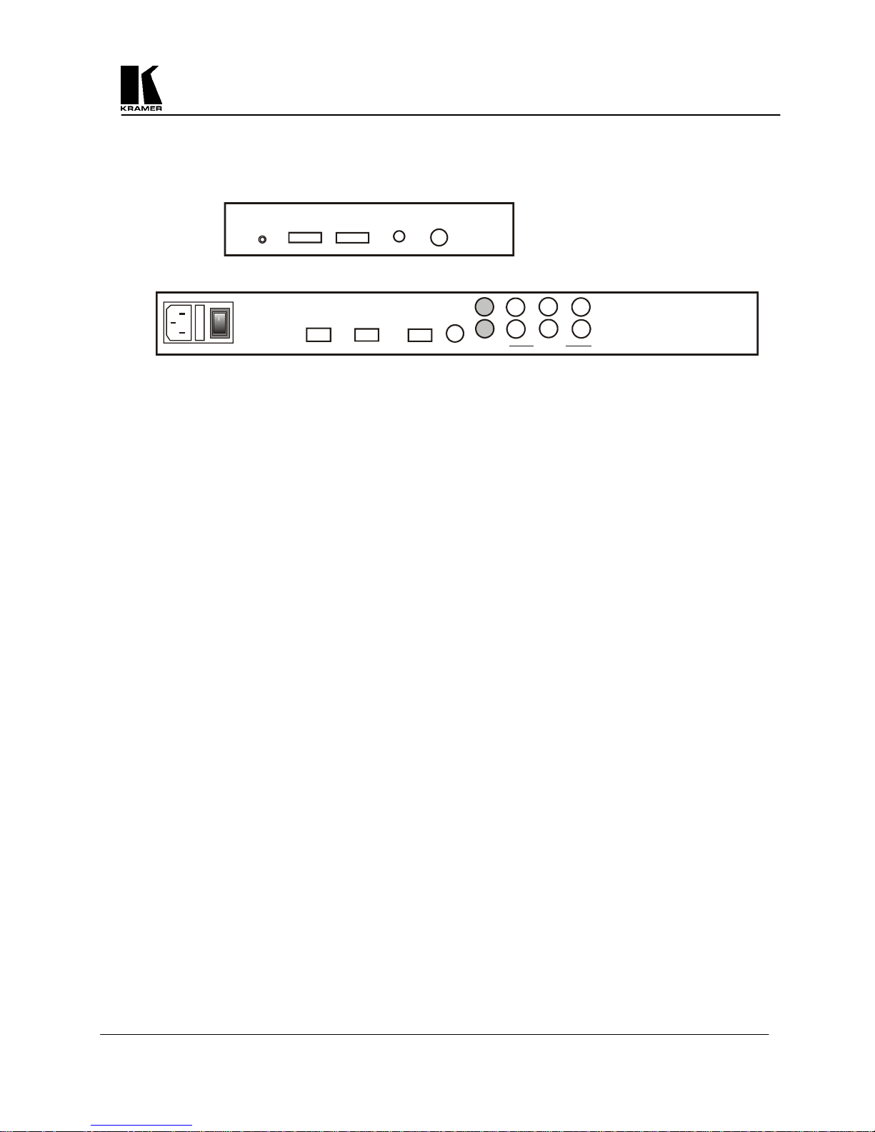
5.3 Connecting the Scan Converter to a Computer and Monitor
The first step is to connect the Scan Converter and related hardware. Below are rear panel drawings.
S-VIDEO
VP-701SC
+12VDC
PC IN
PC OUT
COMPOSITE
VP-702SC & VP-703SC
POWER
100-240V 50-60HZ
o
VGA INRS232
SV OUT OUTPUTSVGA OUT
G
R
CV
B
HS
VS
CS
Disconnect the computer monitor’s input cable from the computer’s VGA output connection. Connect this cable
to the 'VGA OUT' connector on the back of the Scan Converter. Macintosh computers that do not have an
HD15 type output connector may require an additional adapter. Next, use the VGA cable supplied to connect
the VGA output connection from the computer to the ‘VGA IN’ connector on the back of the Scan Converter.
After these connections are made and the computer and monitor are switched on, you will see the computer’s
output displayed on the computer monitor as before, even when there is no power to the Scan Converter.
5.4 Connecting the Video Outputs
The Scan Converter provides several different output types to allow connection to various video displays and
other equipment, such as TVs & VCRs. The choice of output type depends on what your equipment can accept.
Composite Video
on the back of the Scan Converter (the BNC connector marked CV) to the composite video input of your
target video equipment. Note that the VP-701SC’s output is an RCA connector marked Composite and a
BNC adapter is supplied for your convenience.
S-Video - use the S-Video cable provided to connect from the S-Video output on the back of the Scan
Converter to the S-Video input of your target video equipment. S-Video provides improved performance
over Composite Video.
RGB with Composite Sync - Use a 4xBNC to 4xBNC cable to link from the Red, Green, Blue, and
HS/CS outputs to the video display. The Scan Converter defaults to outputting negative-going CS
(Composite Sync) on the HS/CS connector, but if you encounter problems then it is likely that this has
been changed - see 'Advanced Features' later in this manual. Note that this output’s horizontal scan rate
is 15.75KHz and is not intended for connection to a computer monitor. Not available on the VP-701SC.
RGB with H&V Sync
VS outputs to the video display. Since the Scan Converter defaults to outputting CS (Composite Sync)
on the HS/CS and VS connectors, so you must see 'Advanced Features' later in this manual in order to
change this to the required separate H&V Syncs. It is recommended that another output be used, until
operation of the unit is understood. Not available on the VP-701SC.
- use the composite video cable provided to connect from the composite video output
- Use a 5xBNC to 5xBNC cable to link from the Red, Green, Blue, HS/CS and
5.5 Connecting the Serial Cable
The VP-702SC and VP-702SC Scan Converters can be controlled from a computer, and used as a remote
Microsoft® serial mouse emulator by connecting its RS-232 port to a computer's RS-232 port. See the section
on 'RS-232 Computer Control' later in this manual on how to use this control feature (RS-232 Control is the
default, and merely requires connecting a suitable RS-232 cable). Not available on the VP-701SC.
5.6 Connecting the AC Power
The VP-702SC and VP-703SC Scan Converters have internal power supplies and require the direct connection
of an AC input power source of 100-240VAC@50-60Hz. With the Power On/Off switch on the rear of the Scan
Converter in the Off position, plug the AC Cable supplied into the AC Receptacle on the back of the unit and
KRAMER ELECTRONICS, LTD.
7
plug the AC Cable into the power outlet. The VP-701SC requires a +12VDC input and comes with an external
power supply to provide that voltage, which requires connection to a 100-240VAC@50-60Hz power source.
5.7 Turning the Scan Converter On
Make sure that all cables are connected and that all other equipment is turned on - your computer monitor
should be functioning normally. The Scan Converter’s AC Power Switch on the rear panel should be switched
on. Note that there is no such power switch on the VP-701SC. When using a multi-purpose TV-Monitor, be
sure and select the correct line input (AUX or AV). The video monitor should now be displaying the same
picture as is on the computer monitor.
When the Scan Converter is switched on, the green LED indicator on the front panel will illuminate. If there is a
picture on the video monitor, but it is the wrong shape, position or color it may be necessary to alter some of the
status settings before a good picture is displayed. For example, it may be necessary to switch to PAL or NTSC
settings. Further details on selecting the correct settings for your displays follow in the Advanced Features
section. If there is no picture on the video monitor, then go to the Trouble Shooting section.
6 ABOUT THE SCAN CONVERTER
There are 3 ways to control the Scan Converter:
By the Infrared Remote Control unit.
By the Buttons on the Front Panel.
Directly from the computer via the RS-232 Serial Port (Not available on the VP-701SC).
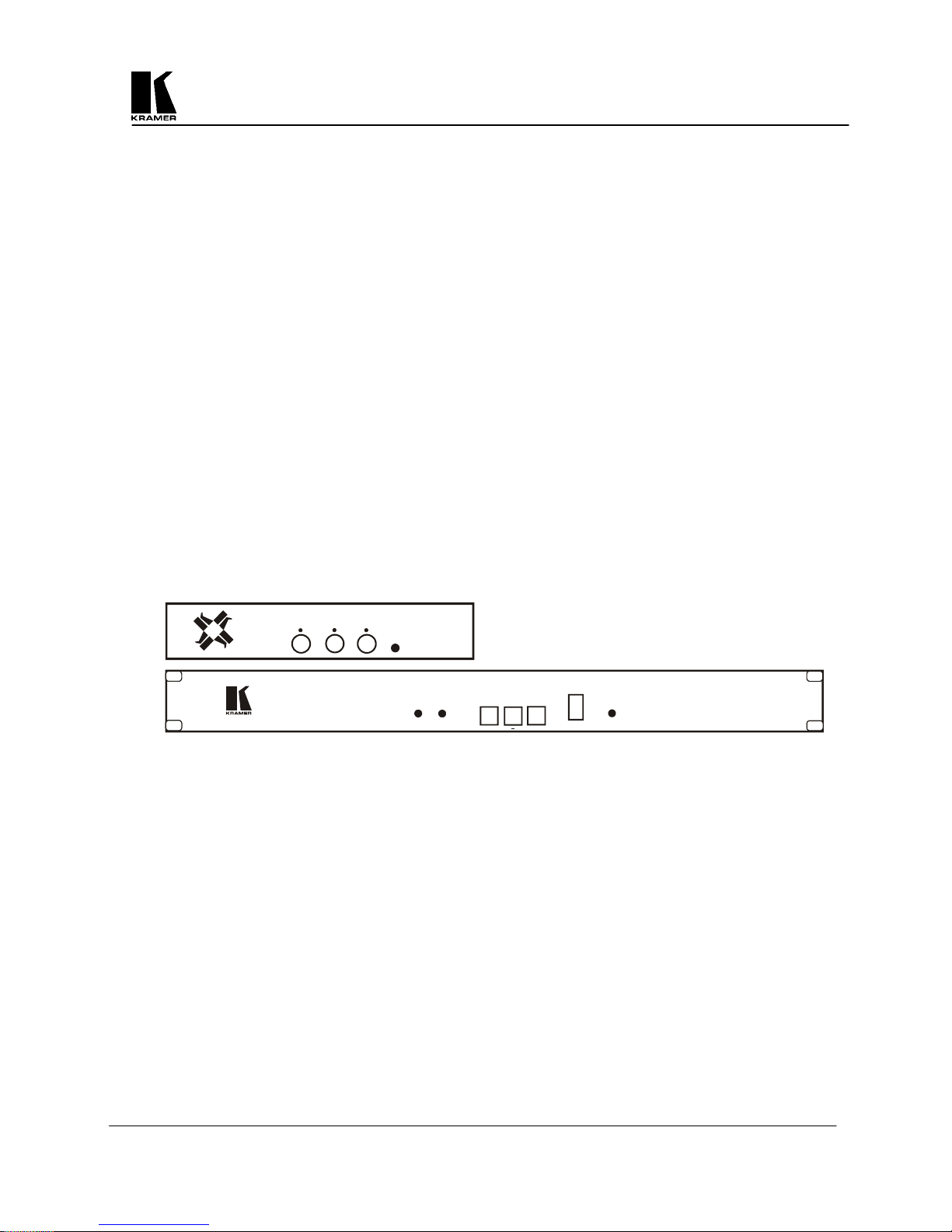
Each control method has its own section of this manual to describe the operation. Shown below are diagrams
that indicate the main features of the front panels of the VP-701SC and VP-702SC. The appearance of the VP703SC is identical to the VP-703SC. All three models operate in the same manner.
+
-
ZE
E
US
/
RE
F
OS
IR
OVERSCAN
V
Digital Scan Conv erter
U
MEN
6.1 Front Panel Buttons and LEDs
Power On LED – When the Scan Converter is powered up, the button labelled POWER will illuminate
green. It will flash if either the Menu Button or Remote Control Lock functions are enabled, as
described later in the manual. The VP-701SC does not have a separate Power LED.
Menu Button – Pressing this button will start the On-Screed Display (OSD) Setup or various functions,
which are described later.
OS/US LED
Mode. When in the Underscan Mode, this LED will not illuminate.
OS/US (-) Button – Pressing the OS/US (Overscan/Underscan) Button once places the unit in the
Overscan Mode and illuminates the OS/US LED. Pressing this button again returns the unit to the
Underscan Mode and extinguishes the LED. The OS/US Button mimics the remote control key of the
same name, and is described later in the manual. This button is also used to Decrease a value dispalyed
with the On-Screen Display.
Freeze LED – The Freeze LED will illuminate and flash when the Freeze Button is pressed to warn the
user that other controls are disabled.
Freeze (+) Button
Freeze LED. Pressing this button again returns the unit to the Normal Mode and extinguishes the LED.
The Freeze Button mimics the remote control key of the same name, and is described later in the manual.
This button is also used to increase a value displayed with the On-Screen Display.
– The OS/US (Overscan/Underscan) LED will illuminate when the unit is in the Overscan
– Presing the Freeze Button places the unit in the Freeze Mode and illuminates the
P-
70
FREEZE
1S
C
MENU
OS/US
FREEZE
IR
POWER
+
VP-702SC
KRAMER ELECTRONICS, LTD.
8

6.2 Special Button Usage on Power-up
Certain buttons can be held down when applying power to the unit, to perform certain functions:
Factory Reset – Hold down both the OS/US and Freeze Buttons when turning the unit on. This will
reset the unit to Factory Settings (and set the unit into NTSC video mode). It should only be used if the
unit's settings give an invalid output that the user cannot exit from, as all user-settings will be lost.
use this procedure as a last resort.
Set to NTSC Mode – This is done by holding the OS/US Button down when turning on the unit. This
changes the non-volatile PAL/NTSC setting to NTSC, and will be remembered even when power is off.
Set to PAL Mode – This is done by holding the Freeze Button down when turning on the unit. This
changes the non-volatile PAL/NTSC setting to PAL, and will be remembered even when power is off.
7 CONTROL AND SETUP USING THE INFRARED REMOTE CONTROL
7.1 Introduction
By now you should have the Scan Converter powered up and working with your computer and video monitor. If
you don't get an image on your video monitor, please refer to the Troubleshooting section at the back of this
manual.
This Scan Converter has been designed for ease of use, and you should find most of the controls simple to
understand and apply. Some features, such as Brightness Control, require more than one button press on the
Remote Control Unit (SC-RM), but this has only been done to reduce the number of buttons required to operate
the unit.
If at any time you find that the Remote Control or Front Panel Buttons are not working, then you may have
inadvertently pressed the LOCK Button on the Remote Control Unit. The continual flashing of the Power LED
on the Front Panel indicates the Lock Mode. A description of how to turn this feature on and off is provided
later in this manual.
This section of the manual covers:
All the Infrared Remote Control features of the Scan Converter.
Setup and adjustments for the unit and the effect they have on the final image.
Storing the settings so they are remembered by the unit the next time.
Therefore, the following is required reading!
Note
-
KRAMER ELECTRONICS, LTD.
9
 Loading...