

Page 1

KRAMER ELECTRONICS LTD.
USER MANUAL
MODEL:
VP-506
DVI/UXGA Scan Converter
P/N: 2900-300098 Rev 5
Page 2
Page 3

VP-506 – Contents
i
Contents
1 Introduction 1
2 Getting Started 2
2.1 Achieving the Best Performance 2
2.2 Safety Instructions 3
2.3 Recycling Kramer Products 3
3 Overview 4
3.1 Defining the VP-506 DVI/UXGA Scan Converter 5
4 Connecting the VP-506 6
5 Operating the VP-506 7
5.1 Using the Quick-Set Buttons 7
5.2 Adjusting the Display via the Menu Buttons 8
5.3 Using the Menu 8
5.4 Using Test Patterns 9
5.5 Saving and Recalling 10
6 Technical Specifications 12
Figures
Figure 1: VP-506 DVI/UXGA Scan Converter 5
Figure 2: Connecting the VP-506 DVI/UXGA Scan Converter 6
Figure 3: Overscanned and Underscanned images 8
Figure 4: Test Pattern Number 1 10
Page 4

VP-506 - Introduction
1
1 Introduction
Welcome to Kramer Electronics! Since 1981, Kramer Electronics has been
providing a world of unique, creative, and affordable solutions to the vast range of
problems that confront video, audio, presentation, and broadcasting professionals
on a daily basis. In recent years, we have redesigned and upgraded most of our
line, making the best even better!
Our 1,000-plus different models now appear in 11 groups that are clearly defined
by function: GROUP 1: Distribution Amplifiers; GROUP 2: Switchers and Routers;
GROUP 3: Control Systems; GROUP 4: Format/Standards Converters; GROUP 5:
Range Extenders and Repeaters; GROUP 6: Specialty AV Products; GROUP 7:
Scan Converters and Scalers; GROUP 8: Cables and Connectors; GROUP 9:
Room Connectivity; GROUP 10: Accessories and Rack Adapters and GROUP 11:
Sierra Video Products.
Congratulations on purchasing your Kramer VP-506 DVI/UXGA Scan Converter,
which is ideal for the following typical applications:
Multimedia, board rooms, and video conferencing
Any application where high-quality conversion of DVI data signals to video
signals is required
Page 5

2
VP-506 - Getting Started
2 Getting Started
We recommend that you:
Unpack the equipment carefully and save the original box and packaging
materials for possible future shipment
Review the contents of this user manual
Go to http://www.kramerelectronics.com/support/product_downloads.asp
to check for up-to-date user manuals, application programs, and to check if
firmware upgrades are available (where appropriate).
2.1 Achieving the Best Performance
To achieve the best performance:
Use only good quality connection cables (we recommend Kramer high-
performance, high-resolution cables) to avoid interference, deterioration in
signal quality due to poor matching, and elevated noise levels (often
associated with low quality cables)
Do not secure the cables in tight bundles or roll the slack into tight coils
Avoid interference from neighboring electrical appliances that may adversely
influence signal quality
Position your Kramer VP-506 away from moisture, excessive sunlight and
dust
This equipment is to be used only inside a building. It may only be
connected to other equipment that is installed inside a building.
i
!
Page 6

VP-506 - Getting Started
3
2.2 Safety Instructions
Caution:
There are no operator serviceable parts inside the unit
Warning:
Use only the Kramer Electronics input power wall
adapter that is provided with the unit
Warning:
Disconnect the power and unplug the unit from the wall
before installing
2.3 Recycling Kramer Products
The Waste Electrical and Electronic Equipment (WEEE) Directive 2002/96/EC
aims to reduce the amount of WEEE sent for disposal to landfill or incineration by
requiring it to be collected and recycled. To comply with the WEEE Directive,
Kramer Electronics has made arrangements with the European Advanced
Recycling Network (EARN) and will cover any costs of treatment, recycling and
recovery of waste Kramer Electronics branded equipment on arrival at the EARN
facility. For details of Kramer’s recycling arrangements in your particular country
go to our recycling pages at http://www.kramerelectronics.com/support/recycling/.
!
Page 7

4
VP-506 - Overview
3 Overview
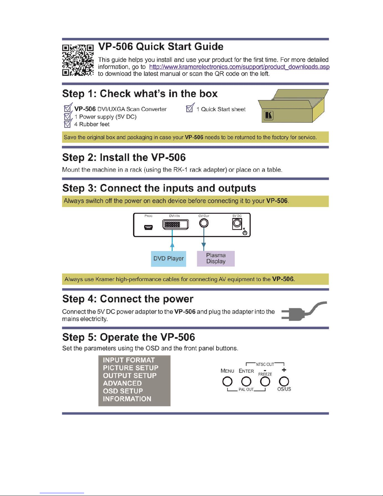
The Kramer VP-506 is a high-quality scan converter for down-scaling computer
graphics (VGA up to UXGA) to PAL or NTSC video. It supports VGA up to UXGA,
as well as the HD resolutions: 480p, 576p, 720p and 1080p.
The VP-506 features:
User-friendly front panel buttons for easy control of ProcAmp functions,
flicker-reduction, image optimization, one-touch freezing, overscanning and
underscanning
Memory locations to save and recall up to four setups, including picture
setup, input setup and output setup, zoom and advanced features
Brightness, contrast, saturation and flicker filter.
High-quality composite video
Selectable video standard (PAL or NTSC)
An external 5V DC source
Page 8
VP-506 - Overview
5
3.1 Defining the VP-506 DVI/UXGA Scan Converter
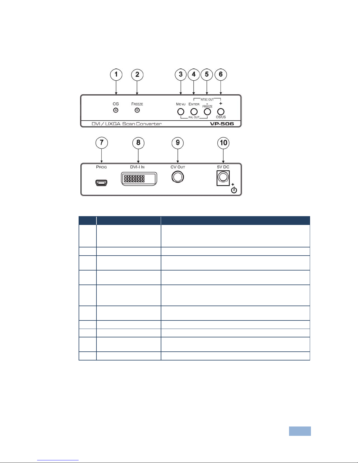
This section defines the VP-506.
Figure 1: VP-506 DVI/UXGA Scan Converter
#
Feature
Function
1
OS LED
Lights when the image is overscanned
The displayed image, when set correctly, is larger than the
screen
2
FREEZE LED
Lights when the FREEZE button is pressed
3
MENU Button
Press to enter/escape the on-screen display (OSD) menu.
Press together with the – button to reset to PAL output
4
ENTER / PAL OUT
Button
In OSD, press to choose the highlighted menu item.
Press together with the + button to reset to NTSC output
5
- / FREEZE/ NTSC
OUT Button
In OSD, press to move backward through the list or to
decrement the parameter value. When not in OSD, press
to freeze the display
6
+ / OS/US Button
Press + to scroll up the menu; press OS/US to toggle
between overscan and underscan
7
PROG USB Connector
Connects to a computer for upgrading the firmware
8
DVI IN Connector
Connects to the computer graphics source
9
CV OUT RCA
Connector
Connects to the composite video acceptor
10
5V DC
+5V DC connector for powering the unit
Page 9
6
VP-506 - Connecting the VP-506
4 Connecting the VP-506
Always switch off the power to each device before connecting it to your
VP-506. After connecting your VP-506, connect its power and then
switch on the power to each device.
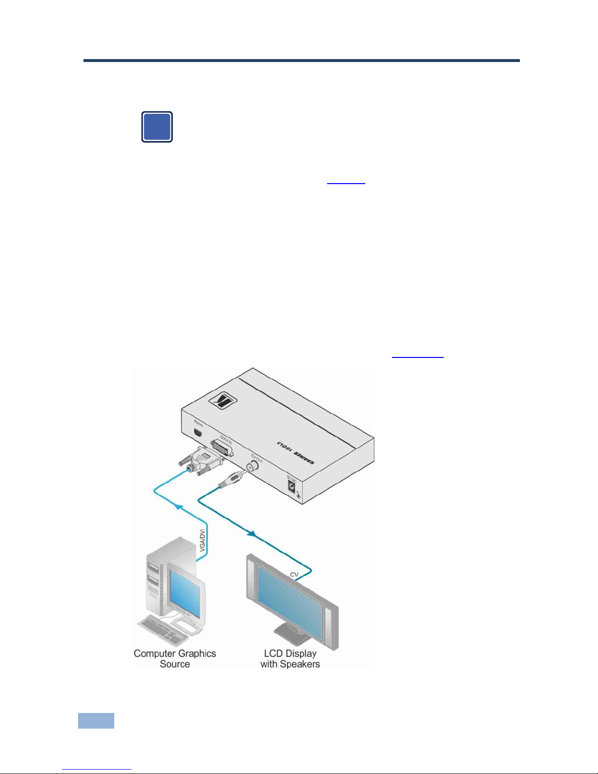
To connect your VP-506 as the example in Figure 2 illustrates, do the following:
1. Connect a DVI or VGA source to the DVI-I IN connector (for example, a PC
graphics card).
2. Connect the CV OUT RCA connector to the CV acceptor (for example, an
LCD display with speakers).
3. Connect the 5V DC power adapter to the power socket and connect the
adapter to the mains electricity.
4. Adjust the scan converter features if required (see Section 5.3).
Figure 2: Connecting the VP-506 DVI/UXGA Scan Converter
i
Page 10

VP-506 - Operating the VP-506
7
5 Operating the VP-506
You can operate your VP-506 via the front panel buttons, which are dual-purpose
buttons (except for the MENU button) that function as:
Quick-set buttons: FREEZE and OS/US; or
Menu buttons: MENU, ENTER, – and +
This section describes how to:
Use the quick set buttons (see Section 5.1)
Use the set of menu buttons (see Section 5.2)
Use the Menu screen (see Section 5.3)
Use the test patterns (see Section 5.4)
Save and recall (see Section 5.5)
5.1 Using the Quick-Set Buttons
The following sub-sections describe the VP-506 quick set buttons.
5.1.1 Using the FREEZE Button
Press the FREEZE button to freeze the picture on the screen. The frozen picture is
displayed regardless of the signal on the input to the unit. This allows you, for example,
to change the programs on the PC, and set up the next image.
By pressing the FREEZE button again, the frozen image will be replaced by the
most current image on the input to the unit.
5.1.2 Using the OS/US Button
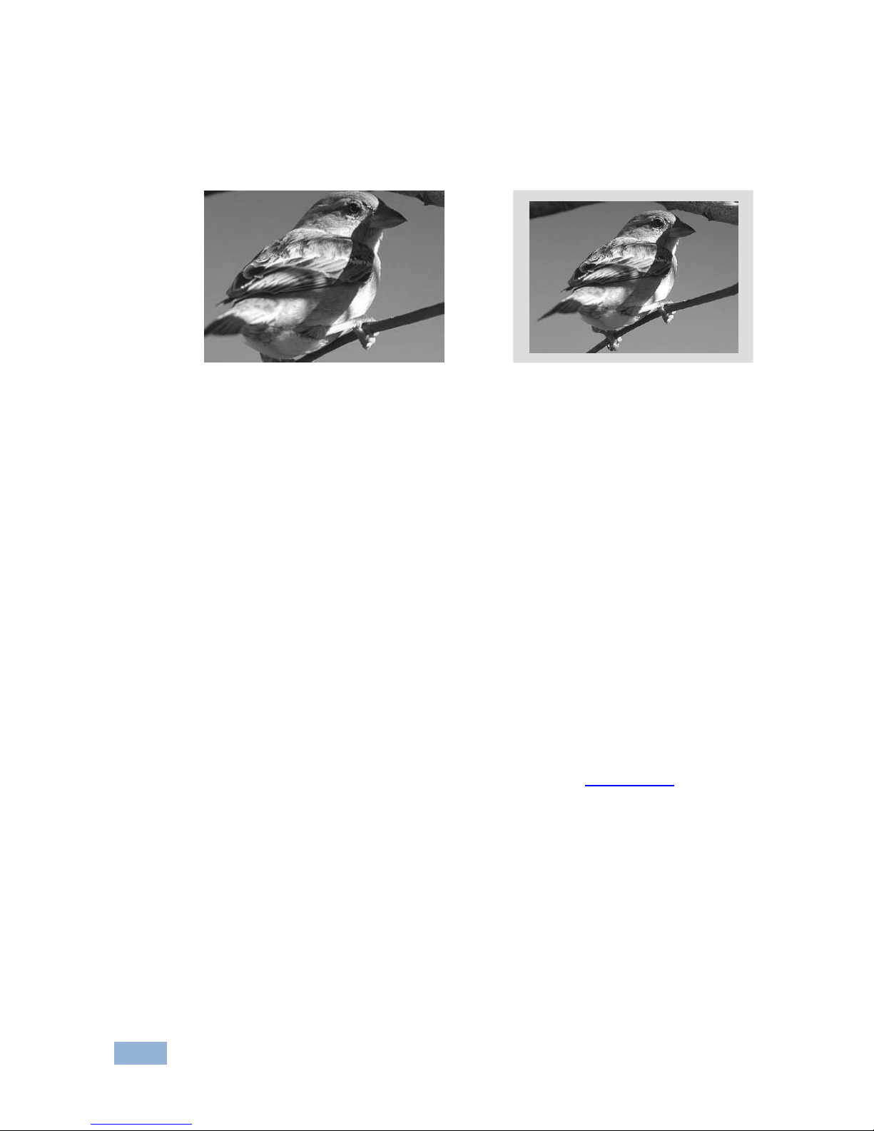
Press the OS/US button to toggle between overscan and underscan:
Overscan generally has no border and the displayed image is usually larger
than the screen
This makes the data bigger and easier to read with the possibility of having some of it
run off the edge of the screen.
Page 11
8
VP-506 - Operating the VP-506
Underscan (sometimes know as compress mode) generally leaves a border
around the image
The image appears reduced in size with a margin around it so that none of the data
gets lost.
Overscan
Underscan
Figure 3: Overscanned and Underscanned images
5.2 Adjusting the Display via the Menu Buttons
The menu buttons (MENU, ENTER, and +) let you adjust the screen settings.
Use the menu buttons as follows:
Press the MENU button to display the menu on the screen
Pressing the MENU button disables the quick-set buttons (FREEZE and OS/US)
Press the MENU button again each time you want to return to the previous
menu level or exit the menu
Press the + or - buttons to move up or down the menu respectively
Press ENTER to accept changes
Before exiting the menu, you can save settings (see Section 5.5.1)
5.3 Using the Menu
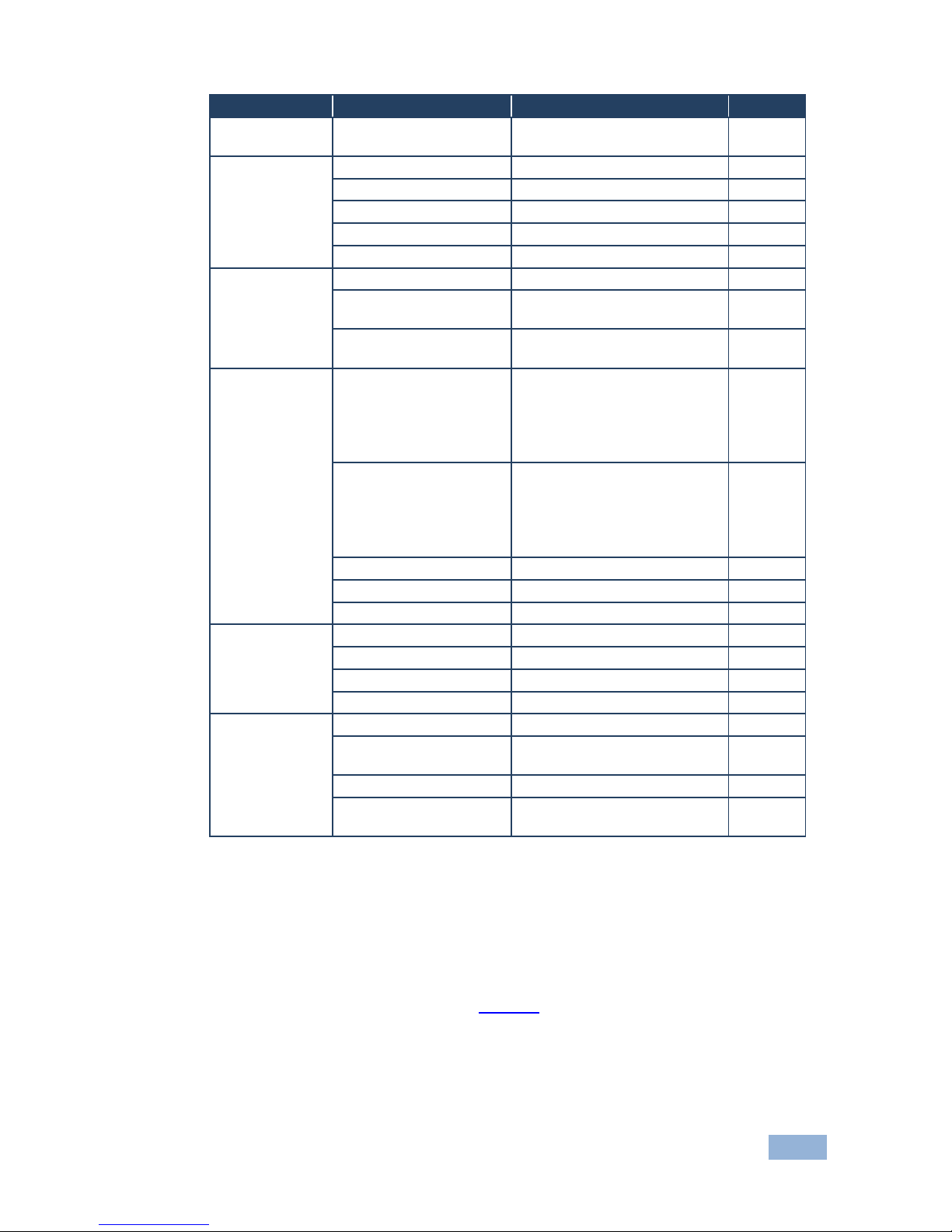
Using the main menu, you can adjust the screen display (screen adjustments
apply to both CV and Y/C displays). After pressing the MENU button (quick-set
buttons are disabled), the main Menu appears on the screen. Use the menu
buttons to scroll through the menu and make the required adjustments. The
following table defines the menu items.
The menu times-out after 20 seconds of inactivity.
Page 12
VP-506 - Operating the VP-506
9
Item
Selections
Parameter
Default
INPUT
FORMAT
DVI / PC / YPBPR
DVI
PICTURE
SETUP
CONTRAST
0-255
128
BRIGHTNESS
0-255
128
SATURATION
0-255
128
SHARPNESS
0-255
128
PHASE
0-31
16
OUTPUT
SETUP
H-POSITION
–50 to +50
0
V-POSITION
–29 to +29 (depends on timing
mode)
0
SIZE
100%, 90%, 95%, 105%,
110%, 115%
100%
ADVANCED
TEST_PATTERN
OFF,WHITE,CROSS,CROSS
HATCH,COLOR BAR,
GRAY SCALE,WHITE
WINDOW, RED, GREEN,
BLUE
OFF
NO_INPUT
WHITE,CROSS,CROSS
HATCH,COLOR BAR,
GRAY SCALE,WHITE
WINDOW, RED, GREEN,
BLUE
BLUE
SAVE
0-3 0 RECALL
0-3 0 FACTORY_RESET
OSD SETUP
OSD_HPOSITION
0-100
15
OSD_VPOSITION
0-100
5
OSD_TIMEOUT
0-100
15
OSD_TRANSPARENCY
0-15
15
INFORMATION
SOURCE
DVI or PC or YPbPr
TIMING
Shows input resolution
(e.g.1024X768@60)
OUTPUT
NTSC or PAL
VERSION
Shows firmware version (e.g.
V1.01)
5.4 Using Test Patterns
The Advanced menu lets you select Test Patterns and Save and Recall setups.
The VP-506 stores nine test patterns. From the Advanced menu, you can select a test
pattern (from 1 to 7) to show on screen. Figure 4 shows test pattern number 1.
Page 13

10
VP-506 - Operating the VP-506
Figure 4: Test Pattern Number 1
You can also set a test pattern to appear on the screen when there is no input
connected to the VP-506. To do so, enter the Advanced menu, select No Input
and set a test pattern number. This test pattern will appear when there is no input
connected. For example, set No Input to 1 if you want test pattern 1 (as in Figure
4) to appear when there is no input connected to the unit.
5.5 Saving and Recalling
The VP-506 lets you save and recall up to four setups (from 0 to 3).
The Save mode stores all the menu settings in one of the Save setup numbers.
The Save mode saves the Picture setup, the TV Output setup, the VGA Input Setup, the Zoom
setup, and the advanced setup (test patterns)
Saving Through the Advanced Menu
To save setup 1, for example:
1. Adjust the Picture Setup, the VGA Input Setup, the TV Output Setup, the
Zoom and panning, and the No Input number.
2. In the Advanced menu, select Save and set to number 1.
3. Press ENTER.
The setup is saved.
When disconnecting the unit, the setup that was saved last is stored
and reappears when reconnecting the unit.
i
Page 14

VP-506 - Operating the VP-506
11
Consider the following sequence, for example:
A certain setup is saved to 1
A different setup is saved to 2
Setup 1 is recalled
The unit is disconnected
The unit is reconnected
Setup 2 appears (since it was saved last)
5.5.1 Saving When Exiting the Menu
Whenever a change in the setup is performed, you are prompted to save the
changes, be it recalling a different setup, or changing the Zoom mode:
The Save Setting item does not timeout, it remains until No or Yes is selected.
Select No to cancel setup changes
Select Yes to save setup changes.
Changes are saved to the setup number currently appearing next to the
Save item
Note that your setup is saved to one of the 4 setups and overwrites the previous setup
associated with this setup number.
5.5.2 Recalling a Setup
To recall a setup select Recall from the advanced menu and select the setup
number you want to recall.
Page 15
12
VP-506 - Technical Specifications
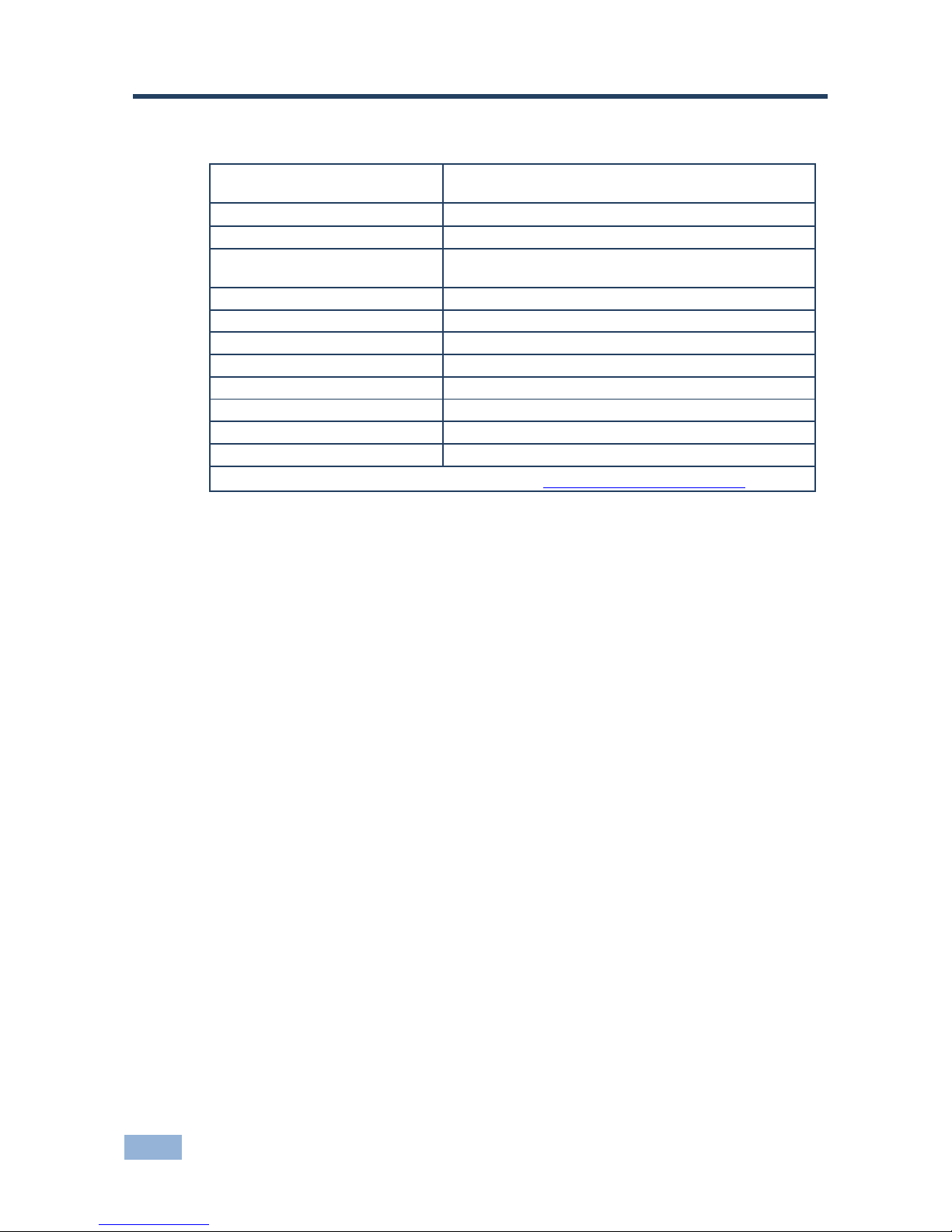
6 Technical Specifications
INPUT:
1 x DVI-I (DVI-D, VGA, YPbPr) on a 24-pin Molex
connector
OUTPUT:
1 composite video 1Vpp/75 on an RCA connector
INPUT RESOLUTIONS:
Up to WUXGA/1080p
CONTROLS:
Front panel and OSD: ProcAmp video controls, freeze,
underscan /overscan, 8 color bars
POWER CONSUMPTION:
5V DC, 540mA
OPERATING TEMPERATURE:
0° to +40°C (32° to 104°F)
STORAGE TEMPERATURE:
-40° to +70°C (-40° to 158°F)
HUMIDITY:
10% to 90%, RHL non-condensing
DIMENSIONS:
12cm x 7.5cm x 2.5cm (4.7" x 2.95" x 0.98") W, D, H
WEIGHT:
0.3kg (0.67lbs) approx
ACCESSORIES:
Power supply, mounting bracket
OPTIONS:
RK-1 19" rack adapter
Specifications are subject to change without notice at http://www.kramerelectronics.com
Page 16
Page 17
For the latest information on our products and a list of Kramer distributors,
visit our Web site where updates to this user manual may be found.
We welcome your questions, comments, and feedback.
Web site: www.kramerelectronics.com
E-mail: [email protected]
P/N:
2900-300098
Rev:
5
!
SAFE TY WARNI NG
Disconnect the unit from the power
supply before opening and servicing
 Loading...