


KRAMER ELECTRONICS LTD.
USER MANUAL
MODEL:
VP-4x8
4x8 VGA/UXGA Matrix
Switcher
P/N: 2900-000372 Rev 3

VP-4x8 – Contents i
Contents
1 Introduction 1
2 Getting Started 2
2.1 Achieving the Best Performance 2
2.2 Recycling Kramer Products 2
3 Overview 3
3.1 Defining the VP-4x8 4x8 VGA/UXGA Matrix Switcher 5
3.2 Using the IR Transmitter 7
4 Installing in a Rack 8
5 Connecting the VP-4x8 9
5.1 Connecting the VP-4x8 Rear Panel 9
5.2 Connecting the RS-232 Port to a PC or Controller 10
5.3 Connecting the RS-485 Port to a PC or Controller 11
5.4 Connecting the Ethernet Port 12
5.5 Setting the DIP-Switches 14
5.6 Cascading Machines 16
6 Operating the VP-4x8 18
6.1 Displaying Unit Characteristics 18
6.2 Confirming Settings 19
6.3 Storing/Recalling Input/Output Configurations 20
6.4 Locking the Front Panel 22
7 Technical Specifications 23
8 Serial Communication 24
8.1 Default Communication Parameters 24
8.2 Hex Code Table 24
9 Kramer Protocol 2000 25
Figures
Figure 1: UVP-4x8U 4x8 VGA/UXGA Matrix Switc her Front P anel 5
Figure 2: UVP-4x8U 4x8 VGA/UXGA Matrix Switcher Rear P anel 6
Figure 3: UVP-4x8U Underside View 7
Figure 4: Connecting the UVP-4x8U 4x8 VGA/UXGA Matrix Switcher 10
Figure 5: Crossed Cable RS-232 Connection 10
Figure 6: Straight Cable RS-232 Connection with a Null Modem Adapter 11
Figure 7: Local Area Connection Properties Window 13
Figure 8: Internet Protocol (TCP/IP) Properties Window 13
Figure 9: UVP-4x8U DIP-switches 14
Figure 10: Control Configuration via RS-232 and RS-485 17
Figure 11: Storing and Recalling using the Input/Output Buttons 20

VP-4x8 - Introduction 1
1 Introduction
Welcome to Kramer Electronics! Since 1981, Kramer Electronics has been
providing a world of unique, creative, and affordable solutions to the vast range of
problems that confront video, audio, presentation, and broadcasti ng professional s
on a daily basis. In recent years, we have redesigned and upgraded most of our
line, making the best even better!
Our 1,000-plus different models now appear in 11 groups that are clearly defined
by function: GROUP 1: Distributi on Amplif i ers; GROUP 2: Switchers and Routers;
GROUP 3: Control Systems; GROUP 4: Format/Standards Converters; GROUP 5:
Range Extenders and Repeaters; GROUP 6: Specialty AV Products; GROUP 7:
Scan Converters and Scalers; GROUP 8: Cables and Connectors; GROUP 9:
Room Connectivity; GROUP 10: Accessories and Rack Adapters and GROUP 11:
Sierra Products.
Congratulations on purchasing your Kramer VP-4x8 4x8 VGA/UXGA Matrix
Switcher, which is ideal for t he following typical appl ic at i ons:
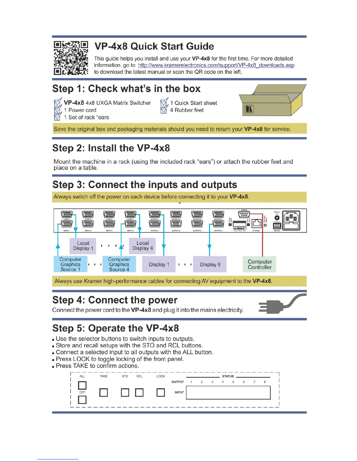
• Any professional display system requiring a true 4x8 computer graphics
matrix operation
• Multimedia and presentation source, and acceptor selection

2 VP-4x8 - Getting Started
2 Getting Started
We recommend that you:
• Unpack the equipment caref ul l y and save the original box and packaging
materials for possible future shipment
• Review the contents of this user manual
• Use Kramer high-performance, high-resolution cables
• Use only the power cord that is supplied with this machine
Go to http://www.kramerelectronics.com to check for up-to-date
user manuals, application programs, and to check if firmware
upgrades are available (where appropriate).
2.1 Achieving the Best Performance
To achieve the best performance:
• Use only good quality connection cables to avoid interference, deterioration
in signal quality due to poor matching, and elevated noise levels (often
associated with low quality cables)
• Do not secure the cables in tight bundles or roll the slack into tight coils
• Avoid interference from neighboring electrical appliances that may adversely
influence signal quality
• Position your Kramer VP-4x8 away from moisture, excessive sunlight and
dust
2.2 Recycling Kramer Products
The Waste Electrical and Electronic Equipment (WEEE) Directive 2002/96/EC
aims to reduce the amount of WEEE sent for disposal to landfill or incineration by
requiring it to be collected and recycled. To comply with the WEEE Directive,
Kramer Electronics has made arrangements with the European Advanced
Recycling Network (EARN) and will cover any costs of treatment, recycling and
recovery of waste Kramer Electronics branded equipment on arrival at the EARN
facility. For details of Kramer’s recycling arrangements in your particular c ountry
go to our recycling pages at
http://www.kramerelectronics.com/support/recycling/.
i

VP-4x8 - Overview 3
3 Overview
The VP-4x8 is a high-performance, high-resolution computer graphics video
switcher. The VP-4x8 lets you simultaneously route any or all of the four inputs to
any or all of the eight outputs and to loop each input to an additional output.
The VP-4x8 4x8 VGA/UXGA Matrix Switcher features:
• Video bandwidth of 400MHz that ensures transparent perform anc e even in
the most critical applications
• HDTV compatibility
• Looping inputs
• 12 preset memory locations for quick access to common configurati ons
• Delayed switching mode (ranging from 0 to 3.5 sec, in increments of 0.5sec)
for clean transitions (seamless switching) when switching between
non-genlocked sources
• DC coupled inputs and outputs
• Kr-isp™ advanced sync processing technology, which provides a sharp,
stable image when the sync level is too low, by restoring the sync signal
waveform
• A TAKE button that allows you to place multiple switches in a queue and
then activate them simultaneously with one touch of this button
• A LOCK button to prevent tampering with the front panel
• Automatic detection of c onnect ed input signals (respect i ve button
illuminates)
Control the VP-4x8 using the front panel buttons, or remotely via:
• RS-485 or RS-232 serial commands transmitted by a PC, touch screen
system, or other serial controller
• The Kramer infrared remote control transmitter
• Ethernet
• An external remote IR receiver (optional)

4 VP-4x8 - Overview
The VP-4x8 is a dependable and rugged unit that fits into one vertical space (1U)
of a standard 19-inch professional rack.
The RGBHV signals ar e connected on 15-pin HD pin connectors to reduce enclosure size.
VP-4x8 - Overview 5
VP-4x8 – Overview 5
3.1 Defining the VP-4x8 4x8 VGA/UXGA Matrix Switcher
This section defines the VP-4x8.
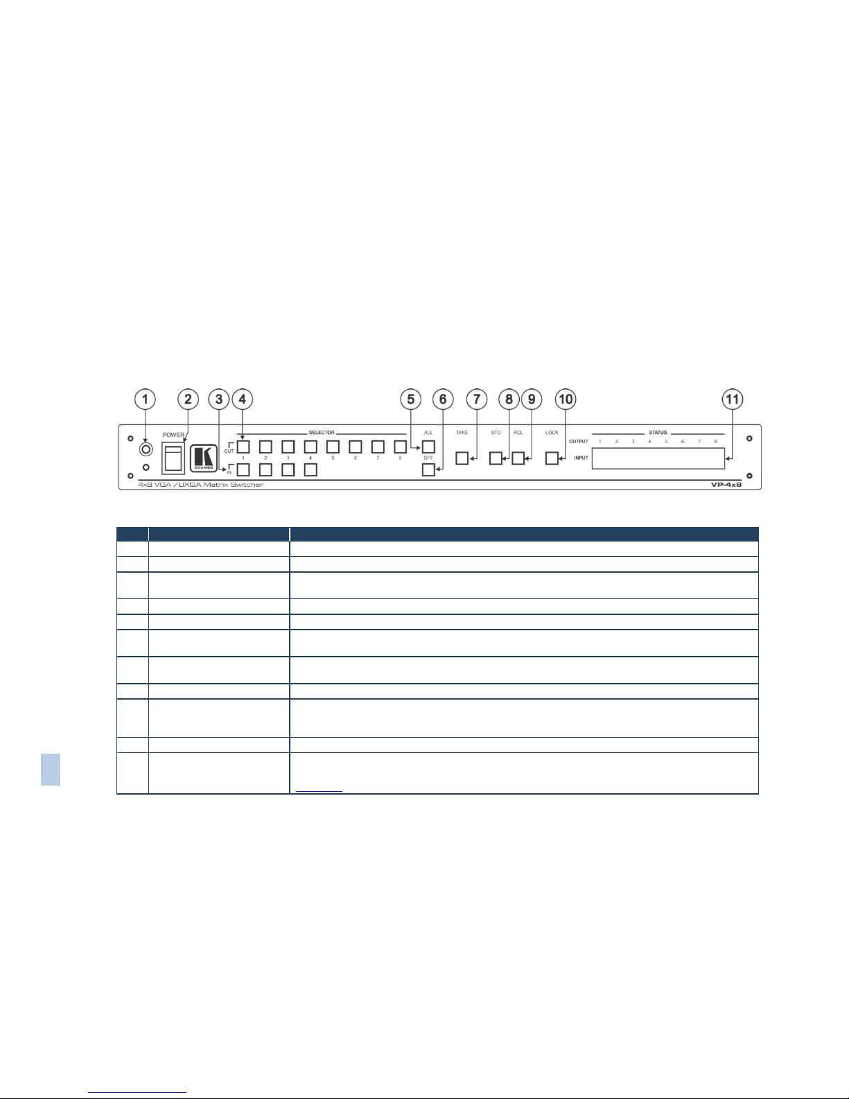
Figure 1: VP-4x8 4x8 VGA/UXGA Matrix Switcher Front Panel
# Feature Function
1 IR Receiver The red LED is illuminated when receiving signals from the infrared remote control transmitter
2 POWER Switch Illuminated switch for turning the unit ON or OFF
3 IN SELECTOR Buttons Select the input to switch to the output.
When a signal is detected, the input button illuminates in green
4 OUT SELECTOR Buttons Select the output to which the input is switched
5 ALL Button Pressing ALL followed by an INPUT button, connects that input to all outputs
6 OFF Button Press an OUT SELECTOR button and then an OFF button to disconnect that output from the inputs
Press the ALL button and then the OFF button to disconnect all the outputs
7 TAKE Button Pressing TAKE toggles the mode between the Confirm mode (in the Confirm mode, the TAKE button
illuminates) and the At Once mode (user confirmation per action is unnecessary)
8 STO (Store) Button Pressing STO followed by an input/output button stores the current setting
9 RCL (Recall) Button Pressing the RCL button and the corresponding IN/OUT button recalls a setup from the non-volatile
memory. The stored status flashes. Pressing a different IN/OUT button lets you view another setup.
After making your choice, pr es sing the RCL button again implements the new status
10 LOCK Button Disengages the front panel switches
11 STATUS 7-segment Display Displays the selected input switched to the output (marked above each input)
Also displays the number of IN and OUT ports, the firmware version number, and the MACHINE #. See
Section
6.1
6 VP-4x8 - Overview
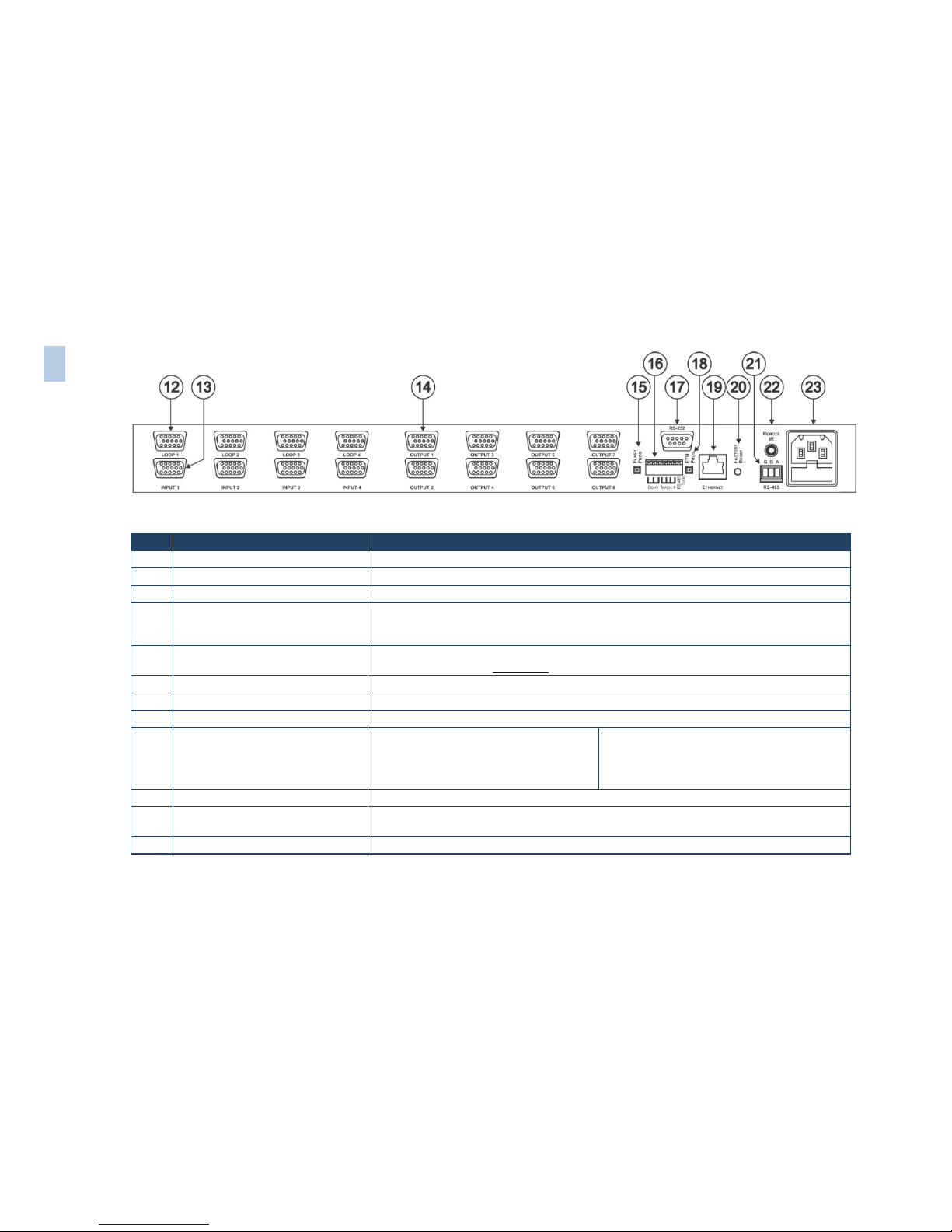
Figure 2: VP-4x8 4x8 VGA/UXGA Matrix Switcher Rear Panel
#
Feature
Function
12 LOOP 15-pin HD (F) Connectors Connect looped input to output acceptor (1 to 4)
13 INPUT 15-pin HD (F) Connectors Connect to the video sources (from 1 to 4)
14 OUTPUT 15-pin HD (F) Connectors Connect to the output acceptor (from 1 to 8)
15 FLASH PROG Button Push in for “Program” to upgrade to the latest Kramer firmware (see separate firmware upgrade
guide), or release for Normal (the factory default). The FLA SH PROG “Reset” button is located
on the underside of the unit
16 DELAY,MACH# and RS-485 TERM
DIP-switches
DIP-switches to set delay (DIPs 1-3), set the machine # (DIPs 4-7) and terminate the RS-485
connection (DIP 8) (see Section
5.5)
17 RS-232 9-pin D-sub (F) Port Connects to the PC or remote controller
18 ETH PROG Button Push in to upgrade ETH firmware, release for normal operation
19 ETHERNET RJ-45 Connecto r Connects to the PC or other serial controller through computer networking
20 ETH Factory Reset Button Press to reset to factory default definitions:
IP number − 192.168.1.39
Mask – 255.255.255.0
Gateway – 192.168.1.1
First disconnect the power cord and then
connect it again while pressing the ETH Factory
Reset button. The unit will power up and load its
memory with the factory default definitions
21 RS-485 Terminal Block Port Pin G is for ground connection; pins B (-) and A (+) are for RS-485
22 REMOTE IR 3.5mm Mini Jack Connect to an external IR recei v er uni t for con troll i ng t h e machi ne v ia an IR re m ote cont rol le r
(instead of using the front panel IR receiver)
23 Power Connecto r wit h Fus e AC connector enabling power supply to the unit
6 VP-4x8 – Overview

VP-4x8 - Overview 7
Figure 3 illustrates the underside of the VP-4x8 unit.
Figure 3: VP-4x8 Underside View
Feature
Function
RESET FOR PROGRAM Button Press to reset unit prior to firmware upgrade (see
separate firm ware upg ra de guide)
3.2 Using the IR Transmitter
You can use the RC-IR3 IR transmitter to control the machine via the built-in IR
receiver on the front panel or, instead, via an optional external IR receiver (Model:
C-A35M/IRR-50). The external IR receiver can be located up to 15 meters away
from the machine. This distance can be extended to up to 60 meters when used
with three extension cables (Model: C-A35M/A35F-50).
Before using the external IR receiver, be sure to arrange for your Kramer dealer to
insert the internal IR connection cable (P/N: 505-70434010-S) with the 3.5mm
connector that fits into the REMOTE IR opening on the rear panel. Connect the
external IR receiver to the REMOTE IR 3.5mm connector.
 Loading...