

Page 1
USER MANUAL
MODEL:
VP-440H2
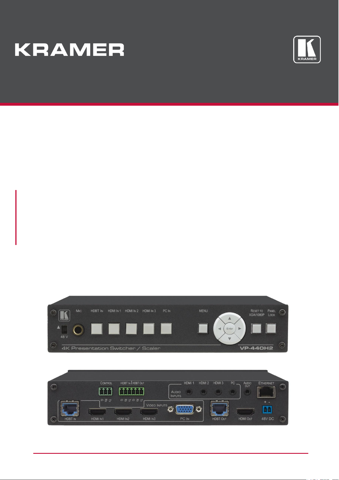
4K Presentation Switcher/Scaler
P/N: 2900-300644 Rev 2 www.KramerAV.com
Page 2

VP-440H2 – Introduction
i
Contents
Introduction 1
Getting Started 1
Overview 2
Typical Applications 3
Defining VP-440H2 4K Presentation Switcher/Scaler 4
Installing in a Rack 6
Connecting VP-440H2 7
Connecting to the VP-440H2 via RS-232 8
Microphone Pinout 8
Controlling External Devices via HDBT 9
Operating VP-440H2 10
Using the Front Panel Controls 10
Using the OSD Menu 11
Operating via Ethernet 15
Using the Embedded Web Pages 18
Technical Specifications 33
Input Resolutions 34
Output Resolutions 35
Default Communication Parameters 35
Protocol 3000 36
Understanding Protocol 3000 37
Kramer Protocol 3000 Syntax 37
Protocol 3000 Commands 39
Parameters 58
Video Resolutions 58
Page 3

Kramer Electronics Ltd.
VP-440H2 – Introduction
1
Go to www.kramerav.com/downloads/VP-440H2 to check for up-to-date user manuals,
application programs, and to check if firmware upgrades are available (where appropriate).
This equipment is to be used only inside a building. It may only be connected to other
equipment that is installed inside a building.
Introduction
Welcome to Kramer Electronics! Since 1981, Kramer Electronics has been providing a world of
unique, creative, and affordable solutions to the vast range of problems that confront the video,
audio, presentation, and broadcasting professional on a daily basis. In recent years, we have
redesigned and upgraded most of our line, making the best even better!
Our 1,000-plus different models now appear in 14 groups that are clearly defined by function:
GROUP 1: Distribution Amplifiers; GROUP 2: Switchers and Routers; GROUP 3: Control
Systems; GROUP 4: Format & Standards Converters; GROUP 5: Range Extenders &
Repeaters; GROUP 6: Specialty AV Products; GROUP 7: Scalers; GROUP 8: Cables and
Connectors; GROUP 9: Room Connectivity; GROUP 10: Mounting and Rack Adapters;
GROUP 11: Sierra Video; GROUP 12: Digital Signage; GROUP 13: Audio; GROUP 14:
Collaboration; and GROUP 15: KM & KVM Switches.
Getting Started
We recommend that you:
Unpack the equipment carefully and save the original box and packaging materials for
possible future shipment.
Review the contents of this user manual.
Achieving the Best Performance
Use only good quality connection cables (we recommend Kramer high-performance,
high-resolution cables) to avoid interference, deterioration in signal quality due to poor
matching, and elevated noise levels (often associated with low quality cables).
Do not secure the cables in tight bundles or roll the slack into tight coils.
Avoid interference from neighbouring electrical appliances that may adversely influence
signal quality.
Position your Kramer VP-440H2 away from moisture, excessive sunlight and dust.
Page 4

Kramer Electronics Ltd.
VP-440H2 – Introduction
2
Caution:
There are no operator serviceable parts inside the unit
Warning:
Use only the Kramer Electronics power supply that is provided with the unit
Warning:
Disconnect the power and unplug the unit from the wall before installing
For optimum range and performance using HDBaseT™, use recommended Kramer cables,
available at www.kramerav.com/product/VP-440H2.
Safety Instructions (DC)
Recycling Kramer Products
The Waste Electrical and Electronic Equipment (WEEE) Directive 2002/96/EC aims to reduce
the amount of WEEE sent for disposal to landfill or incineration by requiring it to be collected
and recycled. To comply with the WEEE Directive, Kramer Electronics has made
arrangements with the European Advanced Recycling Network (EARN) and will cover any
costs of treatment, recycling and recovery of waste Kramer Electronics branded equipment on
arrival at the EARN facility. For details of Kramer’s recycling arrangements in your particular
country go to our recycling pages at www.kramerav.com/support/recycling.
Overview
Congratulations on purchasing your Kramer VP-440H2 4K Presentation Switcher/Scaler.
VP-440H2 is a high−performance 4K@60Hz (4:4:4) presentation scaler/switcher with one
HDBaseT/POE, three HDMI and one computer graphics (VGA) inputs. The unit scales the
video, embeds the audio and outputs the signal to an HDMI output and an HDBaseT output
simultaneously. The unit includes analog and embedded audio inputs and outputs.
PixPerfect™ Scaling Technology – Kramer’s precision pixel mapping and high–quality
scaling technology.
HDTV Compatible.
HDCP Compliant.
HDBaseT Certified.
System Range – For the HDBT inputs and outputs, extended reach of up to 100m (330ft)
using Kramer recommended cables.
Supports Input PoE (Power over Ethernet) for powering the transmitter
Max. HDMI Resolution – 4K@60Hz (4:4:4).
Max. HDBaseT Resolutions – 4K@30Hz / 4K@60 (4:2:0)
Max. VGA Resolution – 1920 x 1200 @60Hz.
Multiple Aspect Ratio Selections – Full, best fit, overscan, underscan, letter box and
panscan.
Built–in ProcAmp – Color, hue, sharpness, noise, contrast and brightness.
Constant Output Sync – No output disruption while switching between inputs when no
video is detected.
Page 5

Kramer Electronics Ltd.
VP-440H2 – Introduction
3
For optimum range and performance use the recommended Kramer cables available
at www.kramerav.com/product/VP-440H2.
Auto Input Switching – Last connected & auto-scan, selectable.
Powerful Audio Features – Via DSP technology including audio equalization, mixing,
delay, etc.
Audio –With individual input and output level controls.
Audio embedding and de-embedding
Companion AFV (Audio-Follow-Video) – Stereo audio for HDMI and PC inputs, on 3.5mm
mini jacks.
Microphone Input – For mixing, switching or talk–over.
HDBaseT Tunnelling – Supports full HDBT tunnelling of Ethernet and RS–232 data.
Front Panel Lockout.
Non–Volatile Memory – Saves final settings.
Flexible Control Options – Front panel push buttons, RS–232, OSD (on–screen display)
menu with front panel navigation buttons, Ethernet with built–in Web pages.
Control your VP-440H2:
Directly, via the front panel push buttons
By RS-232 serial commands transmitted by a touch screen system, PC, or other serial
controller
Via the OSD (on-screen display)
Via the Ethernet with built-in Web pages
The VP-440H2 is housed in a 1/2 19" 1U enclosure, enabling 2 units to be rack mounted sideby-side in a 1U rack space with the optional RK-1 universal rack adapter.
Typical Applications
VP-440H2 is ideal for the following typical applications:
Educational – classrooms, lecture theaters
Projection systems in conference rooms, boardrooms, hotels and churches
Home theater up-scaling
Page 6
Kramer Electronics Ltd.
VP-440H2 – Defining VP-440H2 4K Presentation Switcher/Scaler
4
#
Feature
Function
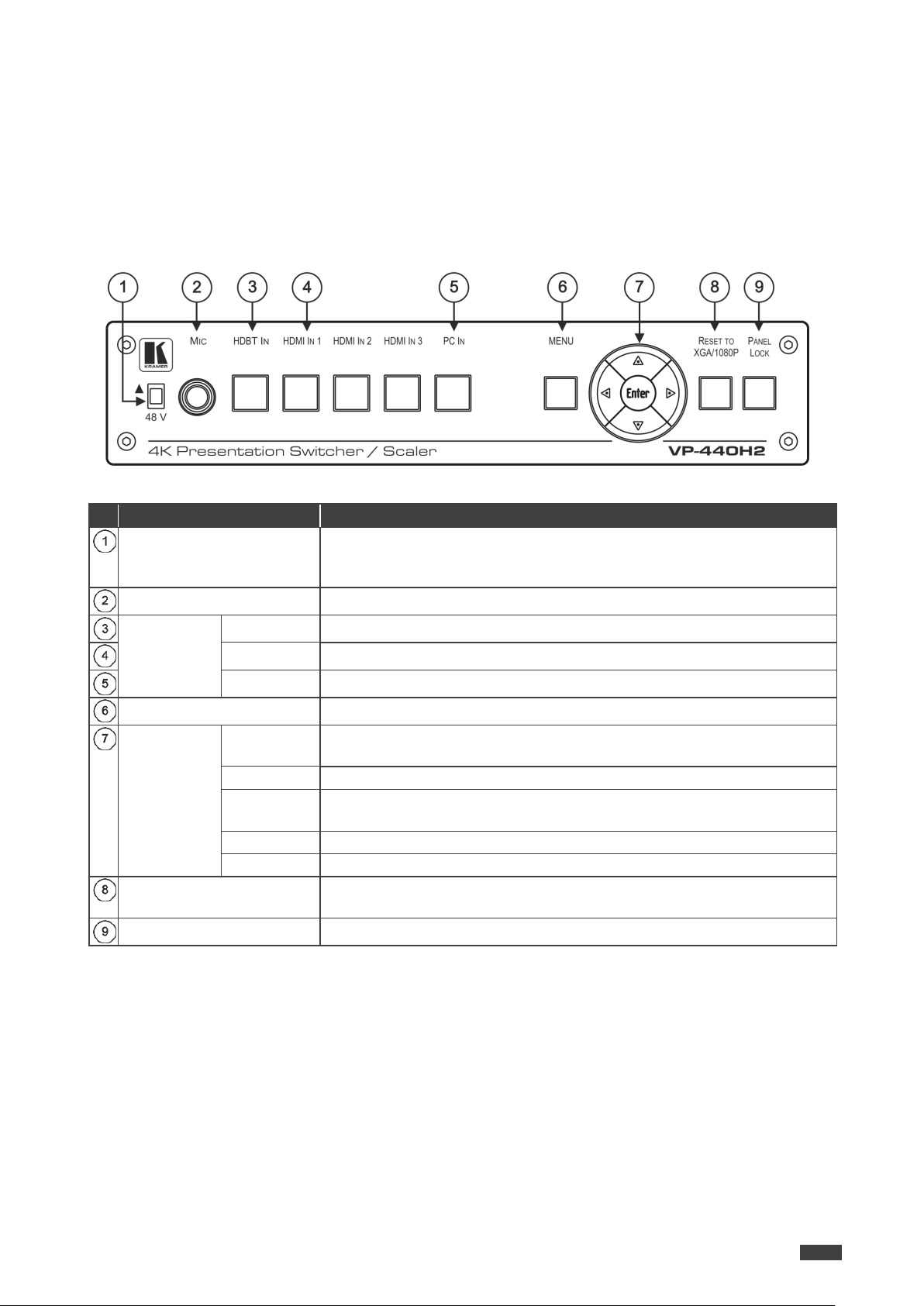
48 V () Slide Switch
Slide up (48V) to select a condenser type microphone; slide down to select a
dynamic type microphone (we recommend that you slide down if a microphone is
not connected to the VP-440H2).
MIC 6.3mm Jack
Connect to the microphone.
Input Selector
Buttons
HDBT IN
Press to select the HDBT input.
HDMI IN
Press to select the HDMI input (from 1 to 3).
PC IN
Press to select the computer graphics input.
MENU Button
Displays the OSD menu.
Navigation
Buttons
Press to decrease numerical values or select from several definitions.
When not in the OSD menu, press to reduce the output volume.
Press to move up the menu list values.
Press to increase numerical values or select from several definitions.
When not in the OSD menu, press to increase the output volume.
Press to move down the menu list.
ENTER
Press to accept changes and change the SETUP parameters.
RESET TO XGA/1080p
Button
Press and hold for about 5 seconds to toggle the output resolution between XGA
and 1080p, alternatively.
PANEL LOCK Button
Press and hold for about 5 seconds to lock/unlock the front panel buttons.
Defining VP-440H2 4K Presentation Switcher/Scaler
This section defines VP-440H2.
Figure 1: VP-440H2 4K Presentation Switcher/Scaler Front Panel
Page 7
Kramer Electronics Ltd.
VP-440H2 – Defining VP-440H2 4K Presentation Switcher/Scaler
5
#
Feature
Function
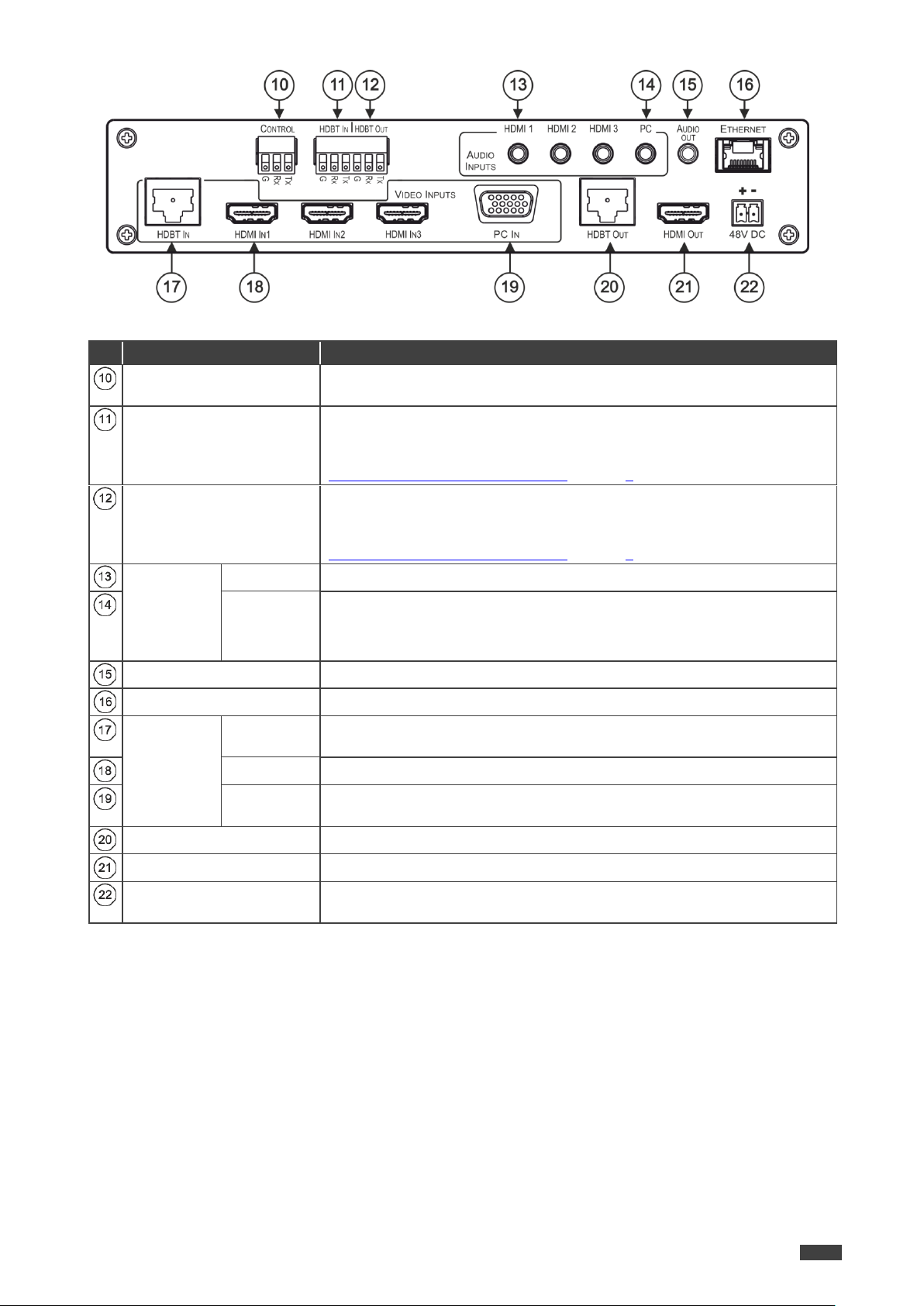
CONTROL (Tx, Rx, GND)
Terminal Block Connectors
Connect to the PC or the serial controller to control the device.
HDBT IN RS-232
Terminal Block Connectors
Connect to an RS-232 controller to control peripheral devices that are connected
to the HDBT transmitter (for example, a Blu-ray player connected to WP-20) or
connect to a device to control from a controller at the HDBT transmitter (see
Controlling External Devices via HDBT on page 9).
HDBT OUT RS-232
Terminal Block Connectors
Connect to an RS-232 controller to control peripheral devices that are connected
to the HDBT receiver (for example, a projector connected to TP-580Rxr) or
connect to a device to control from a controller at the HDBT receiver (see
Controlling External Devices via HDBT on page 9).
AUDIO
INPUT
Unbalanced
Stereo 3.5
Mini Jack
HDMI
Connect to the analog audio HDMI source (from 1 to 3).
PC
Connect to the analog audio computer graphics source.
AUDIO OUT 3.5 Mini Jack
Connect to an unbalanced stereo audio acceptor.
ETHERNET Connector
Connects to the PC or other controller through computer networking.
VIDEO
INPUT
Connectors
HDBT IN RJ45
Connect to an HDBT transmitter (for example, WP-20).
Can supply PoE (up to 13W) to the transmitter.
HDMI IN
Connect to the HDMI source (from 1 to 3).
PC IN on15pin HD
Connect to the computer graphics source.
HDBT OUT RJ-45 Connector
Connect to an HDBT receiver (for example, TP-580Rxr).
HDMI OUT Connector
Connect to the HDMI acceptor.
48V DC Power Terminal
Block
+48V DC connector for powering the unit.
Figure 2: VP-440H2 4K Presentation Switcher/Scaler Rear Panel
Page 8

Kramer Electronics Ltd.
VP-440H2 – Installing in a Rack
6
When installing on a 19" rack, avoid hazards by taking care that:
It is located within recommended environmental conditions. Operating ambient
temperature of a closed or multi-unit rack assembly may exceed ambient room
temperature.
Once rack mounted, there is enough air still flow around VP-440H2.
VP-440H2 is placed upright in the correct horizontal position.
You do not overload the circuit(s). When connecting VP-440H2 to the supply circuit,
overloading the circuits may have a detrimental effect on overcurrent protection and
supply wiring. Refer to the appropriate nameplate ratings for information. For example,
for fuse replacement, see the value printed on the product label.
VP-440H2 is earthed (grounded) and connected only to an electricity socket with
grounding. Pay particular attention when electricity is supplied indirectly (for example,
when the power cord is not plugged directly into the wall socket but to an extension
cable or power strip). Use only the supplied power cord.
To rack-mount VP-440H2:
Use an optional RK-T2B rack adapter.
Some models, may feature built-in rack ears:
Detachable rack ears can be removed for desktop use.
Always mount VP-440H2 in the rack before connecting any cables or power.
If you are using a Kramer rack adapter kit (for a machine that is not 19"), see the Rack
Adapters user manual for installation instructions available from our Web
www.kramerav.com/downloads/VP-440H2.
Installing in a Rack
This section provides instructions for rack mounting VP-440H2. Before installing in a rack,
verify that the environment is within the recommended range:
Operation temperature – 0 to 40C (32 to 104F).
Storage temperature – -40 to +70C (-40 to +158F).
Humidity – 10% to 90%, RHL non-condensing.
Page 9
VP-440H2 – Connecting VP-440H2
7
Always switch off the power to each device before connecting it to your VP-440H2. After
connecting your VP-440H2, connect its power and then switch on the power to each device.
Connecting VP-440H2
Kramer Electronics Ltd.
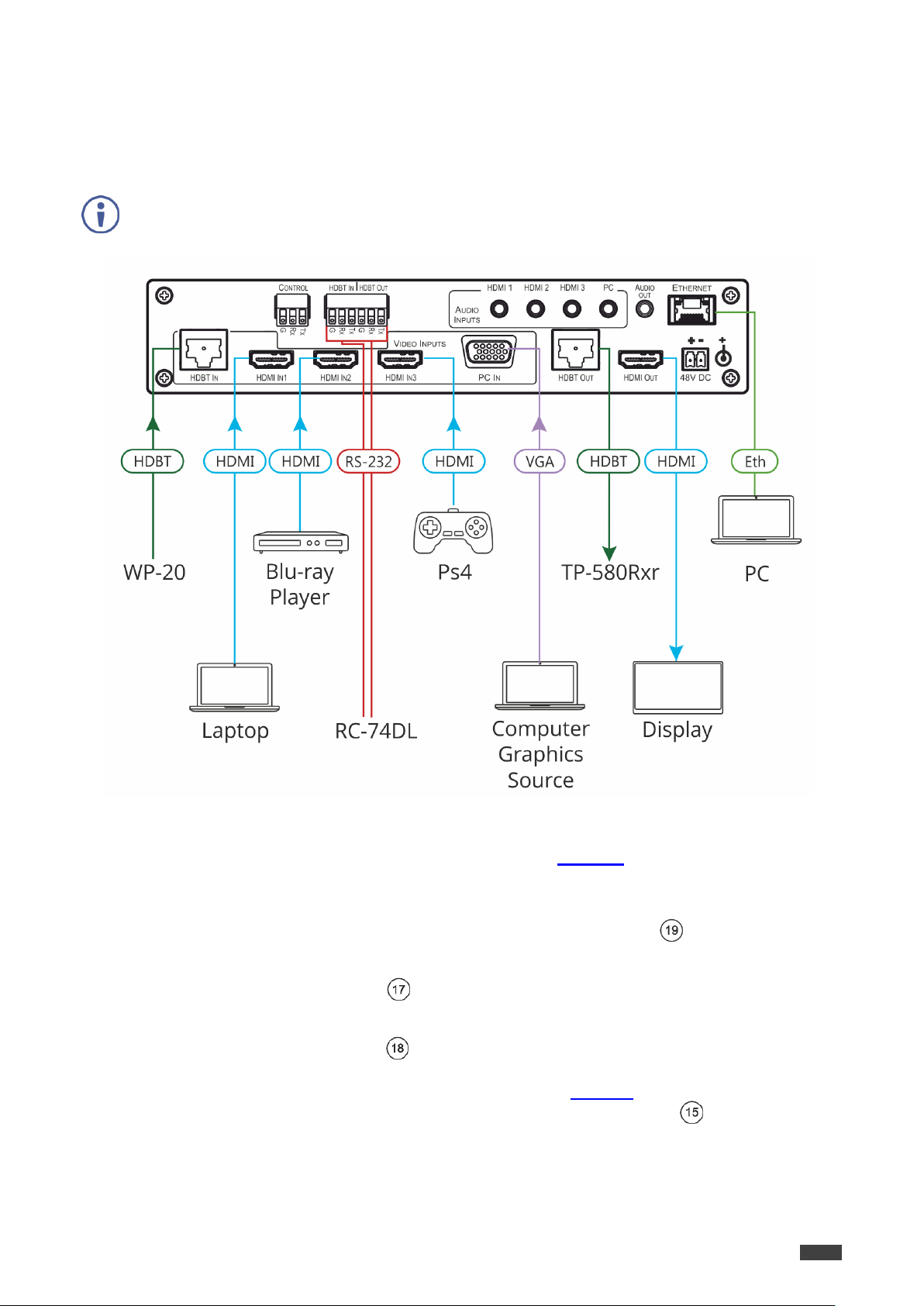
Figure 3: Connecting to the VP-440H2 Rear Panel
To connect VP-440H2 as illustrated in the example in Figure 3, do the following:
1. Connect the video sources
A computer graphics source to the PC IN 15-pin HD connector .
An HDBaseT transmitter (for example, Kramer WP-20 Wall Plate Transmitter) to the
HDBT IN RJ-45 connector .
HDMI sources (for example, a laptop, a blue-ray player, and a gaming console) to the
three HDMI IN connectors .
2. Connect an analog stereo audio source (not shown in Figure 3) for each of the three
HDMI inputs and for the PC input to the 3.5mm mini jack connectors .
Page 10

Kramer Electronics Ltd.
VP-440H2 – Connecting VP-440H2
8
Terminal Block PIN
9-pin D-sub PIN
Tx
PIN 2
Rx
PIN 3
GND
PIN 5
Microphone 6.3mm jack pinout for a
condenser microphone:
Figure 4: Condenser Microphone Pinout
Microphone 6.3mm jack pinout for a
Dynamic microphone:
Figure 5: Dynamic Microphone Pinout
3. Connect the video outputs:
An HDBaseT receiver (for example, Kramer TP-580Rxr) to the HDBT IN RJ-45
connector .
An HDMI acceptor to the HDMI OUT connector .
4. Connect an unbalanced stereo audio acceptor (for example, active speakers, not shown
in Figure 3) to the AUDIO OUT 3.5mm mini jack .
5. Connect a laptop to the Ethernet RJ-45 connector .
6. Connect an RS-232 controller (for example, Kramer RC-74DL) to the HDBT IN and
HDBT OUT terminal block connectors.
7. Connect the 48V power supply to the 48V DC power terminal block .
8. If required, connect a PC or serial controller (not shown in Figure 3) to the CONTROL
(Tx, Rx, G) terminal block connector, to control the unit via serial control .
Connecting to the VP-440H2 via RS-232
To control VP-440H2 via RS-232:
Connect the RS-232 Terminal block connector on VP-440H2 to the RS-232 9-pin D-sub
port on your PC/controlled device as shown in the PIN table below:
Microphone Pinout
Page 11
VP-440H2 – Connecting VP-440H2
9
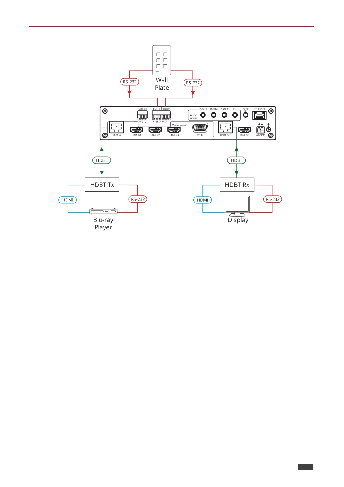
Controlling External Devices via HDBT
Kramer Electronics Ltd.
Figure 6: Controlling External Devices via HDBT
Page 12

VP-440H2 – Operating VP-440H2
10
Operating VP-440H2
VP-440H2 can be controlled using any of the following methods:
Front panel controls (see Using the Front Panel Controls on page 10)
OSD Menu, using the front panel buttons (see Using the OSD Menu on page 11)
Embedded web pages (see Using the Embedded Web Pages on page 18).
Protocol 3000 commands via RS-232 and / or TCP control (see Protocol 3000 Commands
on page 39).
Using the Front Panel Controls
Selecting the Input to be Switched to the Outputs
Kramer Electronics Ltd.
VP-440H2 enables selecting one of five inputs to be switched to the two outputs.
To select the input to be routed to the outputs:
Press the one of the input selector buttons , , or .
OR do one of the following:
Go to the Input Select page of the embedded web pages (see Selecting the Input to be
Switched to the Outputs on page 22).
Use the Protocol 3000 ROUTE command (see ROUTE on page 48).
Selecting the Microphone Type
To select the microphone type:
Move the 48 V button up to select a condenser type microphone or down to select a
dynamic type microphone.
We recommend keeping the switch down if a microphone is not connected to the VP-440H2.
Setting the Resolution to XGA/1080p
To set the resolution from the front panel:
Press the RESET TO XGA/1080p button to reset the video resolution to XGA or
1080p.
Press and hold the RESET TO XGA/1080p button for about 5 seconds to toggle
between switching to XGA or 1080p.
Page 13
Kramer Electronics Ltd.
VP-440H2 – Operating VP-440H2
11
If there is no button activity for the defined timeout period while within the OSD menu, the
menu disappears from the display.
Menu
Sub menu
Parameter
Parameters Description
Picture
CONTRAST
Set the contrast level.
BRIGHTNESS
Set the brightness level.
FINETUNE
(HDMI/HDBT)
HUE
Set these parameters for the HDMI and HDBT
inputs only.
SATURATION
SHARPNESS
NR (NOISE
REDUCTION)
FINETUNE (PC)
PHASE
Set these parameters for the PC input only.
CLOCK
H_POSITION
V_POSITION
COLOR
RED
Set the color levels.
GREEN
BLUE
Locking the Front Panel Buttons
The front panel buttons can be locked (disabled) to prevent unintentional button pressing.
To lock the front panel buttons:
Press and hold the Panel Lock button for about 5 seconds.
The Panel Lock button lights red and the front panel buttons are locked.
To unlock the front panel buttons:
Press and hold the Panel Lock button for about 5 seconds.
The Panel Lock button light goes out and the front panel buttons are unlocked.
Using the OSD Menu
The front panel navigation buttons enable you to control VP-440H2 via the OSD menu.
To use the OSD menu:
1. Press the MENU button to enter the menu.
The OSD menu appears on the video output display.
2. Use the navigation buttons :
Press the ENTER button to accept changes or to change the parameters.
Press the arrow buttons to move through the OSD menu.
3. On the OSD menu, select EXIT to exit the menu.
OSD Menus and Submenus
Page 14

Kramer Electronics Ltd.
VP-440H2 – Operating VP-440H2
12
Menu
Sub menu
Parameter
Parameters Description
Input
SOURCE
Select the input to be switched to the output.
Output
SIZE
Select the image size: FULL, OVERSCAN,
UNDER1, UNDER2, LETTERBOX, PANSCAN or
BEST FIT
4KIN > 4KOUT
Select BYPASS to avoid scaling when the input
resolution is 4K and the output is set to 4K.
Select SCALER to enable 4K to 4K scaling.
See 4K In to 4K Out Bypassing on page 14.
RESOLUTION
Select the required resolution for the output.
AUDIO
OUTPUT VOLUME
Set the volume for the outputs.
SOURCE
HDMI1
Select EMBEDDED for the embedded HDMI audio
ANALOG for the analog audio that corresponds to
the output, or AUTOMATIC.
HDMI2
HDMI3
SETTING
DELAY
Select the audio delay time, 40ms–200ms.
DRC (Dynamic
Range
Compression)
Set to ON to dynamically create a sound range
according to the volume level. For example, in a
movie, the volume is high enough to hear dialogue
and at the same time loud, sudden noises are toned
down.
BASS
Set the bass level.
TREBLE
Set the treble level.
LOUDNESS
Enable / disable the loudness function.
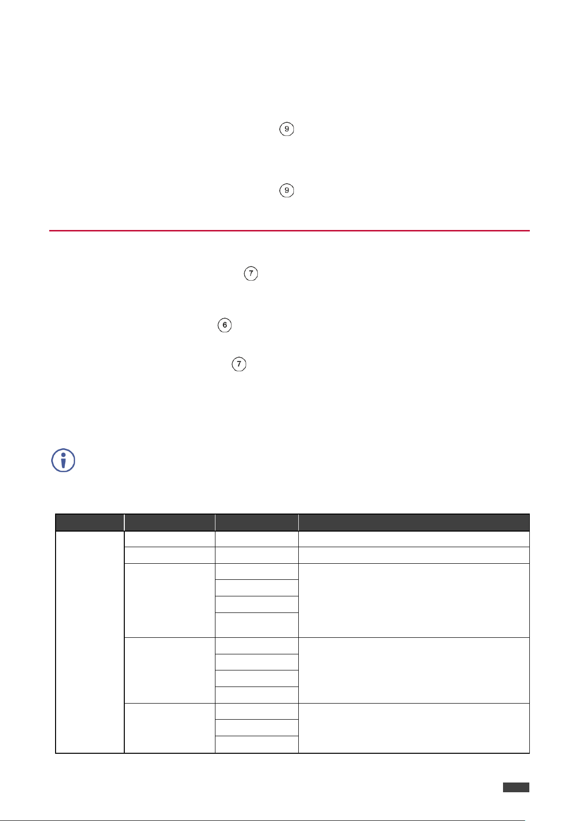
MIC SETTINGS
MIC MODE
Select the microphone mode from the following:
OFF / MIXER / TALKOVER / MIC ONLY.
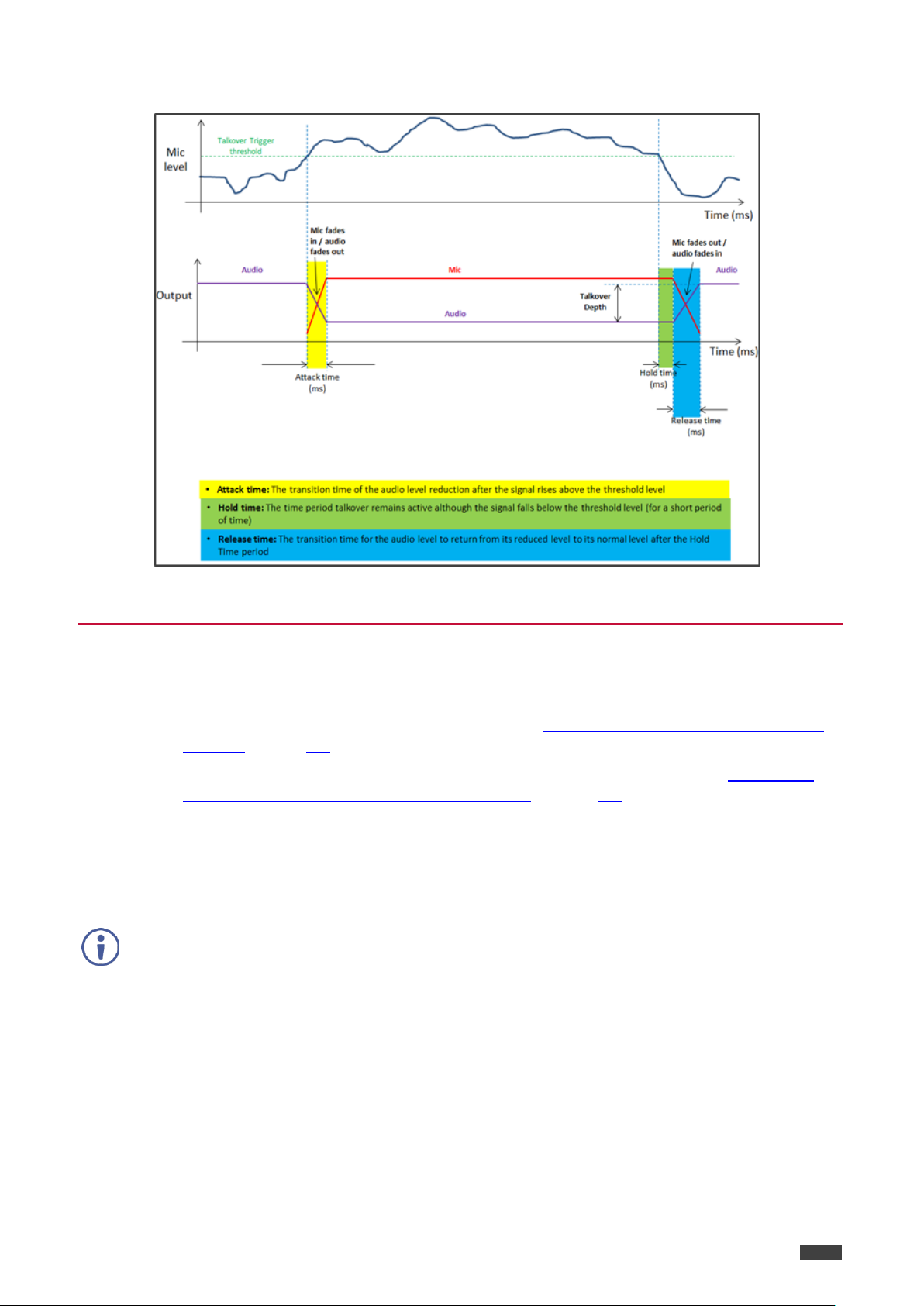
IN TALKOVER MIC MODE, SET THE FOLLOWING (see Microphone
Talkover on page 15 for details):
DEPTH
Set the decrease of the audio level during
microphone talkover.
TRIGGER
Set the microphone threshold level that triggers the
audio output-level decrease.
ATTACK TIME
Set the transition time of the audio level reduction
after the signal rises above the threshold level.
HOLD TIME
Set the time period that talkover remains active after
the signal falls below the threshold level.
RELEASE TIME
Set the transition time for the audio level to return
from its reduced level to its normal level after the
Hold Time period.
MIC VOLUME
MIC
Set the microphone input volume.
INPUT VOLUME
HDBT
Set the volume for each video input.
HDMI1
HDMI2
HDMI3
PC
MUTE
Mute the audio output.
Page 15
Kramer Electronics Ltd.
VP-440H2 – Operating VP-440H2
13
Menu
Sub menu
Parameter
Parameters Description
OSD
H POSITION
Adjust the OSD horizontal/vertical position on the
video display.
V POSITION
TIMER
Set the timeout for the OSD to disappear from the
display when not in use.
TRANSPARENCY
Set the OSD background between 100 (transparent)
and 0 (opaque).
DISPLAY
Select how information is shown on the display
during operation:
INFO: the information is shown for 10 seconds
ON: the information is shown constantly
OFF: the information is not shown
ADVANCED
HDCP ON INPUT
HDBT
Enable/disable HDCP for each of the inputs.
HDMI1
HDMI2
HDMI3
HDCP ON
OUTPUT
HDMI OUT
Enable/disable HDCP for each of the outputs.
HDBT OUT
AUTO-SYNC OFF
This feature shuts down VP-440H2 when there are
no active inputs. Select one of the following:
OFF – disable the AUTO SYNC OFF feature
FAST – shuts down after about 10 seconds
SLOW – shuts down after about 2 minutes
AUTO SWITCHING
Select one of the following to set the input with the
highest scan priority, to select “Last connected”
operation, or to disable auto switching:
Off: Disables auto switching
Scan from HDMI / HDBT / PC: Set auto-scanning,
and select from which input to begin the scanning
Last connected: When detecting that a source is
connected to an input (which previously had no
signal), automatically switch to that input
EDID MANAGE
HDMI 1 EDID
Set the EDID for each input.
HDMI 2 EDID
HDMI 3 EDID
HDBT EDID
PC EDID
ETHERNET
IP MODE
Set the IP mode to DHCP or Static.
STATIC IP
ADDRESS
Define the IP address.
SUBNET MASK
Define the Subnet Mask.
DEFAULT
GATEWAY
Define the Default Gateway.
CONTROL PORT
Enter the control port.
IP
View the IP address.
Page 16

Kramer Electronics Ltd.
VP-440H2 – Operating VP-440H2
14
Menu
Sub menu
Parameter
Parameters Description
MAC ADDRESS
View the MAC address.
INFO
SOURCE
View the selected video input.
INPUT
View the in input resolution.
OUTPUT HDMI
View the HDMI output resolution.
OUTPUT HDBT
View the HDBT output resolution.
VERSION:
Displays the FW version.
FACTORY
RESET
Resets all system settings to factory default and
erases any saved configurations.
SOFT RESET
Power cycles the unit.
BYPASS must be selected in order to support 4K HDR functionality.
Input Resolution
Selected Output
Resolution
Bypass Path
4K@24
4K@24
4K@25
4K@25
4K@30
4K@30
4K@50 4:4:4
4K@50 4:4:4
4K@50 4:4:4
4K@50 4:2:0
4K@50 4:2:0
4K@50 4:4:4
4K@60 4:4:4
4K@60 4:4:4
4K@60 4:4:4
4K@60 4:2:0
4K@60 4:2:0
4K@60 4:4:4
4K In to 4K Out Bypassing
VP-440H2 can upscale to any resolution (up to 4K), or downscale (from up to 4K) to any
resolution. Although the VP-440H2 enables “cross-scaling” (that is, scaling the output to the
same resolution as the input), this may result in picture quality deterioration – especially when
the output refresh rate is different to the input refresh rate.
To overcome the artifacts of 4K to 4K scaling:
In the OSD menu, select Output > 4K in->4K out > ByPass
–OR–
On the Output Settings page of the embedded web pages select 4Kin->4Kout >
ByPass.
When set to ByPass, all 4K resolutions can be processed to the same refresh rate without
scaling, and conversion from 4:4:4 to/from 4:2:0 color space can be performed.
The following table displays the resolutions that can be bypassed:
Page 17
VP-440H2 – Operating VP-440H2
15
This type of connection is recommended for identifying the VP-440H2 with the factory
configured default IP address.
Microphone Talkover
Kramer Electronics Ltd.
Figure 7: Microphone Talkover Mode
Operating via Ethernet
You can connect to the VP-440H2 via Ethernet using either of the following methods:
Directly to the PC using a crossover cable (see Connecting the Ethernet Port Directly
to a PC on page 15)
Via a network hub, switch, or router, using a straight-through cable (see Connecting
the Ethernet Port via a Network Hub or Switch on page 17)
Connecting the Ethernet Port Directly to a PC
You can connect the Ethernet port of the VP-440H2 directly to the Ethernet port on your PC
using a crossover cable with RJ-45 connectors.
After connecting the VP-440H2 to the Ethernet port, configure your PC as follows:
1. Click Start > Control Panel > Network and Sharing Center.
2. Click Change Adapter Settings.
3. Highlight the network adapter you want to use to connect to the device and click Change
settings of this connection.
Page 18
Kramer Electronics Ltd.
VP-440H2 – Operating VP-440H2
16
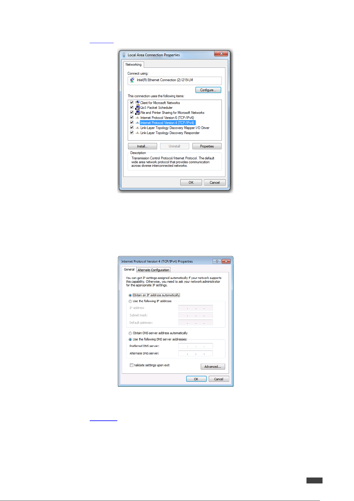
The Local Area Connection Properties window for the selected network adapter appears as
shown in Figure 8.
Figure 8: Local Area Connection Properties Window
4. Highlight Internet Protocol Version 4 (TCP/IPv4).
5. Click Properties.
The Internet Protocol Properties window relevant to your IT system appears.
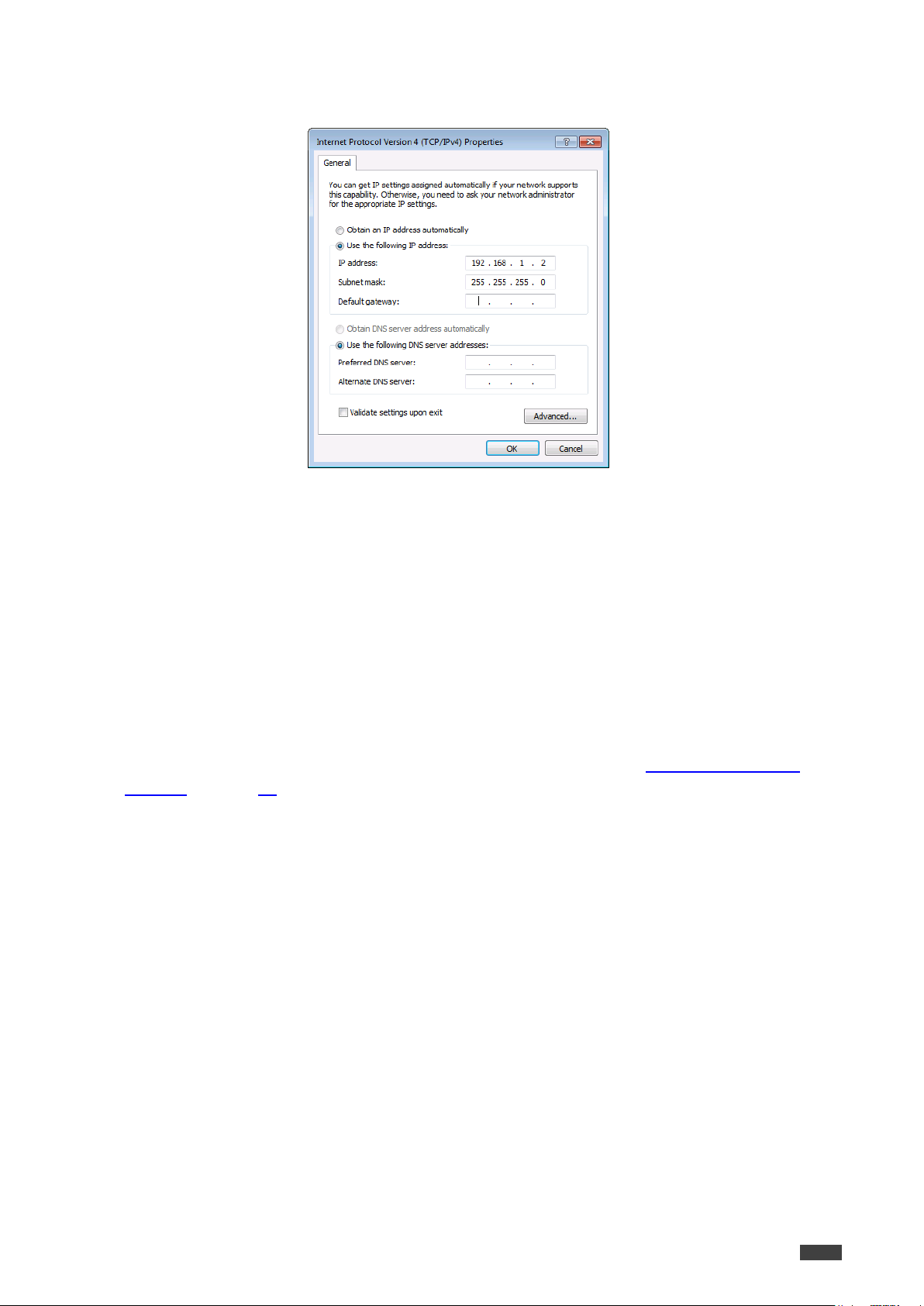
6. Select Use the following IP Address for static IP addressing and fill in the details as
shown in Figure 10.
Figure 9: Internet Protocol Version 4 Properties Window
Page 19
VP-440H2 – Operating VP-440H2
17
For TCP/IPv4 you can use any IP address in the range 192.168.1.1 to 192.168.1.255
(excluding 192.168.1.39) that is provided by your IT department.
Figure 10: Internet Protocol Properties Window
Kramer Electronics Ltd.
7. Click OK.
8. Click Close.
Connecting the Ethernet Port via a Network Hub or Switch
You can connect the Ethernet port of the VP-440H2 to the Ethernet port on a network hub or
using a straight-through cable with RJ-45 connectors.
Configuring the Ethernet Port
You can set the Ethernet parameters via the embedded Web pages (Configuring Network
Settings on page 23).
Page 20

Kramer Electronics Ltd.
VP-440H2 – Operating VP-440H2
18
Using the Embedded Web Pages
The web pages let you control the VP-440H2 via the Ethernet. They are accessed using a web
browser and an Ethernet connection.
Before attempting to connect, ensure that your browser is supported. See Technical
Specifications on page 33 for a list of supported browsers.
The VP-440H2 web pages enable performing the following:
Loading and Saving Configurations on page 19
Entering Standby Mode on page 20
Configuring Video Input Settings on page 21
Selecting the Input to be Switched to the Outputs on page 22
Freezing or Clearing the Video Output on page 22
Adjusting Microphone and Output Volume on page 22
Configuring Network Settings on page 23
Upgrading the Firmware on page 24
Configuring Video Output Settings on page 25
Configuring HDCP per Input/Output on page 27
Managing EDID on page 28
Adjusting Audio Input Settings on page 29
Adjusting Microphone Settings on page 30
Configuring Automatic Switching Settings on page 31
Defining Freeze Button on page 32
Page 21

Kramer Electronics Ltd.
VP-440H2 – Operating VP-440H2
19
To browse the VP-440H2 Web pages:
1. Open your Internet browser.
2. Type the IP number of the device in the address bar of your browser. For example, the
default IP number:
The Controller application page appears.
Figure 11: Controller Application Page with Navigation List on Left
3. Click the tabs on the left side of the screen to access the relevant web page.
Loading and Saving Configurations
VP-440H2 web pages enable you to save a configuration for easy recall in the future.
At the bottom left hand side of all web pages there is an Upload and a Save button. These
enable you to save the current configuration and load any pre-saved configurations.
To save the current configuration:
1. Configure the device as required.
2. Click Save.
The Save File window appears.
3. Browse to the required location to which to save the file.
4. Enter the required name for the saved preset.
Page 22

VP-440H2 – Operating VP-440H2
20
When using Chrome, the file is automatically saved in the Downloads folder.
5. Click OK.
The current configuration is saved.
To load a configuration:
1. Click Upload.
An Explorer window opens.
2. Select the required file and click Open.
The device is configured according to the saved preset.
Entering Standby Mode
Standby mode puts the device in a low power consumption mode without turning it off.
To toggle between standby mode and normal operation:
Click the power icon on the right-hand side of the web pages header.
When in standby mode, the icon appears dim:
Kramer Electronics Ltd.
Figure 12: The VP-440H2 Standby Mode
Page 23

Kramer Electronics Ltd.
VP-440H2 – Operating VP-440H2
21
If HDCP is disabled on an input, an HDCP encrypted source will not pass through the unit.
Configuring Video Input Settings
VP-440H2 web pages enable you to individually configure settings for each of the video inputs.
To configure video input settings:
1. Click Input Select on the left side of the web page (Figure 11).
The Input Select page appears.
Figure 13: Web Pages – Input Select Page
2. In the Video Switching area, click the edit icon on the right side of the relevant video
input.
The settings window appears for the selected input.
Figure 14: Setting Window for Input 1
3. If required, type a new name in the top field and click the save icon to change the name
of the input that appears in the web pages.
4. Click ON/OFF to enable/disable the HDCP decryption on the selected input.
Page 24

VP-440H2 – Operating VP-440H2
22
To define what happens when you press the Freeze button, see Defining Freeze Button on
page 32).
The microphone and output volume can also be adjusted from the Audio web page.
5. For Audio Source, select one of the following:
Automatic – the embedded audio on the HDMI input is selected for an HDMI signal, or
the analog audio input is selected if the input is not HDMI (for example, for a DVI input
signal)
Analog – the analog audio input is selected
Embedded – the embedded audio in the HDMI signal is selected
6. Adjust the audio volume for this input by typing a number in the box or using the slider
control.
7. Click the X to exit the input settings window.
Selecting the Input to be Switched to the Outputs
To select the input to be switched to the outputs using the web pages:
1. Click Input Select on the left side of the web page (Figure 11).
The Input Select page appears (Figure 13).
Kramer Electronics Ltd.
2. In the Video Switching area, click the required input button.
The input button turns green, the corresponding INPUT LED on the front panel lights and
the selected input is switched to the output.
Freezing or Clearing the Video Output
To freeze or clear the video output, do one of the following:
1. Click Input Select on the left side of the web page (Figure 11).
The Input Select page appears (Figure 13).
2. In the Video Switching area, click on of the following:
– Freezes the currently displayed video frame.
– Clears the video output from the display; the display goes blank.
Adjusting Microphone and Output Volume
To adjust the microphone and output volume:
1. Click Input Select on the left side of the web page (Figure 11).
The Input Select page appears (Figure 13).
2. Use the slider controls in the Volume area of the web page.
3. Click to mute the output.
Page 25

Kramer Electronics Ltd.
VP-440H2 – Operating VP-440H2
23
Configuring Network Settings
VP-440H2 web pages enable you to use DHCP mode or to turn DHCP mode off and change
Network Settings.
To configure network settings:
1. Click Device Settings on the left side of the web page (Figure 11).
The Device Settings page appears.
Figure 15: Device Settings Page
2. Change the network settings as required and click Set changes.
–OR–
Select the DHCP On check box and click Set changes.
A message appears asking you to confirm the setting change.
Figure 16: Device Settings Page – Setting Change Confirmation
3. Click OK to confirm the change.
The current web page session is disconnected. To access the web pages, reload with
the new setting.
4. Click Soft Factory Reset to restart the unit.
Page 26

VP-440H2 – Operating VP-440H2
24
Upgrading the Firmware
To upgrade the VP-440H2 firmware:
1. Click Device Settings on the left side of the web page (Figure 11).
The Device Settings page appears (Figure 15).
2. Under Firmware Update, click Choose File.
A file browser appears.
3. Open the required upgrade file.
The file name appears on the web page.
4. Click Upgrade.
The new firmware is uploaded:
Kramer Electronics Ltd.
Figure 17: Device Settings Page – Uploading the New Firmware File
5. Once the file is uploaded follow the instructions on the Web page:
The new firmware is uploaded:
Figure 18: Device Settings Page – New Firmware File Uploading Complete
6. Restart the device, re-enter the IP address, and refresh the web page.
7. Make sure that the new version appears on the lower left side of the web page.
Figure 19: Current Firmware Information Display
Page 27

Kramer Electronics Ltd.
VP-440H2 – Operating VP-440H2
25
Configuring Video Output Settings
VP-440H2 web pages enable you to configure settings for the video that is passed through the
HDBT and HDMI outputs.
To configure video output settings:
1. Click Output Settings on the left side of the web page (Figure 11).
The Output Settings page appears (Figure 15).
Figure 20: Output Settings Page
2. Under Resolution, select the required output resolution or select one of the following:
Native HDBT – sets the output resolution to match the native resolution of the device
connected to HDBT OUT.
Native HDMI – sets the output resolution to match the native resolution of the device
connected to HDMI OUT.
Page 28

Kramer Electronics Ltd.
VP-440H2 – Operating VP-440H2
26
3. Under Size, select one of the following to configure how the video fits on the display:
Best Fit
Full
Pan Scan
Letter Box
Under Scan
Follow In
4. Under 4Kin->4Kout, select one of the following (see 4K In to 4K Out Bypassing on page
14):
ByPass
Scaler
5. In the Picture area, use the slider controls to adjust the display picture quality.
6. Under Noise Reduction, select the level of noise reduction or select Auto.
7. When the active input is VGA, in the Finetune area, click Auto Adjust to automatically
adjust the video output or use the slider controls to adjust the following:
Phase
Clock
H-Position – horizontal position of the video on the display screen
V-Position – vertical position of the video on the display screen
Page 29

VP-440H2 – Operating VP-440H2
27
Configuring HDCP per Input/Output
VP-440H2 web pages enable you to configure HDCP individually for each input/output.
To configure HDCP:
1. Click HDCP on the left side of the web page (Figure 11).
The HDCP page appears (Figure 15).
Kramer Electronics Ltd.
Figure 21: HDCP Page
2. In the On Output area, click one of the following for each of the outputs:
Input – signal only sent with HDCP encryption when the input includes HDCP
encryption
Output – signal is always sent with HDCP encryption when the output supports it,
even if the input does not include encryption
3. In the On Input area, click ON or OFF for each of the four inputs to turn on or off the
HDCP encryption for that input.
Page 30

Kramer Electronics Ltd.
VP-440H2 – Operating VP-440H2
28
Managing EDID
VP-440H2 web pages enable you to individually configure and manage EDID settings for each
of the 5 inputs.
To manage EDID:
1. Click EDID on the left side of the web page (Figure 11).
The EDID page appears.
Figure 22: EDID Page
2. Under Read from, click the required EDID source or click Browse to use an EDID
configuration File.
3. Under Copy to, click the inputs to copy the selected EDID to.
The Copy button is enabled.
4. Click Copy.
Page 31

VP-440H2 – Operating VP-440H2
29
The selected EDID is copied to the selected inputs and the Copy EDID Results message
appears.
Figure 23: Copy EDID Results Message
5. Click Close.
Adjusting Audio Input Settings
Kramer Electronics Ltd.
VP-440H2 web pages enable you to individually define the audio volume and source for each
of the inputs.
To adjust audio input settings:
1. Click Audio on the left side of the web page (Figure 11).
The Audio page appears.
2. For Delay, select a time value in milliseconds.
Figure 24: Audio Page
Page 32

Kramer Electronics Ltd.
VP-440H2 – Operating VP-440H2
30
3. In the Source area, select an audio source option for each of the HDMI inputs:
Automatic – the embedded audio on the HDMI input is selected for an HDMI
signal, or the analog audio input is selected if the input is not HDMI (for example, for a
DVI input signal)
Analog – the analog audio input is selected
Embedded – the embedded audio in the HDMI signal is selected
4. In the Input area, use the slider controls or enter a number from 0–100 in the field to
adjust the volume of each of the inputs.
Adjusting Microphone Settings
VP-440H2 web pages enable you to define settings for a microphone connected to the MIC
jack such as talkover/mixer mode, Depth and Trigger.
To adjust microphone settings:
1. Click Audio on the left side of the web page (Figure 11).
The Audio page appears (Figure 24).
2. In the Mic Settings area, under Mic Mode, select one of the following:
Mixer –Microphone audio plays together with the main output audio
Talkover – Decreases the main output audio volume when the microphone is active
Mic only – Microphone audio overrides the main output audio
Off – Microphone is disabled
3. When Talkover mode is selected, use the slider controls or enter a number in the fields
to adjust the microphone settings.
Page 33

VP-440H2 – Operating VP-440H2
31
Configuring Automatic Switching Settings
To configure automatic switching settings:
1. Click Advanced on the left side of the web page (Figure 11).
The Advanced page appears.
Figure 25: Advanced Page
Kramer Electronics Ltd.
2. For Auto Sync Off, select one of the following:
Disable – disable the Auto Sync Off feature
Fast – shuts down after about 10 seconds
Slow – shuts down after about 2 minutes
3. Auto Switching
Off – Disable auto switching
Scan from HDMI / HDBT / PC – Set auto-scanning, and select from which input to
begin the scanning
Last connected – When detecting that a source is connected to an input (which
previously had no signal), automatically switch to that input
Defining Panel Lock Button
VP-440H2 web pages enable you to define which buttons are disabled when you click the
PANEL LOCK button on the front panel.
To define the PANEL LOCK button:
1. Click Advanced on the left side of the web page (Figure 11).
The Advanced page appears (Figure 25).
2. For Lock Mode, select All, Menu Only, All & Save, or Menu Only & Save.
Page 34

Kramer Electronics Ltd.
VP-440H2 – Operating VP-440H2
32
Defining Freeze Button
VP-440H2 web pages enable you to define what happens when you click the Freeze button on
the Input Select page (see Freezing or Clearing the Video Output on page 22).
To define the Freeze button:
1. Click Advanced on the left side of the web page (Figure 11).
The Advanced page appears (Figure 25).
2. For Mutes when video freeze, select one of the following:
Freeze Only
Freeze + Mute
Mute Only
The About Page
The VP-440H2 About page lets you view the Web page version and Kramer Electronics Ltd
details.
Figure 26: The About Page
Page 35

VP-440H2 – Technical Specifications
33
Inputs
3 HDMI
On female HDMI connectors
1 VGA
On a 15–pin HD connector
1 HDBT
On an RJ-45 connector
1 Stereo Analog Unbalanced Audio
On a 3.5mm mini jack
1 microphone
On a 6.3mm jack connector (with
selectable 48V phantom power)
Outputs
1 HDMI
On a female HDMI connector
1 HDBT
On an RJ-45 connector
1 unbalanced stereo audio
On a 3.5mm mini jack
Video
Max Resolution
4K@60Hz (4:4:4)
Switching Time Between Inputs
2 to 3 seconds
HDMI Compliance
HDMI 2.0
HDCP Compliance
HDCP 2.2
Supported PC
Web Browsers
Windows 7 and Higher
Internet Explorer (32/64 bit)
version 10
Firefox version 30
Chrome version 35
MAC
Chrome version 35
Firefox version 30
Safari version 7
Minimum Browser Window Size
1024 x 768
Power
Source
48V DC
Consumption
850mA
Cooling
Convection Ventilation
Environmental
Conditions
Operating Temperature
0° to +40°C (32° to 104°F)
Storage Temperature
-40° to +70°C (-40° to 158°F)
Humidity
10% to 90%, RHL non-condensing
Enclosure
Size
Half 19” 1U
Type
Aluminum
General
Net Dimensions (W, D, H)
21.46cm x 16.30cm x 4.36cm
(8.45" x 6.42" x 1.72")
Shipping Dimensions (W, D, H)
40.50cm x 29.70cm x 9.00cm
(15.94" x 11.69" x 3.54")
Net Weight
1.5kg (3.3lbs) approx
Shipping Weight
2.6kg (5.7lbs) approx
Accessories
Included
Power supply (48V)
Optional
RK–1 rack adapter
Specifications are subject to change without notice at www.kramerav.com
Technical Specifications
Kramer Electronics Ltd.
Page 36

VP-440H2 – Technical Specifications
34
Resolution/Refresh Rate
HDMI
HDBT
PC
480i
Yes
Yes
No
480p
Yes
Yes
No
576i
Yes
Yes
No
576p
Yes
Yes
No
720p@50/60Hz
Yes
Yes
No
1080i@50/60Hz
Yes
Yes
No
1080p@24/25/30/50/60Hz
Yes
Yes
No
640x480@60/67/72/75/85Hz
Yes
Yes
Yes
800x600@56/60/72/75Hz
Yes
Yes
Yes
1024x768@60/70/75Hz
Yes
Yes
Yes
1280x1024@60/75Hz
Yes
Yes
Yes
1280x720@60Hz
Yes
Yes
Yes
1280x768@60Hz
Yes
Yes
Yes
1280x800@60Hz
Yes
Yes
Yes
1280x960@60Hz
Yes
Yes
Yes
1920x1080@60Hz
Yes
Yes
Yes
1600x1200@60Hz
Yes
Yes
Yes
1360x768@60Hz
Yes
Yes
Yes
1366x768@60Hz
Yes
Yes
Yes
1400x1050@60Hz
Yes
Yes
Yes
1600x900RB@60Hz
Yes
Yes
Yes
1680x1050@60Hz
Yes
Yes
Yes
1920x1200RB@60Hz
Yes
Yes
Yes
4K@24/25/30Hz
Yes
Yes
No
4K(4:2:0)@50/60Hz
Yes
Yes
No
4K(4:4:4)@50/60Hz
Yes
No
No
Input Resolutions
Kramer Electronics Ltd.
Page 37

VP-440H2 – Technical Specifications
35
Resolution/Refresh Rate
HDMI
HDBT
480p
Yes
Yes
576p
Yes
Yes
720p@50/60Hz
Yes
Yes
1080p@24/25/30/50/60Hz
Yes
Yes
640x480@60Hz
Yes
Yes
800x600@60Hz
Yes
Yes
1024x768@60Hz
Yes
Yes
1280x768@60Hz
Yes
Yes
1280x720@60Hz
Yes
Yes
1280x800@60Hz
Yes
Yes
1360x768@60Hz
Yes
Yes
1280x1024@60Hz
Yes
Yes
1440x900@60Hz
Yes
Yes
1400x1050@60Hz
Yes
Yes
1680x1050@60Hz
Yes
Yes
1600x1200@60Hz
Yes
Yes
1920x1080@60Hz
Yes
Yes
1920x1200RB@60Hz
Yes
Yes
4K@24/25/30Hz
Yes
Yes
4K(4:2:0)@50/60Hz
Yes
Yes
4K(4:4:4)@50/60Hz
Yes
Downsampled
to 4:2:0
When outputting HDMI 4K 4:4:4@50/60Hz, the color sampling on the HDBT output is set to
4:2:0.
RS-232
Baud Rate:
9600
Data Bits:
8
Stop Bits:
1
Parity:
None
Command Format:
ASCII
Example (Route the video from HDMI IN 3 to HDMI OUT): ROUTE 1,1,2<CR>
Ethernet
IP Address:
192.168.1.39
Subnet mask:
255.255.0.0
Default gateway:
192.168.0.1
TCP Port #:
5000
Maximum TCP Ports:
1
Full Factory Reset
OSD
Go to : Factory > Reset-> press Enter to confirm
Output Resolutions
Kramer Electronics Ltd.
Default Communication Parameters
Page 38

Kramer Electronics Ltd.
VP-440H2 – Protocol 3000
36
The framing of the command varies according to the terminal communication software.
.
All the examples provided in this section are based on using the K-Config software.
Protocol 3000
The VP-440H2 4K Presentation Switcher/Scaler can be operated using the Kramer
Protocol 3000 serial commands. The command framing varies according to how you interface
with VP-440H2.
Generally, a basic video input switching command that routes a layer 1 video signal to HDMI
out 1 from HDMI input 2 (ROUTE 1,1,2), is entered as follows:
Terminal communication software, such as Hercules:
K-Touch Builder (Kramer software):
K-Config (Kramer configuration software):
You can enter commands directly using terminal communication software (e.g., Hercules) by
connecting a PC to the serial or Ethernet port on VP-440H2. To enter CR press the Enter key
(LF is also sent but is ignored by the command parser).
Commands sent from various non-Kramer controllers (e.g., Crestron) may require special
coding for some characters (such as, /X##). For more information, refer to your controller’s
documentation.
Page 39

VP-440H2 – Protocol 3000
37
A string can contain more than one command. Commands are separated by a pipe (|)
character.
Spaces between parameters or command terms are ignored. Commands in the string do not
execute until the closing character is entered. A separate response is sent for every
command in the chain.
For more information about Protocol 3000 commands, see:
Understanding Protocol 3000 on page 37
Kramer Protocol 3000 Syntax on page 37
Protocol 3000 Commands on page 39
Understanding Protocol 3000
Protocol 3000 commands are structured according to the following:
Command – A sequence of ASCII letters (A-Z, a-z and -). A command and its parameters
must be separated by at least one space.
Parameters – A sequence of alphanumeric ASCII characters (0-9, A-Z, a-z and some
special characters for specific commands). Parameters are separated by commas.
Message string – Every command entered as part of a message string begins with a
message starting character and ends with a message closing character.
Kramer Electronics Ltd.
Message starting character:
# – For host command/query
~ – For device response
Device address – K-NET Device ID followed by @ (optional, K-NET only)
Query sign – ? follows some commands to define a query request
Message closing character:
CR – Carriage return for host messages (ASCII 13)
CR LF – Carriage return for device messages (ASCII 13) and line-feed (ASCII 10)
Command chain separator character – Multiple commands can be chained in the same
string. Each command is delimited by a pipe character (|). When chaining commands,
enter the message starting character and the message closing character only at the
beginning and end of the string.
Kramer Protocol 3000 Syntax
The Kramer Protocol 3000 syntax uses the following delimiters:
CR = Carriage return (ASCII 13 = 0x0D)
LF = Line feed (ASCII 10 = 0x0A)
SP = Space (ASCII 32 = 0x20)
Page 40

Kramer Electronics Ltd.
VP-440H2 – Protocol 3000
38
Start
Address
(optional)
Body
Delimiter
#
Device_id@
Message
CR
Start
Body
Delimiter
#
Command SP
Parameter_1,Parameter_2,…
CR
Start
Address
Body
Delimiter
#
Device_id@
Command_1
Parameter1_1,Parameter1_2,…|
Command_2
Parameter2_1,Parameter2_2,…|
Command_3
Parameter3_1,Parameter3_2,…|…
CR
Start
Address
(optional)
Body
Delimiter
~
Device_id@
Message
CR LF
Start
Address
(optional)
Body
Delimiter
~
Device_id@
Command SP [Param1,Param2 …] result
CR LF
Some commands have short name syntax in addition to long name syntax to enable faster
typing. The response is always in long syntax.
The Protocol 3000 syntax is in the following format:
Host Message Format:
Simple Command – Command string with only one command without addressing:
Command String – Formal syntax with command concatenation and addressing:
Device Message Format:
Device Long Response – Echoing command:
Page 41

VP-440H2 – Protocol 3000
39
Command
Description
#
Protocol handshaking (system mandatory)
BUILD-DATE
Get device build date (system mandatory)
FACTORY
Reset to factory default configuration
HELP
Get command list (system mandatory)
MODEL
Get device model (system mandatory)
PROT-VER
Get device protocol version (system mandatory)
RESET
Reset device (system mandatory)
SN
Get device serial number (system mandatory)
VERSION
Get device firmware version (system mandatory)
DISPLAY
Get output HPD status (system)
HDCP-MOD
Set/get HDCP mode (system)
LOCK-FP
Get front panel lock state (system)
Functions
Permission
Transparency
Set:
#
End User
Public
Get:
- - -
Description
Syntax
Set:
Protocol handshaking
#␍
Get:
-
-
Response
~nn@␠ OK␍␊
Notes
Validates the Protocol 3000 connection and gets the machine number.
Used to identify the availability of the device.
K-Config Example
“#”,0x0D
Protocol 3000 Commands
This section includes the following commands:
System Commands (page 39)
Communication Commands (page 45)
Switching/Routing Commands (page 48)
Video Commands (page 49)
Audio Commands (page 51)
Multiviewer/Scaler Commands (page 55)
System Commands
Kramer Electronics Ltd.
#
Page 42

VP-440H2 – Protocol 3000
40
Functions
Permission
Transparency
Set:
-
-
-
Get:
BUILD-DATE?
End User
Public
Description
Syntax
Set:
-
-
Get:
Get device build date
#BUILD-DATE?␍
Response
~nn@BUILD-DATE␠ date␠time␍␊
Parameters
date – Format: YYYY/MM/DD where YYYY = Year, MM = Month, DD = Day
time – Format: hh:mm:ss where hh = hours, mm = minutes, ss = seconds
Response Triggers
Notes
K-Config Example
“#BUILD-DATE?”,0x0D
Functions
Permission
Transparency
Set:
FACTORY
End User
Public
Get:
- - -
Description
Syntax
Set:
Reset device to factory
default configuration
#FACTORY␍
Get:
-
-
Response
~nn@FACTORY␠ OK␍␊
Parameters
Response Triggers
Notes
This command deletes all user data from the device. The deletion can take some time.
Your device may require powering off and powering on for the changes to take effect.
K-Config Example
“#FACTORY”,0x0D
BUILD-DATE
Kramer Electronics Ltd.
FACTORY
Page 43

VP-440H2 – Protocol 3000
41
Functions
Permission
Transparency
Set:
-
-
-
Get:
HELP
End User
Public
Description
Syntax
Set:
-
-
Get:
Get command list or help
for specific command
1. #HELP␍
2. #HELP␠ COMMAND_NAME␍
Response
1. Multi-line: ~nn@Device available protocol 3000 commands:␍␊
command,␠command... ␍␊
2. Multi-line: ~nn@HELP␠command:␍␊description␍␊USAGE:usage␍␊
Parameters
COMMAND_NAME – name of a specific command
Response Triggers
Notes
K-Config Example
1. Get a list of all VP-440H2 commands:
“#HELP”,0x0D
2. Get help for the ETH-PORT command:
“#HELP ETH-PORT”,0x0D
Functions
Permission
Transparency
Set:
-
- - Get:
MODEL?
End User
Public
Description
Syntax
Set:
-
-
Get:
Get device model
#MODEL?␍
Response
~nn@MODEL␠ model_name␍␊
Parameters
model_name – String of up to 19 printable ASCII chars
Response Triggers
Notes
This command identifies equipment connected to VP-440H2 and notifies of identity changes to the
connected equipment.
K-Config Example
“#MODEL?”,0x0D
HELP
Kramer Electronics Ltd.
MODEL
Page 44

VP-440H2 – Protocol 3000
42
Functions
Permission
Transparency
Set:
-
-
-
Get:
PROT-VER?
End User
Public
Description
Syntax
Set:
-
-
Get:
Get device protocol
version
#PROT-VER?␍
Response
~nn@PROT-VER␠ 3000:version␍␊
Parameters
version – XX.XX where X is a decimal digit
Response Triggers
Notes
K-Config Example
“#PROT-VER?”,0x0D
Functions
Permission
Transparency
Set:
RESET
Administrator
Public
Get:
-
-
-
Description
Syntax
Set:
Reset device
#RESET␍
Get:
-
-
Response
~nn@RESET␠ OK␍␊
Parameters
Response Triggers
Notes
K-Config Example
“#RESET<CR>”,0x0D
PROT-VER
Kramer Electronics Ltd.
RESET
Page 45

VP-440H2 – Protocol 3000
43
Functions
Permission
Transparency
Set:
-
-
-
Get:
SN?
End User
Public
Description
Syntax
Set:
-
-
Get:
Get device serial
number
#SN?␍
Response
~nn@SN␠ serial_number␍␊
Parameters
serial_number – 11 decimal digits, factory assigned
Response Triggers
Notes
This device has a 14 digit serial number, only the last 11 digits are displayed
K-Config Example
“#SN?”,0x0D
Functions
Permission
Transparency
Set:
-
-
-
Get:
VERSION?
End User
Public
Description
Syntax
Set:
-
-
Get:
Get firmware version
number
#VERSION?␍
Response
~nn@VERSION␠ firmware_version␍␊
Parameters
firmware_version – XX.XX.XXXX where the digit groups are: major.minor.build version
Response Triggers
Notes
K-Config Example
“#VERSION?”,0x0D
SN
Kramer Electronics Ltd.
VERSION
Page 46

VP-440H2 – Protocol 3000
44
Functions
Permission
Transparency
Set:
- - -
Get
DISPLAY?
End User
Public
Description
Syntax
Set:
-
-
Get:
Get output HPD status
#DISPLAY?␠ out_id␍
Response
~nn@DISPLAY␠ out_id,status␍␊
Parameters
out_id – output number: 0 (HDMI OUT), 1 (HDBT OUT)
status – HPD status according to signal validation: 0 (Off), 1 (On), 2 (On and all parameters are stable
and valid)
Response Triggers
A response is sent to the com port from which the Get was received, after command execution and:
After every change in output HPD status from On to Off (0)
After every change in output HPD status from Off to On (1)
After every change in output HPD status from Off to On and all parameters (new EDID, etc.) are stable
and valid (2)
Notes
K-Config Example
Get the output HPD status of HDBT OUT:
“#DISPLAY? 1”,0x0D
Functions
Permission
Transparency
Set:
HDCP-MOD
Administrator
Public
Get:
HDCP-MOD?
End User
Public
Description
Syntax
Set:
Set HDCP mode
#HDCP-MOD␠ stage_id,mode␍
Get:
Get HDCP mode
#HDCP-MOD?␠ stage_id␍
Response
Set / Get: ~nn@HDCP-MOD␠inp_id,mode␍␊
Parameters
stage_id – input number: 0 (HDBT IN), 1 (HDMI IN 1), 2 (HDMI IN 2), 3 (HDMI IN 3): output
mode – HDCP mode, for input: 0 (HDCP disabled), 1 (HDCP enabled);
for output: 2 (follow IN), 3 (follow OUT)
Response Triggers
A response is sent to the com port from which the set (before execution) / get command was received
A response is sent to all com ports after command execution if HDCP-MOD was set by any other external
control device (device button, device menu or other) or if the HDCP mode changed
Notes
When you define 3 as the mode, the HDCP status is defined according to the connected output in the
following priority: HDMI OUT, HDBT OUT. If the connected display on HDBT OUT supports HDCP, but
HDMI OUT does not, then HDCP is defined as not supported. If HDMI OUT is not connected, then HDCP
is defined by HDMI OUT.
K-Config Example
Disable HDCP mode on HDMI IN 2:
“#HDCP-MOD 2,0”,0x0D
DISPLAY
Kramer Electronics Ltd.
HDCP-MOD
Page 47

VP-440H2 – Protocol 3000
45
Command Name
Permission
Transparency
Set:
LOCK-FP
End User
Public
Get:
LOCK-FP?
End User
Public
Description
Syntax
Set:
Lock the front panel
#LOCK-FP␠ Lock/Unlock␍
Get:
Get the front panel lock state
#LOCK-FP?␍
Response
~nn@LOCK-FP␠ Lock/Unlock␍␊
Parameters
Lock/Unlock – 0 (unlock), 1 (lock)
Response Triggers
Notes
K-Config Example
Lock the front panel buttons:
“#LOCK-FP 1”,0x0D
Command
Description
NET-DHCP
Set/get DHCP mode
NET-GATE
Set/get gateway IP
NET-IP
Set/get IP address
NET-MAC
Get MAC address
NET-MASK
Set/get subnet mask
Functions
Permission
Transparency
Set:
NET-DHCP
Administrator
Public
Get:
NET-DHCP?
End User
Public
Description
Syntax
Set:
Set DHCP mode
#NET-DHCP␠ mode␍
Get:
Get DHCP mode
#NET-DHCP?␍
Response
~nn@NET-DHCP␠ mode␍␊
Parameters
mode – 0 (do not use DHCP. Use the IP address set by the factory or the NET-IP command), 1 (try to use
DHCP. If unavailable, use the IP address set by the factory or the NET-IP command)
Response Triggers
Notes
Connecting Ethernet to devices with DHCP may take more time in some networks.
K-Config Example
Enable DHCP mode, if available:
“#NET-DHCP 1”,0x0D
LOCK-FP
Kramer Electronics Ltd.
Communication Commands
NET-DHCP
Page 48

VP-440H2 – Protocol 3000
46
Functions
Permission
Transparency
Set:
NET-GATE
Administrator
Public
Get:
NET-GATE?
End User
Public
Description
Syntax
Set:
Set gateway IP
#NET-GATE␠ ip_address␍
Get:
Get gateway IP
#NET-GATE?␍
Response
~nn@NET-GATE␠ ip_address␍␊
Parameters
ip_address – gateway IP address, in the following format: xxx.xxx.xxx.xxx
Response Triggers
Notes
A network gateway connects the device via another network, possibly over the Internet. Be careful of
security problems. Consult your network administrator for correct settings.
K-Config Example
Set the gateway IP address to 192.168.0.1:
“#NET-GATE 192.168.000.001”,0x0D
Functions
Permission
Transparency
Set:
NET-IP
Administrator
Public
Get:
NET-IP?
End User
Public
Description
Syntax
Set:
Set IP address
#NET-IP␠ ip_address␍
Get:
Get IP address
#NET-IP?␍
Response
~nn@NET-IP␠ ip_address␍␊
Parameters
ip_address – IP address, in the following format: xxx.xxx.xxx.xxx
Response Triggers
Notes
Consult your network administrator for correct settings.
K-Config Example
Set the IP address to 192.168.1.39:
“#NET-IP 192.168.001.039”,0x0D
NET-GATE
Kramer Electronics Ltd.
NET-IP
Page 49

VP-440H2 – Protocol 3000
47
Functions
Permission
Transparency
Set:
-
-
-
Get:
NET-MAC?
End User
Public
Description
Syntax
Set:
-
-
Get:
Get MAC address
#NET-MAC?␍
Response
~nn@NET-MAC␠ mac_address␍␊
Parameters
mac_address – unique MAC address. Format: XX-XX-XX-XX-XX-XX where X is a hex digit
Response Triggers
Notes
K-Config Example
“#NET-MAC?”,0x0D
Functions
Permission
Transparency
Set:
NET-MASK
Administrator
Public
Get:
NET-MASK?
End User
Public
Description
Syntax
Set:
Set subnet mask
#NET-MASK␠ net_mask␍
Get:
Get subnet mask
#NET-MASK?␍
Response
~nn@NET-MASK␠ net_mask␍␊
Parameters
net_mask – format: xxx.xxx.xxx.xxx
Response Triggers
The subnet mask limits the Ethernet connection within the local network.
Consult your network administrator for correct settings.
Notes
K-Config Example
Set the subnet mask to 255.255.0.0:
“#NET-MASK 255.255.000.000”,0x0D
NET-MAC
Kramer Electronics Ltd.
NET-MASK
Page 50

VP-440H2 – Protocol 3000
48
Command
Description
ROUTE
Set/get layer routing
Command Name
Permission
Transparency
Set:
ROUTE
End User
Public
Get:
ROUTE?
End User
Public
Description
Syntax
Set:
Set layer routing
#ROUTE␠ layer,dest,src␍
Get:
Get layer routing
#ROUTE?␠ layer,src␍
Response
~nn@ROUTE␠layer,dest,src␍␊
Parameters
layer – 1 (video + audio)
dest – 1 (HDMI OUT)
src – input number: 0 (HDMI IN 1), 1 (HDMI IN 2), 2 (HDMI IN 3), 3 (HDBT IN), 4 (PC IN)
Response Triggers
Notes
K-Config Example
Route the video from HDMI IN 3 to HDMI OUT:
“ROUTE 1,1,2”,0x0D
Switching/Routing Commands
ROUTE
Kramer Electronics Ltd.
Page 51

VP-440H2 – Protocol 3000
49
Command
Description
VFRZ
Set/get output freeze status
VMUTE
Set/get enable/disable video on output status
VID-RES
Set/get output resolution
Command Name
Permission
Transparency
Set:
VFRZ
End User
Public
Get
VFRZ?
End User
Public
Description
Syntax
Set:
Set freeze on selected output
#VFRZ␠ out_id,freeze_flag␍
Get:
Get output freeze status
#VFRZ?␠ out_id␍
Response
~nn@VFRZ␠ win_num, freeze_flag␍␊
Parameters
out_id -output number: 1 (HDMI OUT)
freeze_flag – 0 (unfreeze), 1 (freeze)
Response Triggers
After execution, response is sent to the com port from which the Set/Get was received
After execution, response is sent to all com ports if VFRZ was set by any other external control device
(button press, device menu and similar)
Notes
K-Config Example
Freeze the video on the HDMI OUT output:
“#VFRZ 1,1”,0x0D
Video Commands
VFRZ
Kramer Electronics Ltd.
Page 52

VP-440H2 – Protocol 3000
50
Functions
Permission
Transparency
Set:
VMUTE
End User
Public
Get:
VMUTE?
End User
Public
Description
Syntax
Set:
Set enable/disable video
on output
#VMUTE␠output_id,flag␍
Get:
Get video on output
status
#VMUTE?␠output_id␠ ␍
Response
Set / Get: ~nn@VMUTE␠output_id,flag ␍␊
Parameters
out_id – output number: 1 (HDMI OUT+HDBT OUT)
flag – 0 (enable video on output), 1 (disable video on output)
Response Triggers
Notes
K-Config Example
Disable the video output on HDMI OUT:
“#VMUTE 1,1”,0x0D
Command Name
Permission
Transparency
Set:
VID-RES
End User
Public
Get
VID-RES?
End User
Public
Description
Syntax
Set:
Set output resolution
#VID-RES
␠stage,stage_id,is_native,resolution␍
Get:
Get input/output resolution
#VID-RES?␠ stage,stage_id,is_native␍
Response
~nn@VID-RES␠ stage,stage_id,is_native,resolution␍␊
Parameters
stage – 0 (input), 1 (output)
stage_id – output number: 1 (HDMI OUT)
is_native – 0 (OFF, do not use native resolution)
resolution – number that represents the required resolution: 200–231 (640x480–Native OUT2)
Response Triggers
After execution, response is sent to the com port from which the Set/Get was received.
After execution, response is sent to all com ports if VID-RES was set by any other external control device
(button press, device menu and similar).
Notes
“Set” command is only applicable for stage=output.
“Set” command with is_native=ON sets native resolution on selected output (resolution index sent = 0).
Device sends as a response, the actual VIC ID of the native resolution.
“Get” command with is_native=ON returns native resolution VIC ID, with is_native=OFF returns
current resolution.
K-Config Example
Set the output resolution to 640x480:
“#VID-RES 1,1,0,200”,0x0D
VMUTE
Kramer Electronics Ltd.
VID-RES
Page 53

VP-440H2 – Protocol 3000
51
Command
Description
AUD-EMB
Set/get audio in video embedding status
AUD-LVL
Set/get volume level
MUTE
Set/get audio mute status
MIC-GAIN
Set/get the microphone gain level
MIC-TLK
Set/get mic talkover parameters
TLK
Set/get audio talkover mode status
Command Name
Permission
Transparency
Set:
AUD-EMB
End User
Public
Get:
AUD-EMB?
End User
Public
Description
Syntax
Set:
Set audio in video embedding status
#AUD-EMB␠ inp_id,out_id,status␍
Get:
Get audio in video embedding status
#AUD-EMB?␠ inp_id,out_id ␍
Response
Set/Get: ~nn@AUD-EMB␠inp_id,out,status␍␊
Parameters
inp_id – input number: 0 (HDMI IN 1), 1 (HDMI IN 2), 2 (HDMI IN 3)
out_id – 0 (HDMI OUT)
status – 0 (Analog), 1 (Embedded), 2 (Auto)
Response Triggers
Response is sent to the com port from which the Set (before execution)/Get command was received
After execution, response is sent to all com ports if AUD-EMB was set by any other external control device
(button press, device menu and similar)
Notes
K-Config Example
Set the audio embedding status for HDMI IN 3 to Analog:
#AUD-EMB 2,0,0”,0x0D
Audio Commands
AUD-EMB
Kramer Electronics Ltd.
Page 54

VP-440H2 – Protocol 3000
52
Command Name
Permission
Transparency
Set:
AUD-LVL
End User
Public
Get:
AUD-LVL?
End User
Public
Description
Syntax
Set:
Set volume level
#AUD-LVL
␠stage,channel,volume␍
Get:
Get volume level
#AUD-LVL?␠ stage,channel␍
Response
~nn@AUD-LVL␠ stage,channel,volume ␍␊
Parameters
stage – 0 (input processing), 1 (output processing)
channel – inputs: 0 (HDBT IN), 1 (HDMI IN 1), 2 (HDMI IN 2), 3 (HDMI IN 3), 4 (PC IN); output: 0
volume – volume level: 0 to 100
Response Triggers
Notes
K-Config Example
Set the volume on the output to 75:
“#AUD-LVL 1,0,75”,0x0D
Command Name
Permission
Transparency
Set:
MUTE
End User
Public
Get:
MUTE?
End User
Public
Description
Syntax
Set:
Set audio mute status
#MUTE␠ channel,mute_mode␍
Get:
Get audio mute status
#MUTE?␠ channel␍
Response
~nn@MUTE␠ channel,mute_mode␍␊
Parameters
channel – 1 (HDMI OUT)
mute_mode – 0 (OFF, unmuted), 1 (ON, muted)
Response Triggers
Notes
K-Config Example
Mute the audio on the outputs:
“#MUTE 1,1”,0x0D
AUD-LVL
Kramer Electronics Ltd.
MUTE
Page 55

VP-440H2 – Protocol 3000
53
Command Name
Permission
Transparency
Set:
MIC-GAIN
End User
Public
Get:
MIC-GAIN?
End User
Public
Description
Syntax
Set:
Set the microphone gain level
#MIC-GAIN␠P1,P2 ␍
Get :
Get the microphone gain level
#MIC-GAIN?␠P1 ␍
Response
Set / Get : ~nn@MIC-GAIN ␠ P1,P2␍␊
Parameters
P1 – 0
P2 – gain level:0 to 100
Response Triggers
Response is sent to the com port from which the Set (before execution) / Get command was received.
After execution, response is sent to all com ports if MIC-GAIN was set any other external control device
(button press, device menu and similar).
Notes
Sets the microphone input audio gain.
K-Config Example
Set the microphone audio gain to 50:
“#MIC-GAIN 0,50”,0x0D
Command Name
Permission
Transparency
Set:
MIC-TLK
End User
Public
Get:
MIC-TLK?
End User
Public
Description
Syntax
Set:
Set mic talkover parameters
#MIC-TLK ␠ channel,P1,value ␍
Get:
Get mic talkover parameters
#MIC-TLK? ␠ channel,P1 ␍
Response
~nn@MIC-TLK ␠ channel,P1,value ␍␊
Parameters
channel – 0
P1 – talkover setting: 0 (Depth), 1 (Trigger), 2 (Attack time), 3 (Hold time),
4 (Release time)
value – 0–100 for Depth, 0–100 (-60dB–40dB) for Trigger,
0–200 (0–2 seconds) for Attack/Hold/Release time
Response Triggers
Notes
K-Config Example
Set the mic talkover Trigger to -50dB:
“MIC-TLK 0,1,31”,0x0D
MIC-GAIN
Kramer Electronics Ltd.
MIC-TLK
Page 56

VP-440H2 – Protocol 3000
54
Command Name
Permission
Transparency
Set:
TLK
End User
Public
Get:
TLK?
End User
Public
Description
Syntax
Set:
Set audio talkover mode status
#TLK␠channel,talkover_mode␍
Get:
Get audio talkover mode status
#TLK?␠ channel␍
Response
~nn@TLK␠ channel,talkover_mode␍␊
Parameters
channel – 1 (HDMI OUT)
talkover_mode – 0 (off), 1 (mixer), 2 (talkover), 3 (mic only)
Response Triggers
Notes
K-Config Example
Set the talkover mode on HDMI OUT to talkover:
“#TLK 1,2”,0x0D
TLK
Kramer Electronics Ltd.
Page 57

VP-440H2 – Protocol 3000
55
Command
Description
IMAGE-PROP
Set/get the image size
SCL-AS
Set/get the image size
SCL-AUDIO-DELAY
Set/get the scaler audio delay setting
SCL-PCAUTO
Set PC auto sync of scaler
Command Name
Permission
Transparency
Set:
IMAGE-PROP
End User
Public
Get:
IMAGE-PROP?
End User
Public
Description
Syntax
Set:
Set the image size
#IMAGE-PROP␠P1,image_size␍
Get :
Get the image size
#IMAGE-PROP?␠P1,image_size␍
Response
Set / Get : ~nn@IMAGE-PROP␠ P1,image_size… ␍␊
Parameters
P1 – 1 (output)
image_size – 0 (Overscan), 1 (Full), 2 (Best fit), 3 (Panscan), 4 (Letterbox), 5 (Underscan), 6 (Follow In)
Response Triggers
Response is sent to the com port from which the Set (before execution) / Get command was received
After execution, response is sent to all com ports if IMAGE-PROP was set any other external control device
(button press, device menu and similar).
Notes
Sets the image properties of the selected scaler
K-Config Example
Set the image size to Panscan:
“#IMAGE-PROP 1,3”,0x0D
Multiviewer/Scaler Commands
IMAGE-PROP
Kramer Electronics Ltd.
Page 58

VP-440H2 – Protocol 3000
56
Command Name
Permission
Transparency
Set:
SCLR-AS
End User
Public
Get:
SCLR-AS?
End User
Public
Description
Syntax
Set:
Set auto-sync feature setting
#SCLR-AS␠P1,auto-sync␍
Get :
Get auto-sync feature setting
#SCLR-AS?␠P1 ␍
Response
Set / Get : ~nn@SCLR-AS ␠ P1,auto-sync␊
Parameters
P1 – 1 (Scaler)
auto-sync – Auto-sync setting: 0 (off), 1 (fast), 2 (slow)
Response Triggers
The auto-sync feature determines whether the outputs are turned off when no video is detected on the
selected input
Notes
Sets the auto sync features for the selected scaler
K-Config Example
Set the auto-sync feature for the outputs to fast:
“#SCLR-AS 1,1”,0x0D
Command Name
Permission
Transparency
Set:
SCLR-AUDIO-DELAY
End User
Public
Get:
SCLR-AUDIO-DELAY?
End User
Public
Description
Syntax
Set:
Set the scaler audio delay setting
#SCLR-AUDIO-DELAY␠P1,audio_delay␍
Get :
Get the scaler audio delay setting
#SCLR-AUDIO-DELAY?␠P1,audio_delay␍
Response
Set / Get : ~nn@SCLR-AUDIO-DELAY␠ P1,audio_delay␍␊
Parameters
P1 – 1 (Scaler)
audio_delay – 0 (Off), 1 (40ms), 2 (50ms), 3 (60ms), 4 (70ms), 5 (80ms),
6 (90ms), 7 (100ms), 8 (110ms), 9 (110ms), 10 (120ms), 11 (130ms),
12 (140ms), 13 (150ms), 14 (160ms), 15 (170ms), 16 (180ms), 17 (190ms)
Response Triggers
Response is sent to the com port from which the Set (before execution) / Get command was received
After execution, response is sent to all com ports if SCLR-AUDIO-DEL was set any other external control
device (button press, device menu and similar).
Notes
Sets the audio delay for the audio output
K-Config Example
Set the audio delay for the outputs to 80ms:
“#SCLR-AUDIO-DELAY 1,5”,0x0D
SCLR-AS
Kramer Electronics Ltd.
SCLR-AUDIO-DELAY
Page 59

VP-440H2 – Protocol 3000
57
Command Name
Permission
Transparency
Set:
SCLR-PCAUTO
End User
Public
Get:
- - -
Description
Syntax
Set:
Set PC auto-adjust of scaler
#SCLR-PCAUTO␠P1,P2 ␍
Get :
-
-
Response
~nn@SCLR-PCAUTO ␠ P1,P2␍␊
Parameters
P1 – 1 (scaler)
P2 – 1 (initiates the auto-adjust function)
Response Triggers
The auto-adjust feature is implemented every time P2 is set to “Yes”.
Notes
Trigger the auto-adjust feature of PC input.
K-Config Example
Initiate the PC auto-adjust feature:
“#SCLR-PCAUTO 1,1”,0x0D
SCLR-PCAUTO
Kramer Electronics Ltd.
Page 60

VP-440H2 – Protocol 3000
58
VIC
Number
Video Resolution
200
Native out 1
201
640x480
202
800x600
203
1024x768
204
1280x768
205
1360x768
206
1280x720
207
1280x800
208
1280x1024
209
1440x900
210
1400x1050
211
1680x1050
212
1600x1200
213
1920x1080
214
1920x1200
215
480p
216
576p
217
720p@50Hz
218
720p@60Hz
219
1080p@24Hz
220
1080p@25Hz
221
1080p@30Hz
222
1080p@50Hz
223
1080p@60Hz
224
4K@24Hz
225
4K@25Hz
226
4K@30Hz
227
4K@50Hz (HDMI Only)
228
4K@60Hz (HDMI Only)
229
4K@50Hz (4:2:0)
230
4K@60Hz (4:2:0)
231
Native out 2
Parameters
Video Resolutions
Kramer Electronics Ltd.
Page 61

The warranty obligations of Kramer Electronics Inc. (“Kramer Electronics”) for this product are limited to the terms set forth below:
What is Covered
This limited warranty covers defects in materials and workmanship in this product.
What is Not Covered
This limited warranty does not cover any damage, deterioration or malfunction resulting from any alteration, modification, improper or unreasonable use
or maintenance, misuse, abuse, accident, neglect, exposure to excess moisture, fire, improper packing and shipping (such claims must be presented to
the carrier), lightning, power surges, or other acts of nature. This limited warranty does not cover any damage, deterioration or malfunction resulting from
the installation or removal of this product from any installation, any unauthorized tampering with this product, any repairs attempted by anyone
unauthorized by Kramer Electronics to make such repairs, or any other cause which does not relate directly to a defect in materials and/or workmanship
of this product. This limited warranty does not cover cartons, equipment enclosures, cables or accessories used in conjunction with this product.
Without limiting any other exclusion herein, Kramer Electronics does not warrant that the product covered hereby, including, without limitation, the
technology and/or integrated circuit(s) included in the product, will not become obsolete or that such items are or will remain compatible with any other
product or technology with which the product may be used.
How Long this Coverage Lasts
The standard limited warranty for Kramer products is seven (7) years from the date of original purchase, with the following exceptions:
1. All Kramer VIA hardware products are covered by a standard three (3) year warranty for the VIA hardware and a standard three (3) year
warranty for firmware and software updates.
2. All Kramer fiber optic cables and adapters, active cables, cable retractors, all Kramer speakers and Kramer touch panels are covered by a
standard one (1) year warranty.
3. All Kramer Cobra products, all Kramer Calibre products, all Kramer Minicom digital signage products, all HighSecLabs products, all
streaming, and all wireless products are covered by a standard three (3) year warranty.
4. All Sierra Video MultiViewers are covered by a standard five (5) year warranty.
5. Sierra switchers & control panels are covered by a standard seven (7) year warranty (excluding power supplies and fans that are covered for
three (3) years).
6. K-Touch software is covered by a standard one (1) year warranty for software updates.
7. All Kramer passive cables are covered by a ten (10) year warranty.
Who is Covered
Only the original purchaser of this product is covered under this limited warranty. This limited warranty is not transferable to subsequent purchasers or
owners of this product.
What Kramer Electronics Will Do
Kramer Electronics will, at its sole option, provide one of the following three remedies to whatever extent it shall deem necessary to satisfy a proper claim
under this limited warranty:
1. Elect to repair or facilitate the repair of any defective parts within a reasonable period of time, free of any charge for the necessary parts and
labor to complete the repair and restore this product to its proper operating condition. Kramer Electronics will also pay the shipping costs
necessary to return this product once the repair is complete.
2. Replace this product with a direct replacement or with a similar product deemed by Kramer Electronics to perform substantially the same
function as the original product.
3. Issue a refund of the original purchase price less depreciation to be determined based on the age of the product at the time remedy is sought
under this limited warranty.
What Kramer Electronics Will Not Do Under This Limited Warranty
If this product is returned to Kramer Electronics or the authorized dealer from which it was purchased or any other party authorized to repair Kramer
Electronics products, this product must be insured during shipment, with the insurance and shipping charges prepaid by you. If this product is returned
uninsured, you assume all risks of loss or damage during shipment. Kramer Electronics will not be responsible for any costs related to the removal or reinstallation of this product from or into any installation. Kramer Electronics will not be responsible for any costs related to any setting up this product, any
adjustment of user controls or any programming required for a specific installation of this product.
How to Obtain a Remedy Under This Limited Warranty
To obtain a remedy under this limited warranty, you must contact either the authorized Kramer Electronics reseller from whom you purchased this
product or the Kramer Electronics office nearest you. For a list of authorized Kramer Electronics resellers and/or Kramer Electronics authorized service
providers, visit our web site at www.kramerav.com or contact the Kramer Electronics office nearest you.
In order to pursue any remedy under this limited warranty, you must possess an original, dated receipt as proof of purchase from an authorized Kramer
Electronics reseller. If this product is returned under this limited warranty, a return authorization number, obtained from Kramer Electronics, will be
required (RMA number). You may also be directed to an authorized reseller or a person authorized by Kramer Electronics to repair the product.
If it is decided that this product should be returned directly to Kramer Electronics, this product should be properly packed, preferably in the original carton,
for shipping. Cartons not bearing a return authorization number will be refused.
Limitation of Liability
THE MAXIMUM LIABILITY OF KRAMER ELECTRONICS UNDER THIS LIMITED WARRANTY SHALL NOT EXCEED THE ACTUAL PURCHASE PRICE PAID
FOR THE PRODUCT. TO THE MAXIMUM EXTENT PERMITTED BY LAW, KRAMER ELECTRONICS IS NOT RESPONSIBLE FOR DIRECT, SPECIAL,
INCIDENTAL OR CONSEQUENTIAL DAMAGES RESULTING FROM ANY BREACH OF WARRANTY OR CONDITION, OR UNDER ANY OTHER LEGAL
THEORY. Some countries, districts or states do not allow the exclusion or limitation of relief, special, incidental, consequential or indirect damages, or the
limitation of liability to specified amounts, so the above limitations or exclusions may not apply to you.
Exclusive Remedy
TO THE MAXIMUM EXTENT PERMITTED BY LAW, THIS LIMITED WARRANTY AND THE REMEDIES SET FORTH ABOVE ARE EXCLUSIVE AND IN LIEU OF
ALL OTHER WARRANTIES, REMEDIES AND CONDITIONS, WHETHER ORAL OR WRITTEN, EXPRESS OR IMPLIED. TO THE MAXIMUM EXTENT
PERMITTED BY LAW, KRAMER ELECTRONICS SPECIFICALLY DISCLAIMS ANY AND ALL IMPLIED WARRANTIES, INCLUDING, WITHOUT LIMITATION,
WARRANTIES OF MERCHANTABILITY AND FITNESS FOR A PARTICULAR PURPOSE. IF KRAMER ELECTRONICS CANNOT LAWFULLY DISCLAIM OR
EXCLUDE IMPLIED WARRANTIES UNDER APPLICABLE LAW, THEN ALL IMPLIED WARRANTIES COVERING THIS PRODUCT, INCLUDING WARRANTIES
OF MERCHANTABILITY AND FITNESS FOR A PARTICULAR PURPOSE, SHALL APPLY TO THIS PRODUCT AS PROVIDED UNDER APPICABLE LAW.
IF ANY PRODUCT TO WHICH THIS LIMITED WARRANTY APPLIES IS A “CONSUMER PRODUCT” UNDER THE MAGNUSON-MOSS WARRANTY ACT (15
U.S.C.A. §2301, ET SEQ.) OR OTHER APPICABLE LAW, THE FOREGOING DISCLAIMER OF IMPLIED WARRANTIES SHALL NOT APPLY TO YOU, AND ALL
IMPLIED WARRANTIES ON THIS PRODUCT, INCLUDING WARRANTIES OF MERCHANTABILITY AND FITNESS FOR THE PARTICULAR PURPOSE, SHALL
APPLY AS PROVIDED UNDER APPLICABLE LAW.
Other Conditions
This limited warranty gives you specific legal rights, and you may have other rights which vary from country to country or state to state.
This limited warranty is void if (i) the label bearing the serial number of this product has been removed or defaced, (ii) the product is not distributed by
Kramer Electronics or (iii) this product is not purchased from an authorized Kramer Electronics reseller. If you are unsure whether a reseller is an
authorized Kramer Electronics reseller, visit our web site at www.kramerav.com or contact a Kramer Electronics office from the list at the end of this
document.
Your rights under this limited warranty are not diminished if you do not complete and return the product registration form or complete and submit the
online product registration form. Kramer Electronics thanks you for purchasing a Kramer Electronics product. We hope it will give you years of
satisfaction.
Page 62

P/N:
2900-300644
Rev:
2
For the latest information on our products and a list of Kramer distributors, visit our Web site where updates to this
user manual may be found.
We welcome your questions, comments, and feedback.
SAFETY WARNING
Disconnect the unit from the power supply before opening and servicing
www.KramerAV.com
info@KramerAV.com
 Loading...