

Page 1

KRAMER ELECTRONICS LTD.
USER MANUAL
MODEL:
VP-425
PC / Component to HDMI Scaler
P/N: 2900-300111 Rev 3
Page 2
Page 3

VP-425 – Contents
i
Contents
1 Introduction 1
2 Getting Started 2
2.1 Achieving the Best Performance 2
2.2 Safety Instructions 3
2.3 Recycling Kramer Products 3
3 Overview 4
3.1 Defining the VP-425 PC / Component to HDMI Scaler 5
4 Connecting the VP-425 PC / Component to HDMI Scaler 6
5 Controlling the VP-425 8
5.1 Controlling via the Front Panel Buttons 8
5.2 Using the OSD Menu 8
6 Technical Specifications 12
Figures
Figure 1: VP-425 PC / Component to HDMI Scaler 5
Figure 2: Connecting the VP-425 PC / Component to HDMI Scaler 7
Page 4

VP-425 – Introduction
1
1 Introduction
Welcome to Kramer Electronics! Since 1981, Kramer Electronics has been
providing a world of unique, creative, and affordable solutions to the vast range of
problems that confront video, audio, presentation, and broadcasting professionals
on a daily basis. In recent years, we have redesigned and upgraded most of our
line, making the best even better!
Our 1,000-plus different models now appear in 11 groups that are clearly defined by
function: GROUP 1: Distribution Amplifiers; GROUP 2: Switchers and Routers;
GROUP 3: Control Systems; GROUP 4: Format/Standards Converters; GROUP 5:
Range Extenders and Repeaters; GROUP 6: Specialty AV Products; GROUP 7:
Scan Converters and Scalers; GROUP 8: Cables and Connectors; GROUP 9:
Room Connectivity; GROUP 10: Accessories and Rack Adapters and GROUP 11:
Sierra Video Products.
Congratulations on purchasing your Kramer VP-425 PC / Component to HDMI
Scaler, which is designed to let you control an A/V system with ease, in a
multimedia classroom or conference room.
This product is ideal for:
Projection systems in conference rooms, boardrooms, hotels and houses of
worship
Home theater up-scaling
Rental and staging
Page 5
2
VP-425 - Getting Started
2 Getting Started
We recommend that you:
Unpack the equipment carefully and save the original box and packaging
materials for possible future shipment
Review the contents of this user manual
Go to http://www.kramerelectronics.com to check for up-to-date
user manuals, application programs, and to check if firmware
upgrades are available (where appropriate).
2.1 Achieving the Best Performance
To achieve the best performance:
Use only good quality connection cables (we recommend Kramer high-
performance, high-resolution cables) to avoid interference, deterioration in
signal quality due to poor matching, and elevated noise levels (often
associated with low quality cables)
Do not secure the cables in tight bundles or roll the slack into tight coils
Avoid interference from neighboring electrical appliances that may adversely
influence signal quality
Position your Kramer VP-425 away from moisture, excessive sunlight and
dust
This equipment is to be used only inside a building. It may only be
connected to other equipment that is installed inside a building.
i
!
Page 6

VP-425 – Getting Started
3
2.2 Safety Instructions
Caution:
There are no operator serviceable parts inside the unit
Warning:
Use only the Kramer Electronics input power wall
adapter that is provided with the unit
Warning:
Disconnect the power and unplug the unit from the wall
before installing
2.3 Recycling Kramer Products
The Waste Electrical and Electronic Equipment (WEEE) Directive 2002/96/EC aims
to reduce the amount of WEEE sent for disposal to landfill or incineration by
requiring it to be collected and recycled. To comply with the WEEE Directive,
Kramer Electronics has made arrangements with the European Advanced
Recycling Network (EARN) and will cover any costs of treatment, recycling and
recovery of waste Kramer Electronics branded equipment on arrival at the EARN
facility. For details of Kramer’s recycling arrangements in your particular country go
to our recycling pages at http://www.kramerelectronics.com/support/recycling/.
!
Page 7

4
VP-425 - Overview
3 Overview
The Kramer VP-425 PC / Component to HDMI Scaler is a high-performance digital
scaler for computer graphics and HDTV signals. It up- or down-scales the PC or
component video input and embeds the stereo audio into the HDMI output.
The VP-425 PC / Component to HDMI Scaler also features:
A non-HDCP encrypted HDMI or DVI output signal on an HDMI connector
HDTV Compatibility
A maximum resolution of up to WUXGA and 1080p
A built-in ProcAmp for convenient signal adjustment
On-Screen Display (OSD) for easy setup and adjustment, accessible via the
front-panel buttons
A USB port for firmware upgrade
A non-volatile memory that retains the last settings used
A freeze button
An external 5V DC power source, making it suitable for field operation
You can control your VP-425 directly via the front panel push buttons and the
on-screen display (OSD).
The VP-425 is housed in a compact MegaTOOLS™ enclosure, letting 2 units to be
rack mounted side-by-side in a 1U rack space with the optional RK-T2B universal
rack adapter.
Page 8
VP-425 – Overview
5
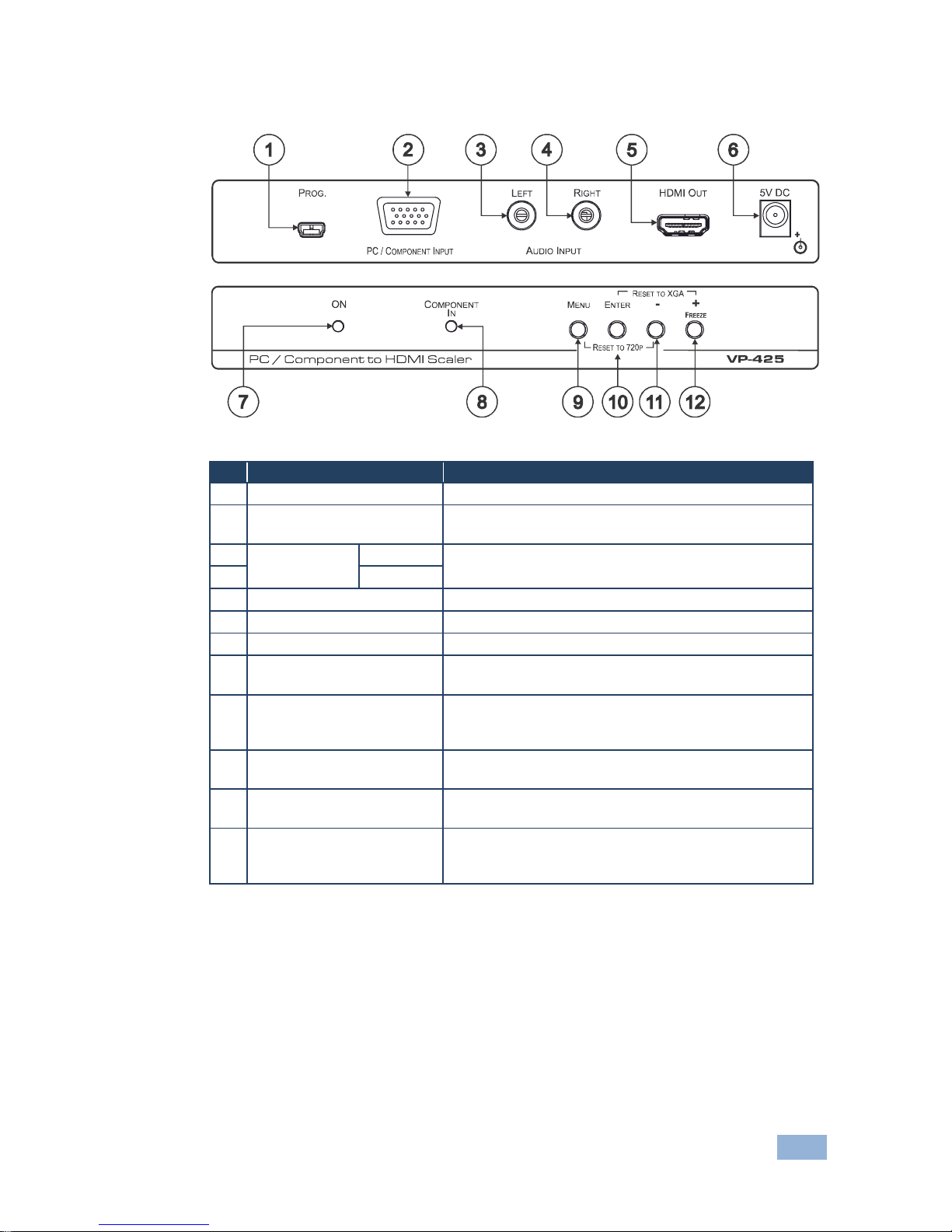
3.1 Defining the VP-425 PC / Component to HDMI Scaler
Figure 1: VP-425 PC / Component to HDMI Scaler
#
Feature
Function
1
PROGRAM USB Connector
For firmware upgrade
2
PC / COMPONENT INPUT
15-pin HD Connector
Connects to a PC or component source
3
AUDIO INPUT
LEFT
Connects to an unbalanced stereo audio source
4
RIGHT
5
HDMI OUT Connector
Connects to an HDMI acceptor
6
5V DC
+5V DC connector for powering the unit
7
ON LED
Lights green when the unit is powered on
8
COMPONENT IN LED
Lights blue when a component (YPbPr) signal is
detected on the input
9
MENU Button
Press to enter/escape the on-screen display (OSD)
menu.
Press together with the – button to reset to 720p
10
ENTER Button
In the OSD, press to choose the highlighted menu item.
Press together with the + button to reset to XGA
11
- Button
In the OSD, press to move backward through the list or
to decrement the parameter value
12
+ / FREEZE Button
In the OSD, press to move forward through the list or to
increment the parameter value.
When not in the OSD, press to freeze the display
Page 9
6
VP-425 - Connecting the VP-425 PC / Component to HDMI Scaler
4 Connecting the VP-425 PC / Component to
HDMI Scaler
Always switch off the power to each device before connecting it to your
VP-425. After connecting your VP-425, connect its power and then
switch on the power to each device.
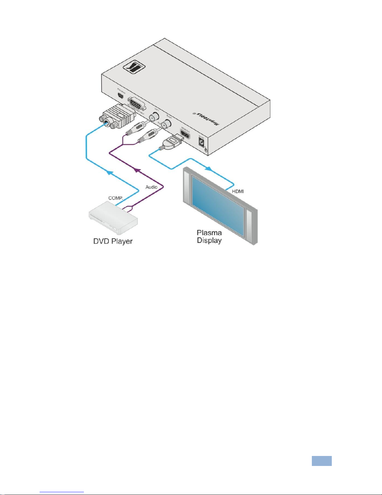
To connect the VP-425, as illustrated in the example in Figure 2 do the following:
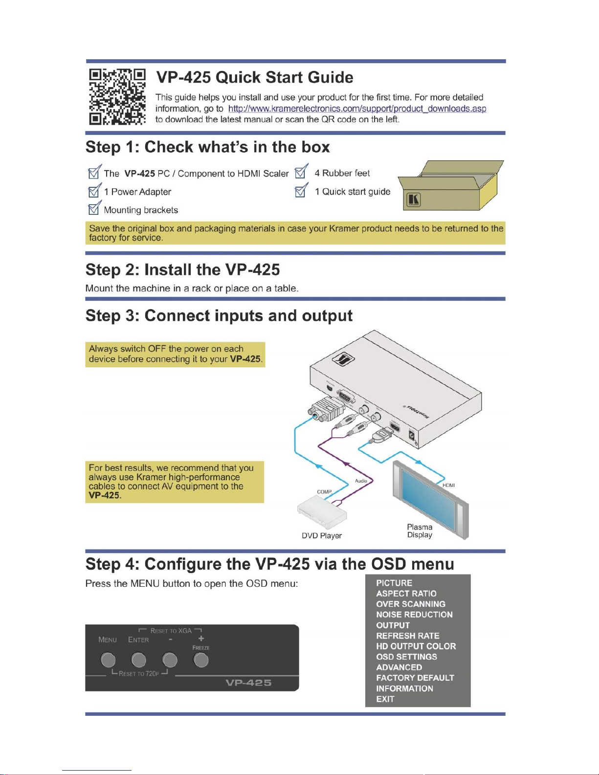
1. Connect a component video source (for example, a DVD player) to the
PC/COMPONENT INPUT 15-pin HD connector as shown in the pinout table
below:
Signal
PIN #
Pr 1 Y 2 Pb
3
Ground
6, 7, 8
Alternatively, you can connect a PC to the 15-pin HD connector
2. Connect an analog stereo audio source (for example, the DVD player audio
signal) to the L and R AUDIO INPUT RCA connectors.
3. Connect the HDMI OUT 15-pin HD connector to an HDMI acceptor (for
example, an LCD display).
4. Connect the 5V DC power adapter to the power socket and connect the
adapter to the mains electricity (not shown in Figure 2).
!
Page 10
VP-425 – Connecting the VP-425 PC / Component to HDMI Scaler
7
Figure 2: Connecting the VP-425 PC / Component to HDMI Scaler
Page 11

8
VP-425 - Controlling the VP-425
5 Controlling the VP-425
The VP-425 can be controlled via:
The front panel buttons (see Section 5.1)
The OSD menu (see Section 5.2)
5.1 Controlling via the Front Panel Buttons
The VP-425 includes the following front panel buttons:
MENU, ENTER, -, and +
FREEZE
RESET TO XGA/720p
5.2 Using the OSD Menu
Press the menu button to enter or close the OSD menu. While the OSD menu is
open, you can use the front panel buttons to perform the following functions. Press
the:
+ and – buttons to move up and down through the menu items and
increment or decrement the parameter values
ENTER button to select and activate a menu item or accept the parameter
value set
MENU button to close the OSD menu
Page 12

VP-425 – Controlling the VP-425
9
As an example of setting parameters, to increase the contrast on the display:
1. From normal operation, press MENU.
The OSD main menu appears on the screen.
2. Press the + or – button to highlight CONTRAST.
CONTRAST changes to green when highlighted.
3. Press ENTER.
The contrast value parameter changes to red.
4. Press the + button to increase the value (increase the contrast) or
the – button to decrease the value (decrease the contrast).
The value ranges from 0 to 100.
5. Press ENTER to set the value.
The contrast value parameter changes back to white.
6. To return to normal operation, highlight EXIT and press ENTER; press
MENU; or wait until the menu times out.
Page 13
10
VP-425 - Controlling the VP-425
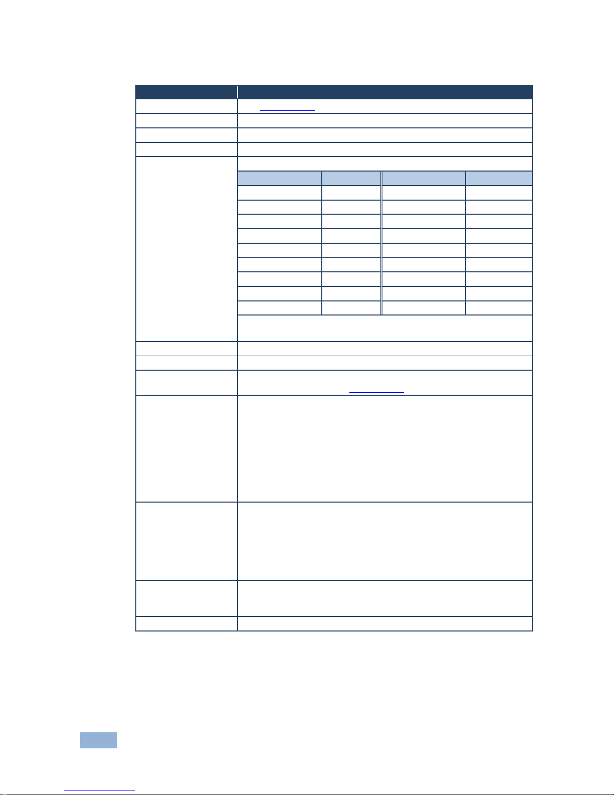
5.2.1 The MAIN MENU
Mode
Function
PICTURE
See Section 5.2.2
ASPECT RATIO
Full, 16:9, 4:3, BEST FIT
OVER SCANNING
Off, 5%, 10%, 15%, 20%
NOISE REDUCTION
Off, Min, Typ, Max
OUTPUT
Select the output resolution from the menu (default 720p):
Output resolution:
Appears as:
Output resolution:
Appears as:
480p
480P
SXGA
1280x1024
576p
576P
WXGA
1360x768
720p
720P
1400x1050
1400x1050
1080i
1080I
WSXGA
1440x900
1080p
1080P
UXGA
1600x1200
VGA
640x480
1680x1050
1680x1050
SVGA
800x600
WUXGA
1920x1200
XGA
1024x768
Native
1280x800
1280x800
NATIVE - Select NATIVE to select the output resolution from the EDID of
the connected HDMI monitor
REFRESH RATE
Select the output refresh rate: FOLLOW, 50Hz, 60Hz
HD OUTPUT COLOR
Select the HD output colorspace: RGB, YPbPr
OSD SETTINGS
Set the OSD parameters: H Position, V Position, Transparency,
Timeout and Display (see Section 5.2.3)
ADVANCED
AUTO SYNC-OFF - Turn the auto sync ON/OFF. When ON, this
deactivates the output after a few minutes if no input is present, until
a valid input is again detected or any button is pressed.
This is useful, for example, when the output is connected to a projector,
and the projector will automatically shut down when it has no input
H OFFSET – adjust the picture H position
V OFFSET – adjust the picture V position
FREEZE – set the function of the FREEZE button: FREEZE + MUTE,
MUTE ONLY, FREEZE ONLY
FACTORY DEFAULT
Resets to the default parameters
If you cannot see the display after factory reset, use the front panel buttons
to set the correct resolution:
To reset to XGA, press the FREEZE (+) and ENTER buttons
simultaneously for about 2 seconds
To reset to 720p press the – and MENU buttons simultaneously for about 2
seconds
INFORMATION
Displays the input and output resolution (via the INFO display) the
SINK connector type and model, the native resolutions and the
software version
EXIT
Select to exit the menu
Page 14
VP-425 – Controlling the VP-425
11
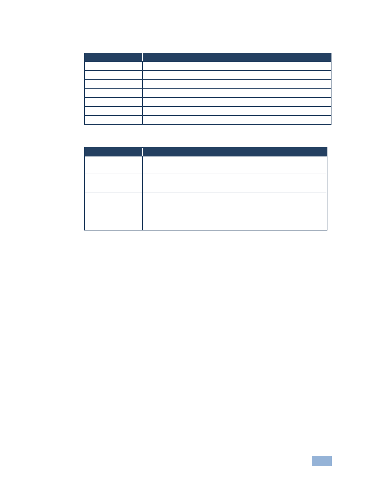
5.2.2 The PICTURE Menu
Parameter
Function
CONTRAST
Set the contrast
BRIGHTNESS
Set the brightness
SATURATION
Set the color saturation
HUE
Set the color hue
SHARPNESS
Set the image sharpness
PHASE
Adjust the clock phase
PICTURE RESET
Reset the PICTURE parameters to their default state
5.2.3 The OSD Menu
Parameter
Function
POSITION
LEFT+TOP, RIGHT-TOP, RIGHT-BTM, LEFT-BTM, CENTER
TRANSPARENCY
Set the OSD background between 0 (solid black) and 15 (transparent)
MENU TIMEOUT
Set the OSD timeout period in seconds (from 5 to 50, OFF)
INFO. TIMEOUT
Set the INFO timeout period in seconds (from 5 to 50, OFF)
INFO. DISPLAY
Select the information shown on the screen during operation:
ON - the information is shown permanently
OFF - the information is not shown
INFO - the information is shown for the time period set in INFO.
TIMEOUT following any change in the resolution
Page 15
12
VP-425 - Technical Specifications
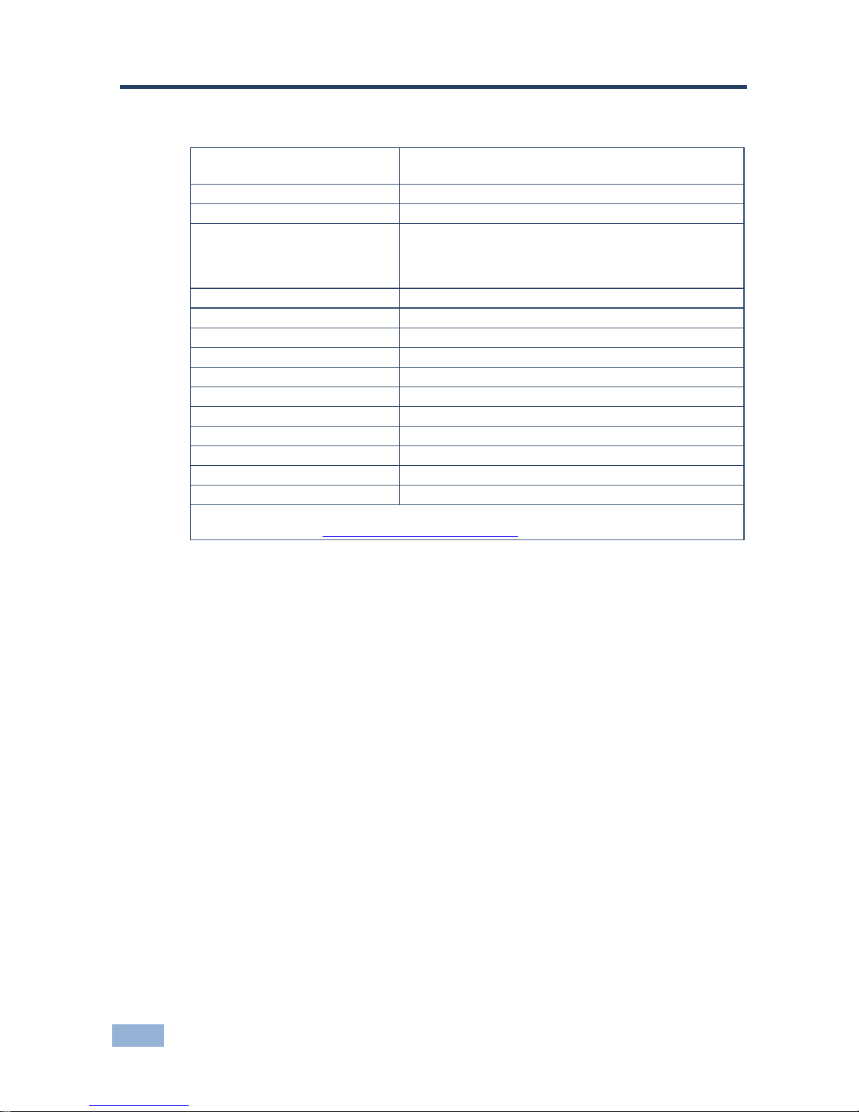
6 Technical Specifications
INPUTS:
1 computer graphics on a 15-pin HD connector
1 unbalanced stereo audio on RCA connectors
OUTPUT:
1 HDMI connector
PORT:
1 USB port
OUTPUT RESOLUTIONS:
480p, 576p, 720p, 1080i, 1080p, 640x480, 800x600,
1024x768, 1280x800, 1280x1024, 1360x768, 1400x1050,
1440x900, 1600x1200, 1680x1050, 1920x1200 and
native
OUTPUT REFRESH RATE:
50/60Hz/follow input
PROCESSING DELAY:
30 ms
CONTROLS:
ON and PC/COMPONENT INPUT LEDs
POWER CONSUMPTION:
5V DC, 400mA
OPERATING TEMPERATURE:
0° to +55°C (32° to 131°F)
STORAGE TEMPERATURE:
-45° to +72°C (-49° to 162°F)
HUMIDITY:
10% to 90%, RHL non-condensing
DIMENSIONS:
18.8cm x 11.4cm x 2.45cm (7.4” x 4.5” x 0.98”) W, D, H
WEIGHT:
0.66kg (1.45lbs) approx.
ACCESSORIES:
Power supply
OPTIONS
RK-T2B 19" rack adapter
Specifications are subject to change without notice
Go to our Web site at http://www.kramerelectronics.com to access the list of resolutions
Page 16
13
Page 17
For the latest information on our products and a list of Kramer distributors,
visit our Web site where updates to this user manual may be found.
We welcome your questions, comments, and feedback.
Web site: www.kramerelectronics.com
E-mail: [email protected]
P/N:
2900-300111
Rev:
3
!
SAFE TY WARNI NG
Disconnect the unit from the power
supply before opening and servicing
 Loading...