


Kramer Electronics, Ltd.
USER MANUAL
Model:
VP-31KSi
3x1 UXGA/Audio STEP-IN Switcher

Contents
i
Contents
1 Introduction 1
2 Getting Started 1
2.1 Quick Start 1
3 Overview 3
3.1 Recommendations for Best Performance 3
3.2 Defining EDID 4
4 Defining the VP-31KSi 3x1 UXGA/Audio STEP-IN Switcher 5
4.1 Using the IR Transmitter for the VP-31KSi 8
5 Connecting the VP-31KSi 3x1 UXGA/Audio STEP-IN Switcher 8
5.1 Connecting the Balanced/Unbalanced Stereo Audio Output 9
5.2 Connecting Remote Contact Closure Input Selection Switches 10
5.3 Connecting the SI-1VGA Remote Step-in Module 11
5.4 Connecting the CAT 5 Twisted Pair Output 12
5.5 Connecting to the VP-31KSi via the RS-232 Port 12
5.6 Connecting to the VP-31KSi via the RS-485 Port 12
5.6.1 Setting the RS-485 Machine Number and Bus Termination DIP-switches 12
5.6.2 Connecting and Controlling Multiple VP-31KSi Devices 13
5.7 Cascading Multiple VP-31KSi Devices 14
5.8 Controlling a Remote RS-232 Device 15
5.9 Connecting to the VP-31KSi via the Ethernet Port 16
5.9.1 Connecting Directly to the Ethernet Port 16
5.9.2 Connecting via a Network Hub, Switch, or Router 18
5.9.3 Configuring the Ethernet Port on the VP-31KSi 18
6 Operating the VP-31KSi Locally via the Front Panel Buttons 18
6.1 Using the Front Panel INPUT SELECTOR Buttons 18
6.2 The Audio-Follow-Video and Breakaway Modes 18
6.2.1 Switching to Breakaway Mode 19
6.2.2 Switching to Audio-Follow-Video Mode 19
6.3 Setting the Audio Output Gain 19
6.4 Reading and Writing the EDID 19
7 Operating the VP-31KSi Remotely 19
8 Operating the VP-31KSi Remotely using a Web Browser 20
8.1 To Log On to the VP-31KSi Web Pages 20
8.2 The Switching Matrix Page 22
8.2.1 Switching an Input to an Output 23
8.2.2 Operating in the Confirm Mode 23
8.3 The Audio Gain Page 24
8.4 The Configurations Page 25
9 Updating the Firmware 25

KRAMER: SIMPLE CREATIVE TECHNOLOGY
Contents
ii
10 Technical Specifications 26
11 Default Parameters 27
11.1 Default Communication Parameters 27
11.2 Default Audio and Video Parameters 27
11.3 Default EDID 28
12 Table of ASCII Codes for Serial Communication (Protocol 3000) 29
13 Table of Hex Codes for Serial Communication (Protocol 2000) 29
14 Kramer Protocol 31
14.1 Switching Protocols 31
14.1.1 Switching Protocols via the Front Panel Buttons 31
14.1.2 Switching Protocols via Protocol Commands 31
14.2 Kramer Protocol 3000 31
14.2.1 Protocol 3000 Syntax 32
14.2.2 Command Part Details 32
14.3 Kramer Protocol 2000 38
Figures
Figure 1: VP-31KSi 3x1 UXGA/Audio STEP-IN Switcher Front Panel 5
Figure 2: VP-31KSi 3x1 UXGA/Audio STEP-IN Switcher Rear Panel 6
Figure 3: Connecting the VP-31KSi 8
Figure 4: Balanced Stereo Audio Connection 10
Figure 5: Unbalanced Stereo Audio Connection 10
Figure 6: Remote Input Selection Switch Wiring 10
Figure 7: Connecting the SI-1VGA 11
Figure 8: Connecting to the RS-232 Communication Port 12
Figure 9: RS-485 DIP-switch Default Setting 13
Figure 10: Cascading up to Eight VP-31KSi Devices 15
Figure 11: Local Area Connection Properties Window 17
Figure 12: Internet Protocol (TCP/IP) Properties Window 17
Figure 13: Java Test Page Success Message 20
Figure 14: The Loading Page 21
Figure 15: First Time Security Warning 21
Figure 16: VP-31KSi Switching Matrix Page 22
Figure 17: Switching an Input to an Output 23
Figure 18: Switching an Input to an Output 23
Figure 19: Exiting Offline Warning 24
Figure 20: Audio Gain Page 24
Figure 21: Configurations Page 25

Contents
iii
Tables
Table 1: VP-31KSi 3x1 UXGA/Audio STEP-IN Switcher Front Panel Features 5
Table 2: VP-31KSi 3x1 UXGA/Audio STEP-IN Switcher Rear Panel Features 7
Table 3: RS-485 DIP-switch Settings 13
Table 4: Machine Number DIP-switch Settings 13
Table 5: Button Illumination Descriptions 18
Table 6: Technical Specifications of the VP-31KSi 26
Table 7: Default Communication Parameters 27
Table 8: Default Audio and Video Parameters 27
Table 9: VP-31KSi Video and Audio Signal Codes 29
Table 10: VP-31KSi Audio Input Gain Codes 29
Table 11: VP-31KSi Audio and Audio Output Gain Codes 29
Table 12: VP-31KSi Hex Codes for Protocol 2000 30
Table 13: VP-31KSi Hex Codes that Increase/Decrease Audio Input Gain 30
Table 14: Hex Codes that Set the Audio Input Gain 30
Table 15: VP-31KSi Hex Codes for Increasing/Decreasing the Output Gain 30
Table 16: Hex Codes for Setting the Audio Output Gain 30
Table 17: Instruction Codes for Protocol 3000 33
Table 18: Protocol Definitions 39
Table 19: Instruction Codes for Protocol 2000 40

Introduction
1
1 Introduction
Welcome to Kramer Electronics! Since 1981, Kramer Electronics has been
providing a world of unique, creative, and affordable solutions to the vast range of
problems that confront the video, audio, presentation, and broadcasting
professional on a daily basis. In recent years, we have redesigned and upgraded
most of our line, making the best even better! Our 1,000-plus different models now
appear in 11 groups
1
Congratulations on purchasing your Kramer VP-31KSi 3x1 UXGA/Audio STEP-IN
Switcher.
that are clearly defined by function.
The VP-31KSi is ideal for:
• Display systems requiring simple input selection
• Remote monitoring of computer activity in schools and businesses
• Rental/staging applications
• Multimedia and presentation source selection
The package includes the following items:
• VP-31KSi 3x1 UXGA/Audio STEP-IN Switcher
• Infrared RC-IR3 remote control transmitter (including the required battery
and a separate user manual
2
)
• This user manual
2
• Power adapter
2 Getting Started
We recommend that you:
• Unpack the equipment carefully and save the original box and packaging
materials for possible future shipment
• Review the contents of this user manual
• Use Kramer high-performance high-resolution cables
3
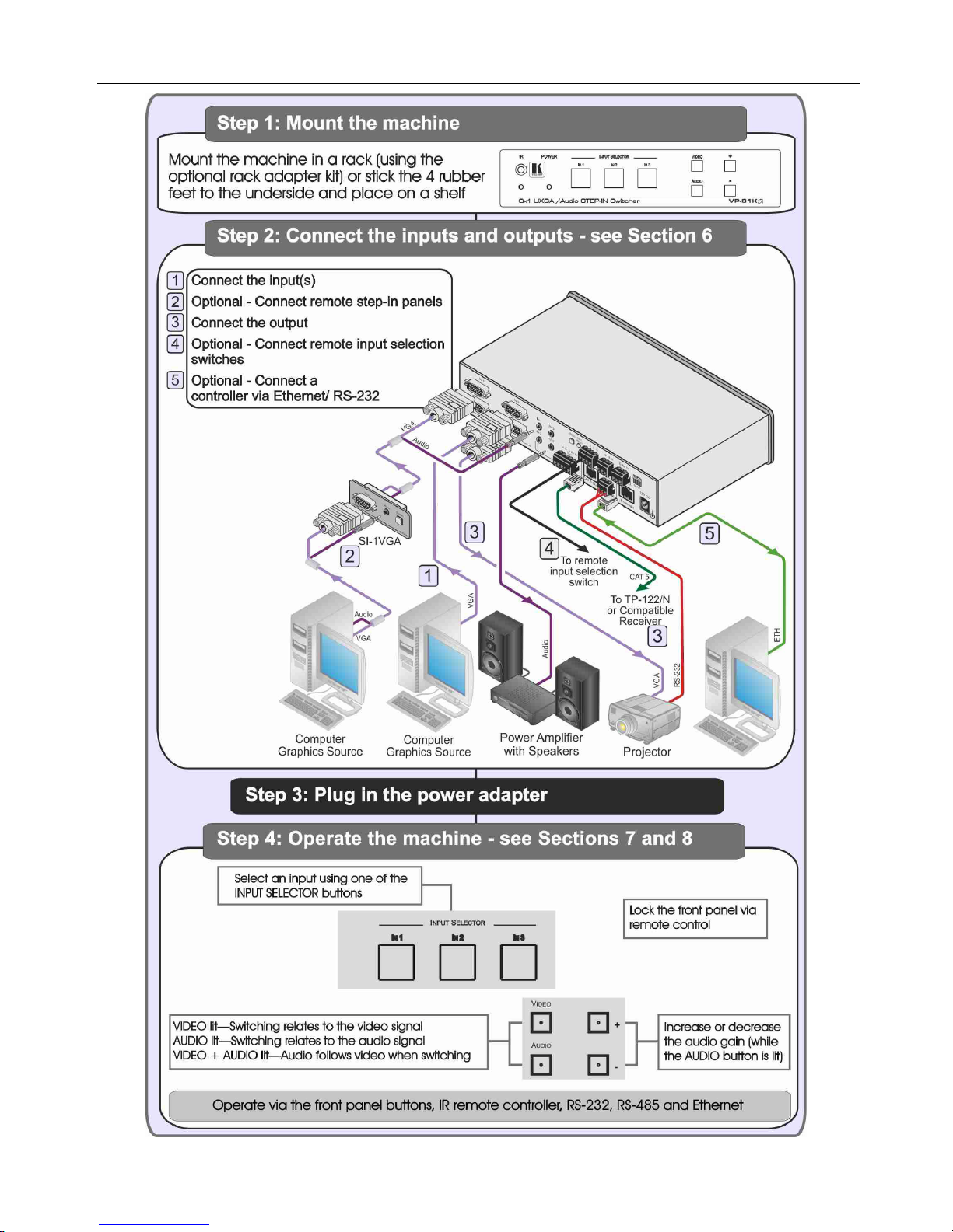
2.1 Quick Start
This quick start chart summarizes the basic setup and operation steps.
1 GROUP 1: Distribution Amplifiers; GROUP 2: Switchers and Matrix Switchers; GROUP 3: Control Systems; GROUP 4:
Format/Standards Converters; GROUP 5: Range Extenders and Repeaters; GROUP 6: Specialty AV Products; GROUP 7: Scan
Converters and Scalers; GROUP 8: Cables and Connectors; GROUP 9: Room Connectivity; GROUP 10: Accessories and Rack
Adapters; GROUP 11: Sierra Products
2 Download up-to-date Kramer user manuals from http://www.kramerelectronics.com
3 The complete list of Kramer cables is available from http://www.kramerelectronics.com
KRAMER: SIMPLE CREATIVE TECHNOLOGY
Getting Started
2

Overview
3
3 Overview
The VP-31KSi routes one of three video and audio inputs to the video and audio
(balanced or unbalanced) outputs. It also converts the video and audio signals into
a TP (Twisted Pair) signal for transmission over TP cable to any compatible TP
receiver (for example, the Kramer TP-120).
In particular, the VP-31KSi:
• Features a very high video bandwidth ensuring transparent UXGA
performance
• Features audio-follow-video (AFV) in which all operations relate to both the
video and the audio channels, or the audio breakaway option, in which video
and audio channels are switched independently
• Includes a volume control
• Includes the Kramer innovative integrated sync processing Kr-isp™
technology, which lets you achieve a sharp, stable image even when the
sync level is too low, by restoring the sync signal waveform
• I-EDIDPro™ Kramer Intelligent EDID Processing™ – Intelligent EDID
handling & processing algorithm ensures Plug and Play operation for analog
systems
• Supports the cascading of up to eight devices to provide a single virtual
switcher with up to 17 inputs
• Supports the Kramer Remote Step-In Panels (for example, the SI-1VGA,
WSI-1VGA or SI-VGAT) for remote inputs and remote step-in control
You can control the VP-31KSi using the front panel buttons, or remotely via:
• RS-485 or RS-232 serial commands transmitted by a touch screen system,
PC or other serial controller
• Ethernet over a LAN using a Web browser
• Kramer Remote Step-in Panels (for example, the SI-1VGA or SI-VGAT)
• The Kramer RC-IR3 Infrared Remote Control Transmitter
• Remote, contact closure switches
3.1 Recommendations for Best Performance
To achieve the best performance:
• Use only high quality connection cables
1
• Avoid interference from neighboring electrical appliances that may
adversely influence signal quality and position your Kramer
VP-31KSi away from moisture, excessive sunlight and dust
to avoid interference, deterioration
in signal quality due to poor matching, and elevated noise levels (often
associated with low quality cables).
1 Available from Kramer Electronics and listed on our Web site at http://www.kramerelectronics.com

KRAMER: SIMPLE CREATIVE TECHNOLOGY
Overview
4
!
Caution: No operator serviceable parts inside the unit
Warning:
Use only the Kramer Electronics input power wall
adapter that is provided with the unit
Warning:
Disconnect the power and unplug the unit from the wall
before installing
3.2 Defining EDID
The Extended Display Identification Data (EDID
1
) is a data-structure, provided by
a display that describes its capabilities to a graphics card (that is connected to the
display’s source). The EDID enables the PC or laptop to “know” what kind of
monitor is connected to the output. The EDID includes the manufacturer’s name,
product type, timing data supported by the display, display size, luminance data
and (for digital displays only) pixel mapping data.
1 Defined by a standard published by the Video Electronics Standards Association (VESA)
Defining the VP-31KSi 3x1 UXGA/Audio STEP-IN Switcher
5
4 Defining the VP-31KSi 3x1 UXGA/Audio STEP-IN Switcher
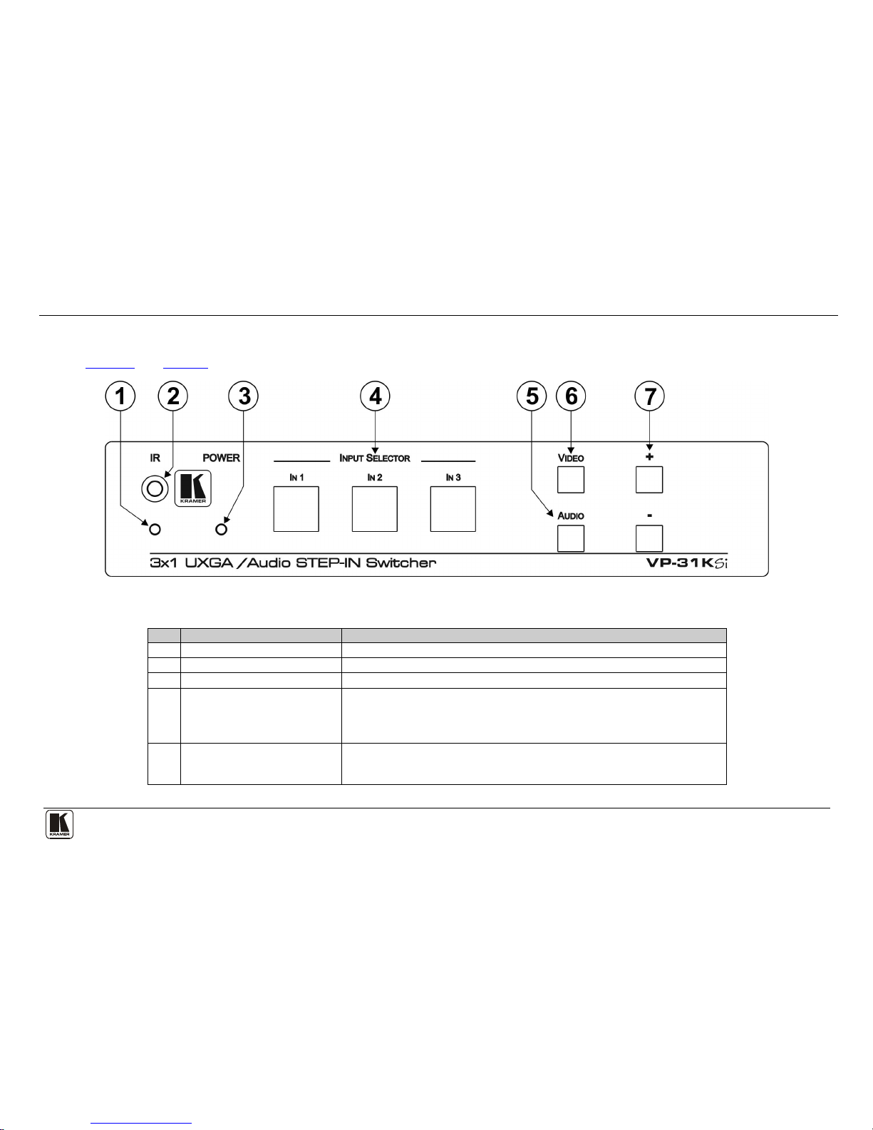
Figure 1 and Table 1 define the front panel of the VP-31KSi 3x1 UXGA/Audio STEP-IN Switcher.
Figure 1: VP-31KSi 3x1 UXGA/Audio STEP-IN Switcher Front Panel
Table 1: VP-31KSi 3x1 UXGA/Audio STEP-IN Switcher Front Panel Features
#
Feature
Function
1 IR LED Lights yellow when the unit receives an IR signal
2 IR Sensor Receiver for the IR Remote Control signal
3 POWER LED Lights green when the unit receives power
4 INPUT SELECTOR IN 1 ~ IN 3
Buttons
Press to select the input (from 1 to 3) to switch to the outputs.
The button lights red if it is selected and there is no input signal.
The button lights green if it is not selected but there is an input signal at that input.
The button lights violet if it is selected and there is an input signal connected
5 AUDIO Button Press to execute audio related actions.
The button lights when the audio mode is operational.
When both the Audio and Video buttons light, the device is in audio follow video mode
KRAMER: SIMPLE CREATIVE TECHNOLOGY
Defining the VP-31KSi 3x1 UXGA/Audio STEP-IN Switcher
6
#
Feature
Function
6 VIDEO Button Press to execute video related actions.
The button lights when the video mode is operational.
When both the Audio and Video buttons light, the device is in audio follow video mode
7
AUDIO GAIN Buttons
+ Press to increase the audio output level of the selected input
1
–
Press to decrease the audio output level of the selected input1
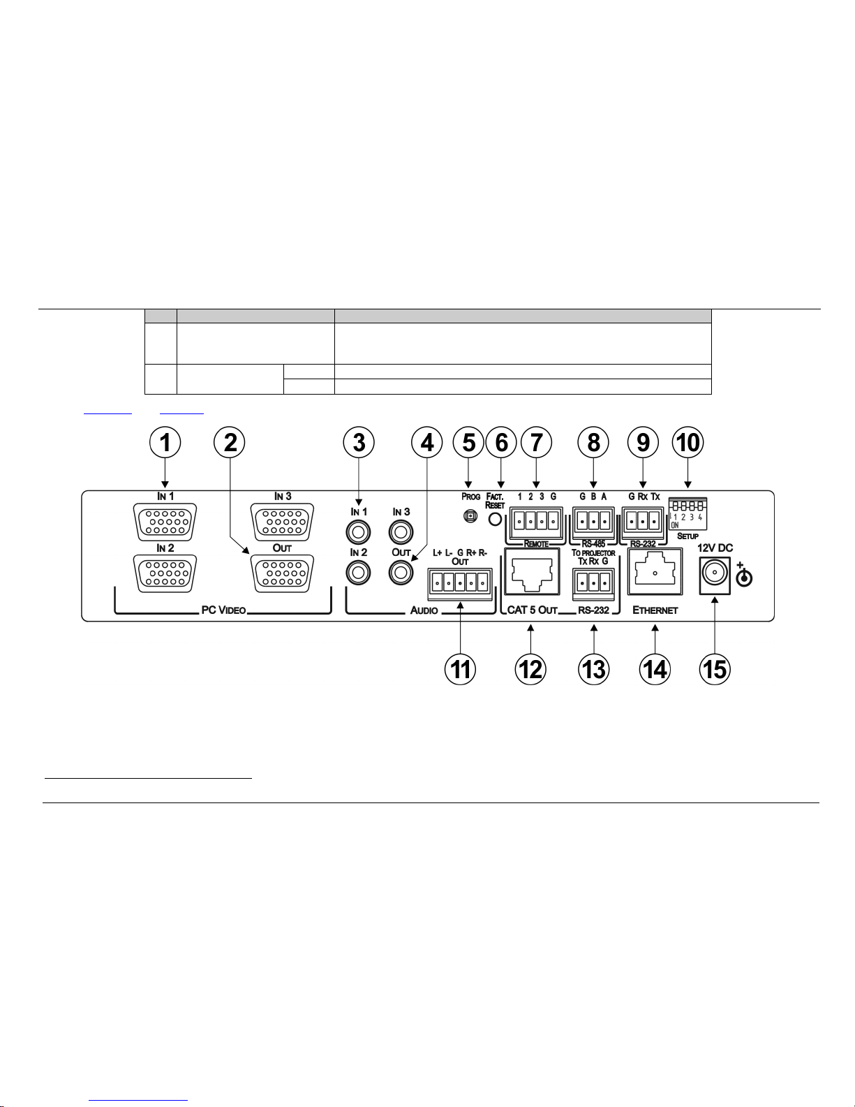
Figure 2 and Table 2 define the rear panel of the VP-31KSi 3x1 UXGA/Audio STEP-IN Switcher.
Figure 2: VP-31KSi 3x1 UXGA/Audio STEP-IN Switcher Rear Panel
1 While the AUDIO button is lit
Defining the VP-31KSi 3x1 UXGA/Audio STEP-IN Switcher
7
Table 2: VP-31KSi 3x1 UXGA/Audio STEP-IN Switcher Rear Panel Features
#
Feature
Function
1 PC VIDEO IN 1 ~ IN 3 15-pin HD (F) Connectors Connect to the VGA (up to W UXGA) sources (from 1 to 3)
2 OUT 15-pin HD Connector Connect to the VGA (up to W UXGA) acceptor
3 AUDIO IN 1 ~ IN 3 3.5mm Mini Jacks Connect to the unbalanced stereo audio sources (from 1 to 3)
4 AUDIO OUT 3.5mm Mini Jack Connect to the unbalanced stereo audio acceptor
5 PROG Button For the use of Kramer technical support only
6 FACT. RESET Button Press and hold while turning the unit on to reset all parameters to their factory default values (see
Section
11)
7 REMOTE Switch 4-pin Terminal Block Connect to contact closure switches (1 to 3) for duplicating the function of the front panel Input
Selector buttons (see Section
5.2)
8 RS-485 3-pin Terminal Block Connect to RS-485 port on a remote controller or another VP-31KSi (see Section 5.6)
9 RS-232 3-pin Terminal Block Connect to the RS-232 port on a remote controller (see Section 5.5)
10 SETUP 4-way DIP-switch DIP-switches: 1, 2 and 3 assign the RS-485 machine number (see Section 5.6.1)
Switch 4 sets the RS-485 termination on or off (see Section
5.6.1)
11 AUDIO OUT 5-pin Terminal Block Connector Connect to the balanced stereo audio acceptor
12 CAT 5 OUT RJ-45 Connector Connect to a compatible TP receiver (for example, TP-122/N)
13 TO PROJECTOR RS-232-2 3-pin Terminal Block Connect to an RS-232 controllable device, for example, a projector (see Figure 3 and Section 5.8)
14 ETHERNET RJ-45 Connector Connect to a remote controller via a LAN (see Section 5.9)
15 12V DC Power Connector Connect the mains power adapter (center pin positive)
KRAMER: SIMPLE CREATIVE TECHNOLOGY
Connecting the VP-31KSi 3x1 UXGA/Audio STEP-IN Switcher
8
4.1 Using the IR Transmitter for the VP-31KSi
You can use the RC-IR3 IR transmitter to operate the machine via the built-in IR
receiver on the front panel.
5 Connecting the VP-31KSi 3x1 UXGA/Audio STEP-IN Switcher
i
Always switch off the power to each device before connecting it to your
VP-31KSi. After connecting your VP-31KSi, connect its power and then
switch on the power to each device.
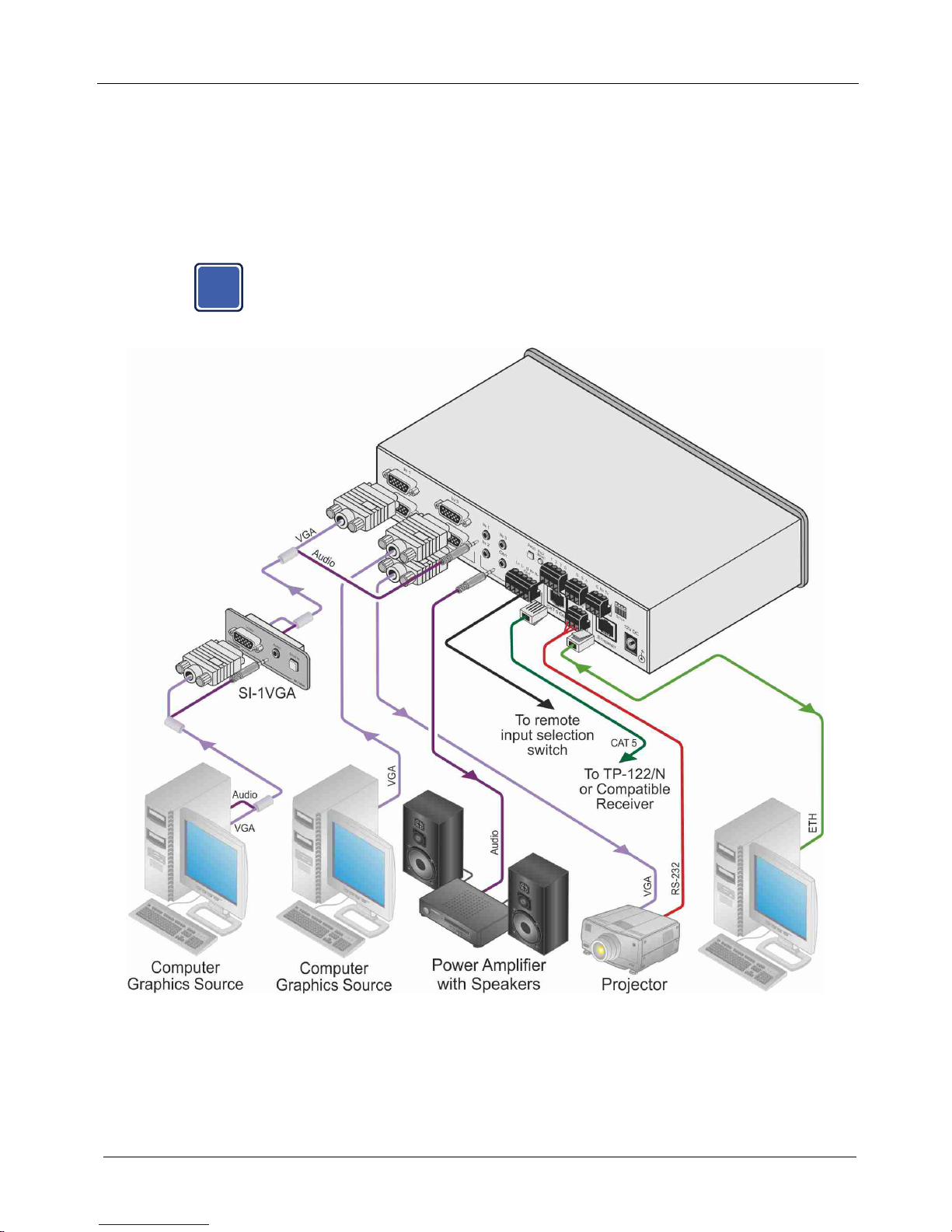
Figure 3: Connecting the VP-31KSi

Connecting the VP-31KSi 3x1 UXGA/Audio STEP-IN Switcher
9
To connect
1
Figure 3 the VP-31KSi, as illustrated in the example in :
1. Connect up to three
2
Remote Step-in Panels (for example, the SI-1VGA or
SI-VGAT) to the VP-31KSi 15-pin HD VIDEO INPUT connectors
3
2. Connect up to three UXGA computer graphics sources to the SI-1VGA
15-pin HD video connectors.
and to
the 3.5mm mini jacks (from 1 to 3).
3. Connect up to three unbalanced audio sources to the 3.5mm mini jack audio
connectors on the SI-1VGA panels.
4. Connect the 15-pin HD VIDEO OUTPUT connector to a UXGA acceptor (for
example, a projector).
5. Connect the RJ-45 CAT 5 OUT connector to a compatible TP receiver (for
example, the Kramer TP-120).
6. Connect either, but not both:
the unbalanced audio 3.5mm AUDIO OUTPUT jack to an unbalanced
audio acceptor (for example, power amplifier)
—OR—
the balanced audio 5-pin terminal block (see Section
5.1) to an audio
acceptor (not shown in
Figure 3)
7. Connect up to three remote, contact closure input selection switches to the
REMOTE terminal block (see Section
5.2).
8. Connect a PC over a LAN to the Ethernet for remote operation.
9. Set the DIP-switches (see Section
5.6.1) for remote operation. You can
connect a PC and/or controller to the:
RS-232 port (see Section
5.3)
RS-485 port (see Section
5.6.1)
10. Connect the power adapter to the device and to the mains electricity.
5.1 Connecting the Balanced/Unbalanced Stereo Audio Output
This section illustrates how to wire the devices to the balanced audio output:
• A balanced stereo output connection, see
Figure 4
• An unbalanced stereo output connection, see
Figure 5
1 Be sure that the power is switched off on each device before connecting it to your VP-31KSi. After connecting all the devices to your
VP-31KSi, switch on the power of the VP-31KSi, and then switch on the power of each device
2 You do not have to connect all the inputs
3 The cable used must connect all 15 pins
KRAMER: SIMPLE CREATIVE TECHNOLOGY
Connecting the VP-31KSi 3x1 UXGA/Audio STEP-IN Switcher
10
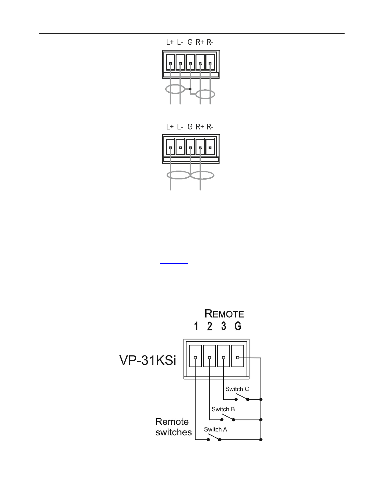
Figure 4: Balanced Stereo Audio Connection
Figure 5: Unbalanced Stereo Audio Connection
5.2 Connecting Remote Contact Closure Input Selection Switches
You can connect remote input selection switches to the Remote terminal block on
the rear panel of the VP-31KSi which enables you to remotely activate the relevant
input.
The following example (see
Figure 6) illustrates three switches (A, B and C)
connected to remotely control inputs 1, 2 and 3 respectively (up to three switches
can be connected). Pressing switch A causes input 1 on the VP-31KSi to be the
active input, pressing switch B causes input 2 to be the active input, and pressing
switch C causes input 3 to be the active input.
Figure 6: Remote Input Selection Switch Wiring
Connecting the VP-31KSi 3x1 UXGA/Audio STEP-IN Switcher
11
To connect remote input selection switches as the example illustrated in
Figure 6:
1. Connect Switch A to pins 1 and G (ground) on the terminal block.
2. Connect Switch B to pins 2 and G on the terminal block.
3. Connect Switch C to pins 3 and G on the terminal block.
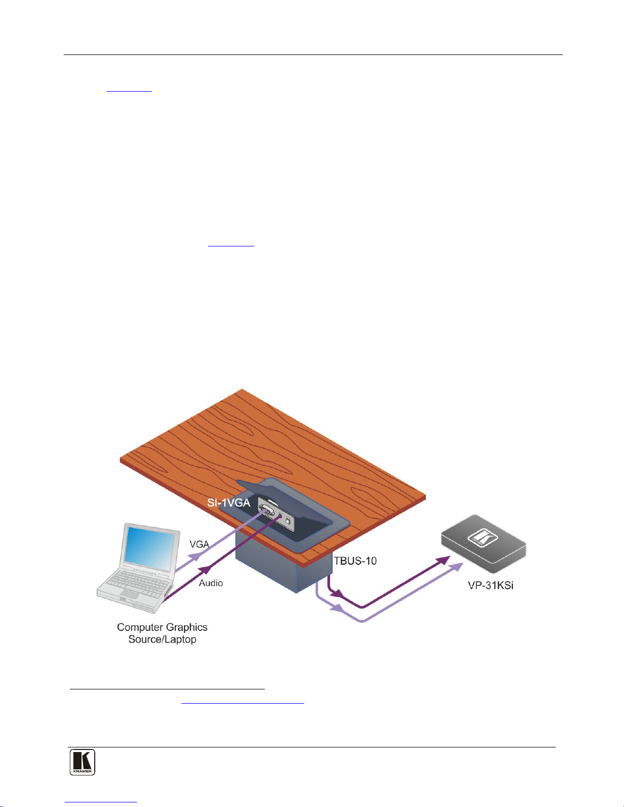
5.3 Connecting the SI-1VGA Remote Step-in Module
For detailed instructions refer to the SI-1VGA Step-in Module Installation
Instructions
1
To connect an SI-1VGA remote step-in module to the VP-31KSi as illustrated
in the example in
.
Figure 7:
1. Mount the SI-1VGA in either the TBUS-10 or the K-POD301.
2. Using a 15-pin HD (male to male) cable
2
3. Using an audio cable with 3.5mm mini jacks at both ends
, connect the 15-pin HD connector
on the rear of the SI-1VGA to the corresponding input on the rear of the
VP-31KSi.
3
4. Repeat steps 2 and 3 for each SI-1VGA remote step-in module.
, connect the
3.5mm mini connector on the rear of the SI-1VGA to the corresponding audio
input on the rear of the VP-31KSi.
Figure 7: Connecting the SI-1VGA
1 Available for download from http://www.kramerelectronics.com
2 For example, Kramer C-GM/GM
3 For example, Kramer C-A35M/A35M
 Loading...