

Page 1

Kramer Electronics, Ltd.
Preliminary
USER MANUAL
Model:
VP-26
Presentation Matrix Switcher
Page 2

Contents
i
Contents
1 Introduction 1
2 Getting Started 1
2.1 Quick Start 2
3 Overview 3
3.1 About the VP-26 3
3.2 About the Power Connect™ Feature 4
3.3 Shielded Twisted Pair (STP) / Unshielded Twisted Pair (UTP) 4
3.4 Recommendations for Achieving the Best Performance 5
3.5 Terminology Used in this User Manual 5
4 Your Presentation Matrix Switcher 5
5 Installing the VP-26 on a Rack 11
6 Connecting the VP-26 Presentation Matrix Switcher 12
6.1 Connecting the VP-26 Rear Panel 12
6.2 Connecting the Balanced/Unbalanced Stereo Audio Input/Output 15
6.3 Wiring the CAT 5 LINE OUT RJ-45 Connector 15
6.4 Connecting a PC 16
6.5 Connecting via RS-485 16
6.6 Controlling via ETHERNET 17
6.6.1 Connecting the ETHERNET Port directly to a PC (Crossover Cable) 17
6.6.2 Connecting the ETHERNET Port via a Network Hub (Straight-Through Cable) 19
6.6.3 Control Configuration via the Ethernet Port 19
6.7 Controlling via RS-232 and RS-485 19
6.8 DIP-switch Settings 21
6.8.1 Setting the Machine # DIP-switches 21
7 Operating Your Switcher 22
7.1 The Front Panel Buttons 22
7.2 The Independent Switchers AFV Mode 23
7.3 The Master Audio Breakaway Mode 25
8 Flash Memory Upgrade 26
8.1 Switcher Flash Memory Upgrade 26
8.1.1 Downloading from the Internet 26
8.1.2 Connecting the PC to the RS-232 Port 26
8.1.3 Upgrading Firmware 27
8.2 Ethernet Flash Memory Upgrade 31
8.2.1 Downloading from the Internet 32
8.2.2 Connecting the PC to the RS-232 Port 32
8.2.3 Upgrading Firmware 32
9 Technical Specifications 34
10 Hex Table 35
Page 3

KRAMER: SIMPLE CREATIVE TECHNOLOGY
Contents
ii
10.1 Audio Gain Control Hex Tables 36
11 Communication Protocol 38
Figures
Figure 1: VP-26 Presentation Matrix Switcher – Front View 6
Figure 2: VP-26 Presentation Matrix Switcher – Rear View 8
Figure 3: VP-26 Presentation Switcher / Controller – Underside View 10
Figure 4: Connecting the VP-26 Presentation Matrix Switcher 14
Figure 5: Connecting a Balanced Stereo Audio Input/Output 15
Figure 6: Connecting an Unbalanced Stereo Audio Input 15
Figure 7: Connecting an Unbalanced Stereo Audio Output 15
Figure 8: CAT 5 PINOUT 15
Figure 9: Connecting a PC Without a null-modem Adapter 16
Figure 10: Controlling via RS-485 (for example, using an RC-3000) 17
Figure 11: Local Area Connection Properties Window 18
Figure 12: Internet Protocol (TCP/IP) Properties Window 18
Figure 13: Control Configuration via RS-232 and RS-485 20
Figure 14: Default DIP-switch Settings 21
Figure 15: Independent Switchers Mode 24
Figure 16: Switching in the Master Audio Mode 25
Figure 17: Switching to the MIC in the Master Audio Mode 25
Figure 18: Splash Screen 27
Figure 19: Atmel – Flip Window 27
Figure 20: Device Selection Window 28
Figure 21: Selecting the Device from the Selection Window 28
Figure 22: Loading the Hex 29
Figure 23: RS-232 Window 29
Figure 24: Atmel – Flip Window (Connected) 30
Figure 25: Atmel – Flip Window (Operation Completed) 31
Figure 26: The KFR-Programmer Window 32
Page 4

Contents
iii
Tables
Table 1: Terminology Used in this User Manual 5
Table 2: Front Panel VP-26 Presentation Matrix Switcher Features 7
Table 3: Rear Panel VP-26 Presentation Matrix Switcher Features 9
Table 4: VP-26 Underside Panel Features 10
Table 5: CAT 5 PINOUT 15
Table 6: DIP-switch Settings 21
Table 7: Machine # DIP-switch Settings 21
Table 8: Technical Specifications of the VP-26 Presentation Switcher 34
Table 9: VP-26 Hex Table Video and Audio In-group IN-OUT 1 Selector 35
Table 10: VP-26 Hex Table Video and Audio In-group IN-OUT 2 Selector 35
Table 11: VP-26 Master Audio Selector Hex Table 36
Table 12: Set the Audio OUT 1 Gain Control for the Groups 36
Table 13: Set the Audio OUT 2 Gain Control for the Groups 36
Table 14: Set the Audio Output Gain Control for the Microphone 36
Table 15: Set the Audio Output Gain Control for the Master Audio 37
Table 16: Increase or Decrease the Audio Out 1 Gain by One Step 37
Table 17: Protocol Definitions 38
Table 18: Instruction Codes 39
Page 5

Introduction
1
1 Introduction
Welcome to Kramer Electronics! Since 1981, Kramer Electronics has been
providing a world of unique, creative, and affordable solutions to the vast
range of problems that confront the video, audio, presentation, and
broadcasting professional on a daily basis. In recent years, we have
redesigned and upgraded most of our line, making the best even better! Our
1,000-plus different models now appear in 11 groups
1
that are clearly
defined by function.
Thank you for purchasing the Kramer VP-26 Presentation Matrix Switcher,
which is ideal for:
• Presentation and conference room systems
• Production studios
• Rental and staging
The package includes the following items:
• VP-26 Presentation Matrix Switcher
• Windows
®
-based Kramer control software
• Null-modem adapter and power cord
2
• Kramer RC-IR3 Infrared Remote Control Transmitter (including
the required battery and a separate user manual
3
)
• This user manual
3
2 Getting Started
We recommend that you:
• Unpack the equipment carefully and save the original box and
packaging materials for possible future shipment
• Review the contents of this user manual
• Use Kramer high performance high resolution cables
4
1 GROUP 1: Distribution Amplifiers; GROUP 2: Switchers and Matrix Switchers; GROUP 3: Control Systems;
GROUP 4: Format/Standards Converters; GROUP 5: Range Extenders and Repeaters; G ROUP 6: Specialty AV Products;
GROUP 7: Scan Converters and Scalers; GROUP 8: Cables and Connectors; GROUP 9: Room Connectivity;
GROUP 10: Accessories and Rack Adapters; GROUP 11: Sierra Products
2 We recommend that you use only the power cord that is supplied with this machine
3 Download up-to-date Kramer user manuals from our Web site at http://www.kramerelectronics.com
4 The complete list of Kramer cables is on our Web site at http://www.kramerelectronics.com
Page 6

KRAMER: SIMPLE CREATIVE TECHNOLOGY
Getting Started
2
2.1 Quick Start
This quick start chart summarizes the basic setup and operation steps.
Page 7

Overview
3
3 Overview
This section describes:
• A summary of the VP-26, see section 3.1
• The power connect feature, see section 3.2
• Using shielded twisted pair (STP)/unshielded twisted pair (UTP), see
section 3.3
• Recommendations for achieving the best performance, see section 3.4
• The terminology used in this user manual, see section 3.5
3.1 About the VP-26
The VP
-26 is a high quality one-box presentation matrix switcher, which
includes three independent 4x2 audio/video matrix switchers, one
independent 2x2 audio/video matrix switcher and a master audio switcher.
It combines the functions of a 4x2 matrix switcher for computer graphics
(VGA/UXGA) signals with audio, a 4x2 matrix switcher for composite
video and audio, a 4x2 matrix switcher for s-Video and audio, and a 2x2
matrix switcher for component video (Y, P
B/CB, PR/CR) as well as the
master audio switcher that routes one of the pre-selected audio inputs (from
these four switchers) to two separate outputs.
In addition, the VP-26 features:
• A VGA/UXGA video bandwidth of 300MHz to ensure transparent
performance even in the most critical applications, and is HDTV
compatible
• A composite/ SDI video bandwidth of 420MHz, an s-Video bandwidth
of 320MHz, a component video bandwidth of 380MHz, and a CAT 5
resolution of up to UXGA
• 37 selector buttons, microphone input level control and master audio
level control
• Microphone talk-over mode (the microphone input signal lowers the
line audio output level when the connected microphone detects sound)
• A CAT 5 output, with a transmission range of more than 300 feet (over
100 meters) that transmits the OUT 2 VGA/UXGA video and audio
signals to a remote acceptor via a receiver
• An internal 5-Watt per channel (24kHz, 3dB), stereo power amplifier
for connecting the speakers directly to the machine
• A panel LOCK button to prevent tampering with the front panel
• Previous setup recall via the non-volatile memory after power up
• Changing the audio output levels via RS-232 commands
Page 8

KRAMER: SIMPLE CREATIVE TECHNOLOGY
Overview
4
Control the VP-26 using the front panel buttons, or remotely via:
• RS-485 or RS-232 serial commands transmitted by a touch screen
system, PC, or other serial controller
• The Kramer infrared remote control transmitter
• The ETHERNET
3.2 About the Power Connect™ Feature
The Power
Connect feature means that only one unit in a system, the
transmitter or the receiver, needs to be connected to a power source when
the devices are within 150 feet (50 meters) of each other.
The Power Connect feature applies as long as the cable can carry power. The
distance does not exceed 50 meters on standard CAT 5 cable. For longer
distances, heavy-gauge cable shoul d be used
1
.
For a CAT 5 cable exceeding a distance of 50 meters, separate power supplies
should be connected to the transmitter and to the receiver simult aneously.
3.3 Shielded Twisted Pair (STP) / Unshielded Twisted Pair (UTP)
We
recommend that you use shielded twisted pair (STP) cable. There are
different levels of STP cable available, and we advise you to use the best
quality STP cable that you can afford. Our non-skew-free cable, Kramer
BC-STP is intended for digital signals and for analog signals where
skewing is not an issue. For cases where there is skewing, our UTP
skew-free cable, Kramer BC-XTP, may be used. Bear in mind, though, that
we advise using STP cables where possible, since the compliance to
electromagnetic interference was tested using those cables.
Although unshielded twisted pair (UTP) cable might be preferred for long
range applications, the UTP cable should be installed far away from electric
cables, motors and so on, which are prone to create electrical interference .
However, since the use of UTP cable m ight cause inconformity to
electromagnetic standards, Kramer does not commit to meeting the standard
with UTP cable.
1 CAT 5 cable is still suitable for the video/audio transmission, but not for feeding the power at these distances
Page 9

Your Presentation Matrix Switcher
5
3.4 Recommendations for Achieving the Best Performance
To achieve the best performance:
• Use only good quality connection cables
1
to avoid interference,
deterioration in signal quality due to poor matching, and elevated
noise levels (often associated with low quality cables).
• Avoid interference from neighboring electrical appliances that
may adversely influence signal quality and position your Kramer
VP-26 away from moisture, excessive sunlight and dust
3.5 Terminology Used in this User Manual
Table 1
defines some terms that are used in this user manual.
Table 1: Terminology Used in this User Manual
Term Definition
802.3 The standard specification for ETHERNET that is maintained by the Institute of Electrical
and Electronics Engineer s (IEEE).
Dynamic Host
Configuration
Protocol (DHCP)
Allows the network administrator to distribute IP addresses from a central point and
automatically send a new IP address when an Ethernet point is plugged into a different
network loca tion .
Gateway A network position serving as an entry to another network. On the Internet, a node or
stopping point can be either a gatew ay node or a host (end-p oint) node.
IP Address A 32-binary digit number that identifies each sender or receiver (within a network via a
particular server or worksta tion) of data (H TML pages or e-mails) tha t is sent in packets
across the Internet. Every device connected to an IP network must have a unique IP
address. This address is used to reference the specific unit.
Local Area N etw ork
(LAN)
Computers sharing a common communications line or wireless link, which often share a
server within a defined geographic area.
Media Access
Control (MAC)
Address
A computer's unique hardw are numbe r (or addr ess) in a LAN or othe r networ k. On an
Ethernet LAN, the (MAC) address is identical to the Ethernet address.
Transmission
Control
Protocol/Internet
Protocol (TCP/IP)
The basic communication language or protocol of the Internet that breaks the message
into appropriately sized packets for the network, and can be used as a communications
protocol in an intranet or an extranet.
4 Your Presentation Matrix Switcher
Figure 1, Figure 2, Table 2 and Table 3 describe the front and rear panels o f
the VP-26, respectively.
1 Available from Kramer Electronics on our Web site at http://www.kramerelectronics.com
Page 10

KRAMER: SIMPLE CREATIVE TECHNOLOGY
Your Presentation Matrix Switcher
6
Figure 1: VP-26 Presentation Matrix Switcher – Front View
Page 11
Your Presentation Matrix Switcher
7
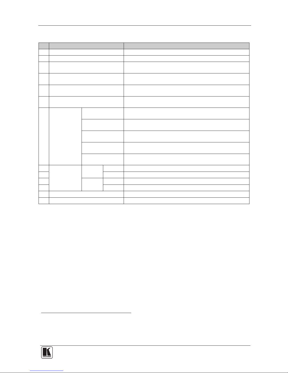
Table 2: Front Panel VP-26 Presentation Matrix Switcher Features
# Feature Function
1 IR (Infrared) Receiver Signals from the remote control transmitter illuminate the LED
2 POWER Switch Illuminated switch for turning the unit ON and OFF
3
VGA/UXGA-AUDIO SELECTOR
Buttons
Selects the VGA/UXGA video-audio source to switch to
OUT 1 and/or OUT 2 (from 1 to 4)
4
VIDEO (CV)-AUDIO SELECTOR
Buttons
Selects the composite video-audio source to switch to OUT 1
and/or OUT 2 (from 1 to 4)
5
s-VIDEO (Y/C)-AUDIO SELECTOR
Buttons
Selects the s-Video-audio source to switch to OUT 1 and/or
OUT 2 (from 1 to 4)
6 COMP-AUDIO SELECTOR Buttons Selects the component video-audio source to switch to OUT 1
and/or OUT 2 (input 1 and 2)
7
MASTER
AUDIO
SELECTOR
VGA/UXGA Button Press to route the selected audio signal (OUT 1 or OUT 2)
from the VGA/UXGA section to the master audio outputs
1
CV Button Press to route the selected audio signal (OUT 1 or OUT 2)
from the composite video section to the master audio outputs
1
s-VIDEO Button Press to route the selected audio signal (OUT 1 or OUT 2)
from the s-Video section to the master audio outputs
1
COMP. Button Press to route the selected audio signal (OUT 1 or OUT 2)
from the component video section to the master audio outputs
1
MIC Button Press to route the microphone input to the master audio
outputs
1
8
AUDIO LEVEL
MIC
+ Button Increase the microphone audio signal level
9 - Button Decrease the microphone audio signal level
10
MASTER
- Button Decrease the master audio signal level
11 + Button Increase the master audio signal level
12 LOCK Button Press to lock the front panel buttons
13 TALK OVER Button Push the button to activate talk over2
1 MASTER OUTPUT: LINE and SPEAKER
2 With the TALK OVER button pressed in, speaking into the microphone amplifies the voice of the speaker, overriding and
fading out all other audio channels. However, pressing the MIC button in the Master Audio Selector renders t he Talk Over
function inactive
Page 12
KRAMER: SIMPLE CREATIVE TECHNOLOGY
Your Presentation Matrix Switcher
8
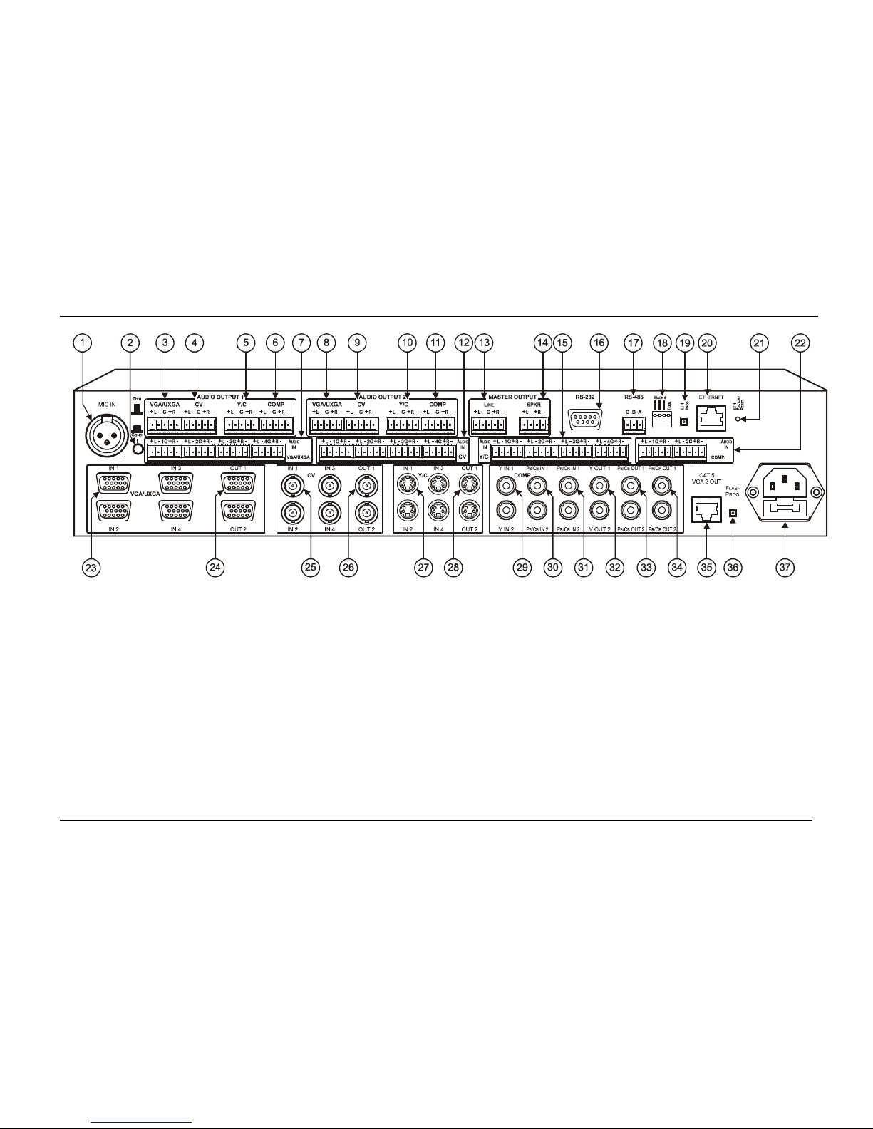
Figure 2: VP-26 Presentation Matrix Switcher – Rear View
Page 13
Your Presentation Matrix Switcher
9
Table 3: Rear Panel VP-26 Presentation Matrix Switcher Features
# Feature Function
1 MIC IN XLR Connector Connect to the microphone
2 COND. / DYN Selector Switch Push in to select a condenser, release to select a
dynamic microphone
3
AUDIO
OUTPUT 1
VGA/UXGA Terminal Block
Connector
Connect to a VGA/UXGA balanced audio acceptor
4 CV Terminal Block Connector Connect to a composite video balanced audio
acceptor
5 Y/C Terminal Block Connector Connect to an s-Video balanced audio acceptor
6 COMP Terminal Block
Connector
Connect to a component video balanced audio
acceptor
7 VGA/UXGA AUDIO IN Terminal Block
Connectors
Connect to the VGA/UXGA balanced audio sources1
8
AUDIO
OUTPUT 2
VGA/UXGA Terminal Block
Connector
Connect to a VGA/UXGA balanced audio acceptor
9 CV Terminal Block Connector Connect to a composite video balanced audio
acceptor
10 Y/C Terminal Block Connector Connect to an s-Video balanced audio acceptor
11 COMP Terminal Block
Connector
Connect to a component video balanced audio
acceptor
12 CV AUDIO IN Terminal Block Connectors Connect to the composite video balanced audio
sources
1
13
MASTER
OUTPUT
LINE Terminal Block Connector Connect the master balanced audio channel
acceptor
2
14 SPKR Terminal Block
Connector
Connect to a pair of loudspeakers
15 Y/C AUDIO IN Terminal Block Connectors Connect to the s-Video balanced audio sources1
16 RS-232 DB 9F Port Connects to the PC or the Remote Controller
17 RS-485 Terminal Block Port Pins B (- ) a n d A (+) are for RS-485; Pin G may be
connected to the shield (if required)
18 DIP-switches DIP-switches for setup of the unit (DIPs 1, 2 and 3
are for setting the machine # and DIP 4 is for RS-485
termination; see section 6.8
)
19 ETH PROG Button Press to upgrade the Ethernet microcontroller
firmware (see section 8.2
)
20 ETHERNET Connector Connects to the PC or other Serial Controll er through
computer networking
21 ETH Factory Reset Button Press to reset to factory default definitions3:
IP Address: 192.168.1.39
Mask: 255.255.255.0
Gateway: 192.168.1.1
1 From 1 to 4
2 Both the LINE and the SPKR terminal block connecters receive the same signal: the LINE outputs it as it is while the SPKR
is amplified
3 Turn the machine OFF using the power switch and then turn it ON while pressing the ETH Factor y Reset button. The unit
will power up and load its memory with the factory default definitions
Page 14
KRAMER: SIMPLE CREATIVE TECHNOLOGY
Your Presentation Matrix Switcher
10
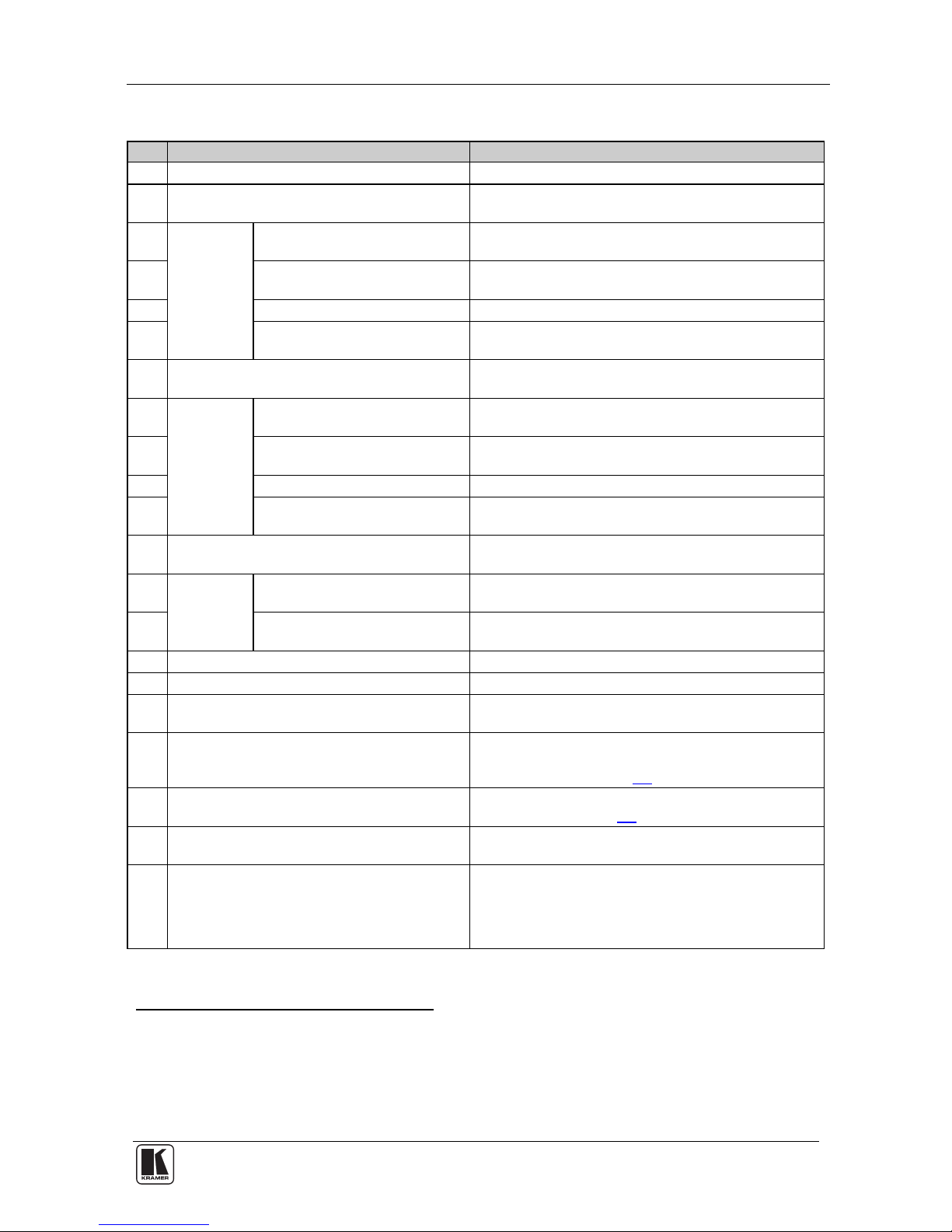
# Feature Function
22 COMP AUDIO IN Terminal Block Connectors Connect to the component video balanced audio sources1
23
VGA/UXGA
IN HD15 Connectors Connect to the VGA/UXGA video sources2
24 OUT HD15 Connectors Connect to the VGA/UXGA video acceptors1
25
CV
IN BNC Connectors Connect to the composite video sources2
26 OUT BNC Connectors Connect to the composite video acceptors1
27
Y/C
IN 4-pin Connectors Connect to the s-Video sources2
28 OUT 4-pin Connectors Connect to the s-Video acceptors1
29
COMP
Y IN RCA Connectors
Connect to the component (Y, P
B/CB, PR/CR) video
sources (1 and 2)
30 PB/CB IN RCA Connectors
31 PR/CR IN RCA Connectors
32 Y OUT RCA OUT Connectors Connect to the component (Y, PB/CB, PR/CR) video
acceptors (1 and 2)
33 PB/CB OUT RCA Connectors
34 PR/CR OUT RCA Connectors
35
CAT 5 VGA 2 OUT
3
Twisted Pair Connector
Connect to a remote computer graphics acceptor via
a receiver (for example, the TP-122
4
)
36 FLASH PROG. Button Push in for “Program” to upgrade to the latest Kramer
firmware (see section 8), or release for Normal (the
factory
default)
37 Power Connector with Fuse AC connector enabling power supply to the unit
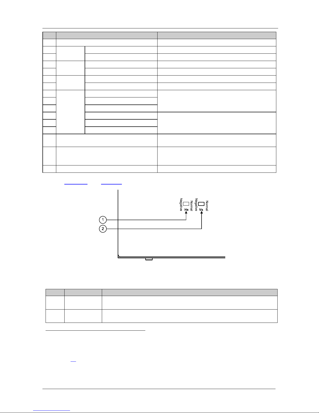
Figure 3 and Table 4 define the VP-26 unde rside features:
Figure 3: VP-26 Presentation Switcher / Controller – Underside View
Table 4: VP-26 Underside Panel Features
# Feature Function
1 HS Switch Slide the switch to the right (to NORMAL) to retain the polarity
Slide the switch to the left
5
to change the HS polarity to NEGATIVE polarity6
2 VS Switch Slide the switch to the right (to NORMAL) to retain the polarity
Slide the switch to the left
5
to change the VS polarity to NEGATIVE polarity6
1 From 1 to 2
2 From 1 to 4
3 The CAT5 outputs the VGA/UXGA OUT 2 signal only
4 See section 6.1
5 By default, both switches are set to the right
6 Downgoing syncs
Page 15

Installing the VP-26 on a Rack
11
5 Installing the VP-26 on a Rack
This section describes what to do before installing on a rack and how to rack
mount.
Before Installing in a rack
How to Rack Mount
Before installing in a rack, be sure that the environment is
within the recommended range:
To rack-mount a machine:
1. Attach both ear brackets to the
machine. To do so, remove the
screws from each side of the
machine (3 on each side), and
replace those screws through the
ear brackets.
2. Place the ears of the machine
against the rack rails, and insert the
proper screws (not provided)
through each of the four holes in the
rack ears.
Note that:
• In some models, the front panel
may feature built-in rack ears
• Detachable rack ears can be
removed for desktop use
• Always mount the machine in the
rack before you attach any cables
or connect the machine to the
power
• If you are using a Kramer rack
adapter kit (for a machine that is not
19"), see the Rack Adapters user
manual for installation instructions
(you can download it at:
http://www.kramerelectronics.com)
Operating temperature range +5° to +45° C (41° to 113° F)
Operating humidity range 10 to 90% RHL, non-condensing
Storage temperature range -20° to +70° C (-4° to 158° F)
Storage humidity range 5 to 95% RHL, non-condensing
!
CAUTION!!
When installing on a 19" rack, avoid hazards by taking
care that:
1. It is located within the recommended environmental
conditions, as the operating ambient temperature of a
closed or multi unit rack assembly may exceed the
room ambient temperature.
2. Once rack mounted, enough air will still flow around
the machine.
3. The machine is placed straight in the correct
horizontal position.
4. You do not overload the circuit(s). When connecting
the machine to the supply circuit, overloading the
circuits might have a detrimental effect on overcurrent
protection and supply wiring. Refer to the appropriate
nameplate ratings for information. For example, for
fuse replacement, see the value printed on the
product label.
5. The machine is earthed (grounded) in a reliable way
and is connected only to an electricity socket with
grounding. Pay particular attention to situations where
electricity is supplied indirectly (when the power cord
is not plugged directly into the socket in the wall), for
example, when using an extension cable or a power
strip, and that you use only the power cord that is
supplied wi th the machin e.
Page 16

KRAMER: SIMPLE CREATIVE TECHNOLOGY
Connecting the VP-26 Presentation Matrix Switcher
12
6 Connecting the VP-26 Presentation Matrix Switcher
This section describes how to:
• Connect the rear panel (see section 6.1
)
• Connect the audio (see section 6.2
)
• Wire the CAT 5 connector (see section 6.3
)
• Connect a PC or other controller via the RS-232 port (see section
6.4
)
• Connect a controller via the RS-485 port (see section 6.5
)
• Control via the ETHERNET (see section 6.6
)
• Cascade several machines (see section 6.7
)
• Set the DIP-switches (see section 6.8
)
6.1 Connecting the VP-26 Rear Panel
To c
onnect
1
the VP-26, as the example2 illustrated in Figure 4 shows3, do
the following
4
:
1. Connect the following video s ources, that is , one
5
:
VGA/UXGA source (for example, a computer graphics source)
to the VGA/UXGA IN 1 15-pin HD (F) connector
Composite video source (for example, a composite video
player) to the CV IN 1 BNC connector
s-Video source (for example, an s-Video player) to the Y/C IN
1 4-pin connector
Component video source (for example, a DVD player) to the
three IN 1 RCA connectors Y, Pb/Cb and Pr/Cr
2. Connect the OUT 1 acceptors to a projector
6
as follows:
The composite video CV OUT BNC connector to the
composite video input of the projector
The s-Video Y/C OUT 4-pin connector to the s-Video input of
1 You do not need to connect all the inputs
2 In this example, each of the OUT 1 connectors (one from each grou p) is connected to the same projector. Use the projecto r
controller to switch between the VP-26 video outputs (or projector inputs)
3
In Figure 4, the audio connections are not shown, except for the microphone and speakers connections
4 Switch OFF the power on each device before connecting it to your VP-26. After connecting your VP-26, switch on its
power and then switch on the power on each device. Switching on the VP-26, recalls th e previous setu p from the n on-volatil e
memory
5 Although in this example only one source is connected, you can connect all four inputs, that is, 12 in total
6 In this example a projector is used, but you can also connect separate outputs such as displays, video recorders and so on
Page 17

Connecting the VP-26 Presentation Matrix Switcher
13
the projector
The VGA/UXGA UXGA OUT 15-pin HD (F) connector to the
VGA/UXGA input of the projector
The three OUT RCA connectors Y, P
B/CB and PR/CR to the
component video input of the projector
3. Connect the appropriate balanced audio sources and accept ors (not shown in
Figure 4
1
).
4. Connect the MASTER OUTPUT LINE terminal block connector, if
required (not show n in Figure 4
; see section 7.3).
5. Connect the MASTER OUTPUT SPKR block connector to a pair of
loudspeakers, by connecting the left loudspeaker to the “L+” and the “L-”
terminal block connectors, and the right loudspe aker to the “R+” and the
“R-” terminal block connectors. Do not Ground the loudspeakers .
6. Connect the CAT 5 VGA 2 OUT twisted pair connector (see section 6.3
) to
a line receiver (for example, the TP-122 XGA / Audi o Line Receiver
2
,
which is connected to a remote display and speakers).
7. Connect a dynamic or a conde nser microp hone
3
, if required, to the MIC IN
XLR connector.
8. You can connect a PC and/ or control ler to the:
RS-232 port (see section 6.4
)
RS-485 port (see section 6.5
)
ETHERNET (see section 6.6
)
9. Connect the unit to additional machines (if required) via the RS-485 port
(see section 6.7
) for control.
10. Connect the power cord.
1 In Figure 4, the audio connections are not shown, except for the microphone and speakers connections
2 The receiver receives the CAT5 signal, decodes it and outputs it to a VGA acceptor
3 Use the Con/Dyn switch (refer to the rear panel, item 2 in Figure 2
) to select a dynamic microphone or a condenser
Page 18

KRAMER: SIMPLE CREATIVE TECHNOLOGY
Connecting the VP-26 Presentation Matrix Switcher
14
Figure 4: Connecting the VP-26 Presentation Matrix Switcher
Page 19

Connecting the VP-26 Presentation Matrix Switcher
15
6.2 Connecting the Balanced/Unbalance d Stereo Audio Input/Ou tput
Figure 5
, Figure 6, and Figure 7 illustrate how to wire a balanced /
unbalanced input and/or output connection:
L R
+ - G + -
L R
+ - G + -
L
R
+ - G + -
Figure 5: Connecting a
Balanced Stereo Audio
Input/Output
Figure 6: Connecting an
Unbalanced Stereo Audio
Input
Figure 7: Connecting an
Unbalanced Stereo Audio
Output
6.3 Wiring the CAT 5 LINE OUT RJ-45 Connector
Table 5
and Figure 8 define the CAT 5 PINOUT, using a straight pin-to-pin
cable with RJ-45 connectors:
Table 5: CAT 5 PINOUT
Figure 8: CAT 5 PINOUT
EIA /TIA 56 8A EIA /TIA 568B
PIN Wire Color PIN Wire Color
1 Green / White 1 Orange / White
2 Green 2 Orange
3 Orange / White 3 Green / White
4 Blue 4 Blue
5 Blue / White 5 Blue / White
6 Orange 6 Green
7 Brown / White 7 Brown / Whi te
8 Brown 8 Brown
Pair 1 4 and 5 Pair 1 4 and 5
Pair 2 3 and 6 Pair 2 1 and 2
Pair 3 1 and 2 Pair 3 3 and 6
Pair 4 7 and 8 Pair 4 7 and 8
Page 20

KRAMER: SIMPLE CREATIVE TECHNOLOGY
Connecting the VP-26 Presentation Matrix Switcher
16
6.4 Connecting a PC
You can connect a PC (or other controller) to the VP-26 vi a the RS-232 po rt.
To connect using the null-modem adapter provided with the machine
(recommended method):
• Connect the RS-232 9-pin D-sub rear panel port on the VP-26 to
the null-modem adapter and connect the null-modem adapter with a
9-wire flat cable to the RS-232 9-pin D-sub port on your PC
To connect without using a null-modem adapter:
• Connect the RS-232 9-pin D-sub port on your PC to the RS-232
9-pin D-sub rear panel port on the VP-26, as Figure 9
illustrates
Female 9-pin D-su b (From PC)
PI N 4 Conne c ted to PI N 6
P INS 8, 7, 1 Connected together
If a Shie lde d cable i s used , con nect the shield to P IN 5
PIN 5 Connected to PIN 5 (Ground)
PIN 3 Conne cted to PI N 2
PIN 2 Conne cted to PI N 3
Male 9-pin D-sub
Figure 9: Connecting a PC Without a null-modem Adapter
6.5 Connecting via RS-485
You can control a VP-26 unit via an RS-485 controller, or a Master
Programmable Remote Control system such as the Kramer RC-3000.
To connect an RC-3000 to a VP-26 unit (see Figure 10
), connect the
RS-485 terminal block port on the RC-3000 to the RS-485 port on the
VP-26 unit, as follows:
• Connect the “A” (+) PIN on the RS-485 rear panel port of t he
RC-3000 to the “A” (+) PIN on the RS-485 rear panel port of the
VP-26 unit
• Connect the “B” (-) PIN on the RS-485 rear panel port of the
RC-3000 to the “B” (-) PIN on the RS-485 rear panel port of the
VP-26 unit
• If shielded twisted pair cable is used, the shield may be connected
to the “G” (Ground) PIN on one of the units (for example, on the
RC-3000)
Page 21

Connecting the VP-26 Presentation Matrix Switcher
17
• Set the VP-26 unit to a Machine # other than 1, according to Table
7, and set DIP 4 ON (for RS-485 line termination with 120Ω)
KEYBOARD EXTENSION REMOTE CONTACT
RS-485 RS-232 IN RS-232 OUT
12 VDC
12 12345 678G468103 5 7 9 11 12 14 16
OUT
13 15
IN
RC-3000
RS-485 PINOUT
G
B
A
_
+
Figure 10: Controlling via RS-485 (for example, using an RC-3000)
6.6 Controlling via ETHERNET
You can connect the VP-26 via the Ethernet, using a crossover cable (see
section 6.6.1
) for direct connection to the PC or a straight through cable (see
section 6.6.2
) for connection via a network hub or netw or k rout er1.
6.6.1 Connecting the ETHERNET Port Directly to a PC (Crossover Cable)
You can connect the Ethernet port of the VP-26 to the Ethernet port on your
PC, via a crossover cable with RJ-45 connectors.
This type of connection is recommended for identification of the factory default
IP Address of the VP-26 during the initial configuration
After connecting the Ethernet port, configure your PC as follows:
1. Right-click the My Network Places icon on your desktop.
1 After connecting the Ethernet port, you have to install and configure your Ethernet Port. For detailed instructions, see the
“Ethernet Configuration (FC-11) guide.pdf” file in the technical support section on our Web site:
http://www.kramerelectronics.com
Page 22

KRAMER: SIMPLE CREATIVE TECHNOLOGY
Connecting the VP-26 Presentation Matrix Switcher
18
2. Select Properties.
3. Right-click Local Area Connection Properties.
4. Select Properties.
The Local Area Connection Properties window appears.
5. Select the Internet Protocol (TCP/IP) and click t he Properties Button (see
Figure 11
).
Figure 11: Local Area Connection Properties Window
6. Select Use the following IP Address, and fill in the details as shown in
Figure 12
.
7. Click OK.
Figure 12: Internet Protocol (TCP/IP) Properties Window
Page 23

Connecting the VP-26 Presentation Matrix Switcher
19
6.6.2 Connecting the ETHERNET Port via a Network Hub (Straight-Through
Cable)
You can connect the Ethernet port of the VP-26 to the Ethernet port on a
network hub or network router, via a straight-through cable with RJ-45
connectors.
6.6.3 Control Configuration via the Ethernet Port
To control several units via the Ethernet, connect the Master unit
(Machine # 1) via the Ethernet port to the LAN port of your PC. Us e your
PC initially to configure the settings (see section 6.6
).
6.7 Controlling via RS-232 and RS-485
Yo
u can cascade up to eight VP-26 units with control from a PC or serial
controller.
To cascade up to eight individual VP-26 units, via RS-232 and RS-485, as
illustrated in Figure 13
, do the following:
1. Connect the video sources and acce ptors, as well as the appropriate audio
sources and acceptors, as descri bed in section 6.1
.
2. Connect the RS-232 port on the first VP-26 unit to the PC using the nullmodem adapter provided with the machine (recommended), as section 6.4
describes.
3. Connect the RS-485 terminal block port on the first VP-26 unit to the
RS-485 port on the second VP-26 unit and so on, connecting all the RS-485
ports.
4. Set the DIP-switches, as section 6.8.1
describes. In particular:
Set the first VP-26 unit as Machine # 1, the second unit to
Machine # 2, and so on - up to Machine # 8 for the eighth
unit
Set Dip 4 ON on the first and last VP-26 units (terminating
the RS-485 line at 120Ω). On the other units, set DIP 4 OFF
Page 24

KRAMER: SIMPLE CREATIVE TECHNOLOGY
Connecting the VP-26 Presentation Matrix Switcher
20
Machine # 1 (Master)
Machine # 2
Machine # 8
Up to 8
Units
Figure 13: Control Configuration via RS-232 and RS-485
Page 25

Connecting the VP-26 Presentation Matrix Switcher
21
6.8 DIP-Switch Settings
Figure 14
and Table 6 define the factory default DIP-switch settings1:
OFF
ON
1234
Figure 14: Default DIP-switch Settings
Table 6: DIP-switch Settings
DIPS Function Description
1, 2, 3 Machine # Determines the number of the machine in the sequence
4 RS-485 TERM
ON for RS-485 Line Termination with 120Ω;
OFF for no RS-485 Line Termination
6.8.1 Setting the Machine # DIP-Switches
You can cascade up to eight VP-26 units. The Machine # determines the
position of a VP-26 unit, specifying which VP-26 unit is being controlled
when several VP-26 units connect to a PC or serial controller. Set the
Machine # on a VP-26 unit via Setup DIPS 1, 2 and 3, according to Table 7
.
Table 7: Machine # DIP-switch Settings
Machine
#
DIP-switch
1 2 3
1
Maste
r
OFF OFF OFF
2 OFF OFF ON
3 OFF ON OFF
4 OFF ON ON
5 ON OFF OFF
6 ON OFF ON
7 ON ON OFF
8 ON ON ON
1 By default, all dipswitches are set to OFF
Page 26

KRAMER: SIMPLE CREATIVE TECHNOLOGY
Operating Your Switcher
22
7 Operating Your Switcher
This section describes the:
• Front panel buttons (see section 7.1
)
• Independent switchers AFV mode (see section 7.2
)
• Master audio breakaway mode (see section 7.3
)
7.1 The Front Panel Buttons
Th
e front panel buttons include:
• Two sets of four (from 1 to 4) VGA/UXGA-AUDIO SELECTOR
buttons for switching to OUT 1 and/or OUT 2
• Two sets of four (from 1 to 4) VIDEO (CV)-AUDIO SELECTOR
buttons for switching OUT 1 and/or OUT 2
• Two sets of four (from 1 to 4)
S-VIDEO (Y/C)-AUDIO
SELECTOR buttons for switching to OUT 1 and/or OUT 2
• Two sets of two (1 and 2) COMP-AUDIO SELECTOR buttons for
switching to OUT 1 and/or OUT 2
• Nine MASTER AUDIO SELECTOR buttons (two sets of
VGA/UXGA, CV,
S-VIDEO and COMP for OUT 1 and OUT 2
signals, and MIC)
• MIC AUDIO LEVEL up and down buttons to adjust the level at
the master audio out
1
connectors2 and the talk-over function
threshold
3
• MASTER AUDIO LEVEL up and down buttons to adjust the
audio output level at the master audio out connectors
1
, without
influencing any other audio output
• Panel LOCK button to lock the front panel buttons
• TALK OVER button
4
, which lowers or mutes the MASTER
AUDIO LEVEL when the microphone picks up speech
5
1 MASTER OUT and SPKR OUT
2 Useful in the TALK OVER mode, when the microphone level needs to be adjusted separately
3 Achieving optimum results for a particular environment when using a microphone ma y require experi mentatio n in adjusti n g
the AUDIO and MIC LEVELS
4 Two channels are active in the Talk Over mode, a source selected via the MASTER AUDIO SELECTOR buttons and the
microphone channel
5 Adjust the microphone level via the MIC AUDIO LEVEL + and - buttons
Page 27

Operating Your Switcher
23
By default1, the stereo audio signals switch together with the video, that is, the
unit is set in an AFV 2 mode. You can change to breakaway mode3, via RS-232
Pressing an illuminated AUDIO SELECTOR button for more than 2
seconds mutes the master audio output, and the button no longer
illuminates. The video will continue to display but without sound.
7.2 The Independent Switchers AFV Mode
In th
e independent switchers AFV mode, the four matrix switchers of the
VP-26 operate independently of each other. For each matrix switcher, you
can select any input to switch to the outputs, as illustrated in Figure 15
.
The audio input signal follows the video signal and the last audio signal
selected is outputted to the master audio output
You can route any combination of:
• Two of the four VGA/UXGA inputs to the VGA/UXGA
4
outputs
• Two of the four CV inputs to the CV outputs
• Two of the four Y/C inputs to the Y/C outputs
• The COMP inputs to the COMP outputs
For example
5
, in the CV matrix switcher section, you can switch IN 1 to
OUT 1 and IN 4 to OUT 2 by pressing the VIDEO (CV)-AUDIO
SELECTOR button 1 on the OUT 1 set, and button 4 on the OUT 2 set.
The same applies to the other matrix switcher sections (CV, Y/C and
COMP).
Each pressed button illuminates
6
, indicating selection and outputting of that
video and audio source.
You can choose not to use one or more of the matrix switchers
1 This is, the pre-installed factory default. The default can be modified via the Windows®-based Kramer control software
2 Audio-Follow-Video, in which all operations relate to both the video and the audio channels
3 In which video and audio channels switch independently
4 The OUT 2 signal is also routed to the CAT5 VGA 2 OUT connector
5 Assuming that all inputs are connected
6 Pressing an illuminated button for more than 2 seconds will disconnect the output and the button will no longer illuminate
Page 28

KRAMER: SIMPLE CREATIVE TECHNOLOGY
Operating Your Switcher
24
s-Video Sources
Comp. video Sources
Comp. video
Acceptors
S-VHS
S-VHS
S-VHS
S-VHS
s-Video Acceptors
S-VHS
S-VHS
Video Acceptors
CV Video Sources
UXGA Sources
UXGA Ac ceptors
Speakers
Figure 15: Independent Switchers Mode
Page 29

Operating Your Switcher
25
7.3 The Master Audio Breakaway Mode
The Master Audio automatically follows the last input selected
1
(for example,
COMP OUT 1 in Figure 15
), regardless of the switcher group (VGA, s-Video,
composite video or component video), and the respective button
2
under the
MASTER AUDIO SELECTOR section illuminates, indicating that the selected
input (for example, COMP OUT 1 in Figure 15
) is routed to the master outputs.
In the Master Audio Breaka way mode
3
, switching a video input will not switch
the respective audio si gnal. You ca n indepe ndently ro ute an au dio input si gnal
from any of the A/V matrix switchers or from the microph one, to the MASTER
OUTPUT LINE
4
and/or SPKR4 outputs, regardl ess of the vide o input l ast
selected. You can change the audio input switched to the master output by
pressing the relevant button under the MASTER AUDIO SELECTOR
section
5
. For example, press the CV OUT 2 button under the MASTER
AUDIO SELECTOR section to route the composite video input 4 signal to
the MASTER OUTPUT, as illustrated in Figure 16
:
Figure 16: Switching in the Master Audio Mode
When a microphone is connected to the MIC IN XLR connector, you can
press the MIC button under the MASTER AUDIO SELECTOR section.
The MIC button illuminates (see Figure 17
) and the speakers output the
MIC IN
6
audio signal, while retaining the current video display. You can
return to the composite video (CV) audio output by pressing the relevant
CV button under the MASTER AUDIO SELECTOR section once again.
Figure 17: Switching to the MIC in the Master Audio Mode
1 The Independent Switchers AFV mode
2 Replacing the previous illuminated button
3 You can set the machine to the breakaway mode via RS-232
4 The MASTER audio signal is routed simultaneousl y to the LINE and the SPKR channels. The only difference between
them is that the SPKR channel has an internal power amplifier, which lets you connect the speakers directly to the unit
5 The nine MASTER AUDIO SELECTOR buttons include one button for each of the outputs and the MIC button
6 Another way to use the microphone is to press the TALK OVER button:
the main audio level is lowered when the
microphone picks up speech
Page 30

KRAMER: SIMPLE CREATIVE TECHNOLOGY
Flash Memory Upgrade
26
8 Flash Memory Upgrade
The VP-26 lets you upgrade both the:
• Switcher Microcontroller (see section 8.1
)
• Ethernet Microcontroller (see section 8.2
)
8.1 Switcher Flash Memory Upgrade
The VP
-26 firmware is located in FLASH memory, which lets you upgrade
to the latest Kramer firmware version in minutes! The process involves:
• Downloading from the Internet (see section 8.1.1
)
• Connecting the PC to the RS-232 port (see section 8.1.2
)
• Upgrading Firmware (see section 8.1.3
)
8.1.1 Downloading from the Internet
You can download the up-to-date file1 from the Internet. To do so:
1. Go to our Web site at http://www.kramerelectronics.com and download the
file: “FLIP_VP26.zip” from the Technical Support section.
2. Extract the file: “FLIP_VP26.zip” to a folder (for example, C:\Program
Files\Kramer Flash).
3. Create a shortcut on your desktop to the file: “FLIP.EXE”.
8.1.2 Connecting the PC to the RS-232 Port
Before installing the latest Kramer firmware version on a VP-26 unit, do the
following:
1. Connect the RS-232 9-pin D-sub rear panel port on the VP-26 unit to the
null-modem adapter and connect the null-modem adapter with a 9-wire flat
cable to the RS-232 9-pin D-sub COM port on your PC (see section 6.4
).
2. On the rear panel, push in the FLASH PROG. button (to program), using a
screwdriver.
3. Connect the power on the VP-26 unit and switch it ON.
4. On the rear panel, push in the FLASH PROG. (see Figure 2
), using a
screwdriver.
1 The files indicated in this section are given as an example only. These file names are liable to change from time to time
Page 31

Flash Memory Upgrade
27
8.1.3 Upgrading Firmware
Follow these steps to upgrade the firmware:
1. Double click the deskt op icon: “ Shortc ut to FLIP.EXE”.
The Splash screen appears as follows:
Figure 18: Splash Screen
2. After a few seconds, the Splash screen is replaced by the “Atmel – Flip”
window:
Figure 19: Atmel – Flip Window
3. Press the keyboard shortcut key F2 (or select the “Select” command from
the Device menu, or press the in tegrated circui t icon in t he upper rig ht
corner of the window).
The “Device Selection” window appears:
Page 32

KRAMER: SIMPLE CREATIVE TECHNOLOGY
Flash Memory Upgrade
28
Figure 20: Device Selection Window
4. Click the button next to the name of the device and select from the list:
AT89C51RD2:
AT89C51RD2
T89C51RD2
Figure 21: Selecting the Device from the Selection Window
5. Click OK and select “Load Hex” from the File menu.
Page 33

Flash Memory Upgrade
29
A
Figure 22: Loading the Hex
6. The Open File window opens. Select the correct HEX file that contains the
updated version of the firmware for VP-26 (for example, 26M_V 1p2.hex)
and click Open.
7. Press the keyboard shortcut key F3 (or select the “Communication / RS232”
command from the Settings menu, or press the keys: Alt SCR).
The “RS232” window appears. Change t he COM port acc ording to the
configuration of your computer and select the 9600 baud rate:
Figure 23: RS-232 Window
8. Click Connect.
In the “Atmel – Flip” window, in the Operations Flow column, the Run
button is active, and the name of the chip appears as the name of the third
column: AT89C51RD2.
Page 34

KRAMER: SIMPLE CREATIVE TECHNOLOGY
Flash Memory Upgrade
30
Verify that in the Buffer Information column, the “HEX File: VP26.hex”
appears.
A
VP26.hex
Figure 24: Atmel – Flip Window (Connected)
9. Click Run.
After each stage of the operation is completed, the check-box for that stage
becomes colored green
1
.
When the operation is completed, all 4 check-boxes will be colored green
and the status bar message: Memory Verify Pass appears
2
:
1 See also the blue progress indicator on the status bar
2 If an error message: “Not Finished” shows, click Run again
Page 35

Flash Memory Upgrade
31
VP26.he
x
A
Figure 25: Atmel – Flip Window (Operation Completed)
10. Close the “Atmel – Flip” window.
11. Disconnect the power on the VP-26.
12. Disconnect the RS-232 rear panel port on the VP-26 unit from the null-
modem adapter.
13. Release the FLASH PROG . button on rear pan el.
14. Connect the power to the VP-26.
8.2 Ethernet Flash Memory Upgrade
The VP
-26 firmware is located in FLASH memory, which lets you upgrade
to the latest Kramer firmware version in minutes!
The process involves:
• Downloading the upgrade packag e from the Internet
• Connecting the PC to the RS-232 port
• Upgrading the firmware
Page 36

KRAMER: SIMPLE CREATIVE TECHNOLOGY
Flash Memory Upgrade
32
8.2.1 Downloading from the Internet
You can download the up-to-date file1 from the Internet. To do so:
1. Go to our Web site at http://www.Kramerelectronics.com and download the
file: “SetKFRET
H11-xx.zip”
from the technical support section.
2. Extract the file “SetKFRETH11-xx.zip”
package, which includes the
KFR-Programmer application setup and the .s19 firmware file, to a folder
(for example, C:\Program Files\KFR Upgrade).
3. Install the KFR-Programmer Application.
8.2.2 Connecting the PC to the RS-232 Port
Before installing the latest Kramer Ethernet firmware version on the VP-26,
do the following:
1. Connect the RS-232 9-pin D-sub port (C OM 1) on the VP-26 t o a null-
modem adapter and connect the null-mode m adapter with a 9-wire flat cable
to the RS-232 9-pin D-sub COM port on your PC.
2. Push in the ETH PROG button, located on the machine rear side.
3. Connect the power on your machine.
8.2.3 Upgrading Firmware
Follow these steps to upgrade the firmware:
1. Double click the KFR-Programmer desktop icon.
The KFR-Programmer window appears (see Figure 26
).
Figure 26: The KFR-Programmer Window
1 File names are liable to change from time to time
Page 37

Flash Memory Upgrade
33
2. Select the required COM Port1.
3. Press the File button to select the .s19 firmware file included in the package.
4. Press the Send button to download the file. The Send button lights red.
5. Wait until downloading is completed and the red Send button turns off.
6. Disconnect the power on the VP-26.
7. Release the ETH PROG button, located on the machine rear side.
8. Connect the power on your machine.
1 To which the VP-26 is connected on your PC
Page 38

KRAMER: SIMPLE CREATIVE TECHNOLOGY
Technical Specifications
34
9 Technical Specifications
Table 8 includes the technical specifications1:
Table 8: Technical Specifications of the VP-26 Presentation Switcher
INPUTS: 4 VGA/UXGA on 15-pin HD (F) connecto rs
4 s-Video, 1 Vpp (Y), 0.3Vpp (C) / 75 Ω on 4-pin connectors
4 composite video 1Vpp / 75 Ω on BNC connectors
2 sets of component video (Y, Pb/Cb, Pr/Cr) 1Vpp, 0.7Vpp, 0.7Vpp on RCA connectors
Each input is accompanied by the appropriate balanced stereo-audio channels: +4dBm /
50 kΩ on detachabl e termina l block conn ectors
Mic: 3mV / 10 kΩ condenser / dynamic on an XLR connector
OUTPUTS: 2 VGA/UXGA on 15-pin HD (F) connecto rs
2 s-Video - 1 Vpp (Y), 0.3Vpp (C), / 75 Ω on 4-pin connectors
2 composite video 1 Vpp / 75 Ω on BNC connectors
2 sets of component video (Y, Pb/Cb, Pr/Cr) 1Vpp, 0.7Vpp, 0.7Vpp on RCA connectors
1 UTP CAT 5 connector (Line OUT)
Each output is accompanied by the appropriate balanced stereo-audio channel: +4dBm
/ 150 Ω on detachable terminal blocks
1 master stereo audio +4dBm / 150 Ω on a detachable te rminal blo ck
1 stereo speaker output 2x5 W continuo us into 4Ω
MAX. OUTPUT LEVEL: Video: VGA/UXGA: 2.85Vpp;
Y/C: 2.8Vpp; CV: 3.8Vpp;
Component video 2.7Vpp;
CAT 5: 2Vpp
Audio: Group: 20dBm
Master: 15dBm
BANDWIDTH (-3dB): Video: VGA/UXGA: 300MHz;
Y/C : 3 20MHz; CV: 420MHz; Component
video: 380MHz; CAT 5: up t o UXGA
Audio: Group: 46kHz
Speakers: 40kHz
Master: 33kHz
DIFF. GAIN: VGA /UXGA: 0.15%; Y/C: 0.03%; CV: 0.03%; CAT 5: 6.4%
DIFF. PHASE: VGA /UXGA: 0.09 Deg; .Y/C: 0.03 Deg.; CV: 0.03 Deg.; CAT 5: 0.2 Deg.
K-FACTOR: <0.1%
S/N RATIO: Video: VGA/UXGA: 75dB
Y/C: 81dB; CV: 75dB;
Component video: 76dB;
CAT 5: 59dB; (unw eighte d)
Audio: Group: 74dB
Speakers: 53dB (max pwr weighted)
Master out: 72dB
CROSSTALK (all hostile): Video: VGA/UXGA: -45dB;
Y/C: -48dB; CV: -41dB;
Component video: -43dB
Audio: Group: < -76dB
Master: < -69dB @1kHz
CONTROLS: Channel selector for v ideo and aud io, for VG A/UXGA, Y /C and CV; master au dio outpu t
selector, master audio level, mic audio level, talkover, lo ck, R S-232, R S-48 5, Eth ernet,
IR
COUPLING: Video: VGA/UXGA, Y/C and CV: DC Audio: AC, input and output
AUDIO THD +
NOISE@1kHz:
Group: 0.08%; Speakers: 2% (max pwr); Master: 0.25%
AUDIO 2nd HARMONIC: Group: 0.065%; Speakers: 1.6% (max pwr); Master: 0.155%
POWER SOURCE: 100 - 264VAC, 50/60Hz, 37VA
DIMENSIONS: 19" x 7" x 2 U W, D, H
WEIGHT: 3.8kg (8.4lbs) approx.
ACCESSORIES: Power cord, null-modem adapter, Windows®-based Kramer control software,
Windows®-based Ethernet Configuration Manager and Virtual Serial Port Manager,
infrared remote control transmitter
1 Specifications are subject to change without notice
Page 39

Hex Table
35
10 Hex Table
Table 9 and Table 10 list the Hex values (which the protocol in section 11
describes in more detail) for the VP-26 Presentation Switcher. RS-232
communication is at 9600 baud, no parity, 8 data bits and 1 stop bit.
Table 9: VP-26 Hex Table Video and Audio In-group IN-OUT 1 Selector
Inputs VGA OUT 1 Composite
Video OUT 1
s-Video OUT 1 Component
Video OUT 1
Group #
VGA
In 1 01 81 81 81
In 2 01 82 81 81
In 3 01 83 81 81
In 4 01 84 81 81
Composite
Video
In 1
01 81 82 81
In 2 01 82 82 81
In 3 01 83 82 81
In 4 01 84 82 81
s-Video
In 1
01 81 83 81
In 2 01 82 83 81
In 3 01 83 83 81
In 4 01 84 83 81
Component
Video
In 1 01 81 84 81
In 2 01 82 84 81
Table 10: VP-26 Hex Table Video and Audio In-group IN-OUT 2 Selector
Inputs VGA OUT 2 Composite
Video OUT 2
s-Video
OUT 2
Component
Video OUT 2
Group #
VGA
In 1 01 81 85 81
In 2 01 82 85 81
In 3 01 83 85 81
In 4 01 84 85 81
Composite
Video
In 1
01 81 86 81
In 2 01 82 86 81
In 3 01 83 86 81
In 4 01 84 86 81
s-Video
In 1
01 81 87 81
In 2 01 82 87 81
In 3 01 83 87 81
In 4 01 84 87 81
Component
Video
In 1 01 81 88 81
In 2 01 82 88 81
Page 40
KRAMER: SIMPLE CREATIVE TECHNOLOGY
Hex Table
36
Table 11: VP-26 Master Audio Selector Hex Table
Master Audio Selector (Group Audio OUT) Audio Master OUT
VGA Audio OUT 1 02 81 81 81
Composite Video Group Audi o OUT 1 02 82 81 81
s-Video Group Audio OUT 1 02 83 81 81
Component Video Group Audio OUT 1 02 84 81 81
VGA Audio OUT 2 02 85 81 81
Composite Video Group Audi o OUT 2 02 86 81 81
s-Video Group Audio OUT 2 02 87 81 81
Component Video Group Audio OUT 2 02 88 81 81
Microphone 02 8A 81 81
Disconnect All 02 80 81 81
10.1 Audio Gain Control Hex Tables
The following tables describe the audio gain controls.
Table 12: Set the Audio OUT 1 Gain Control for the Groups
Audio Gain Control for Groups
VGA 1 Composite Video 1 s-Video 1 Composite Video 1
Notes
16 81 80 81 16 82 80 81 16 83 80 81 16 84 80 81 Mute
…
…
…
…
16 81 EC 81 16 82 EC 81 16 83 EC 81 16 84 EC 81 0dB (1:1)
…
…
…
…
16 81 FF 81 16 82 FF 81 16 83 FF 81 16 84 FF 81 9dB
Table 13: Set the Audio OUT 2 Gain Control for the Groups
Audio Gain Control for Groups
VGA 2 Composite Video 2 s-Video 2 Composite Video 2
Notes
16 85 80 81 16 86 80 81 16 87 80 81 16 88 80 81 Mute
…
…
…
…
16 85 EC 81 16 86 EC 81 16 87 EC 81 16 88 EC 81 0dB (1:1)
…
…
…
…
16 85 FF 81 16 86 FF 81 16 87 FF 81 16 88 FF 81 9dB
Table 14: Set the Audio Output Gain Control for the Microphone
Audio Gain Control for Microphone
16 8A 80 81 Mute
…
16 8A CD 81
…
16 8A FF 81 Maximum
Page 41

Hex Table
37
Table 15: Set the Audio Output Gain Control for the Master Audio
Audio Gain Control for Master Out
16 89 80 81 Mute
…
16 89 F9 81 0dB
…
16 89 FF 81 3dB
Table 16: Increase or Decrease the Audio Out 1 Gain by One Step
VGA OUT 1 Composite
Video OUT 1
s-Video
OUT 1
Component
Video OUT 1
Master Out Microphone
Increase
18 81 80 81 18 82 80 81 18 83 80 81 18 84 80 81 18 89 80 81 18 8A 80 81
Decrease
18 81 81 81 18 82 81 81 18 83 81 81 18 84 81 81 18 89 81 81 18 8A 81 81
VGA OUT 2 Composite
Video OUT
2
s-Video
OUT 2
Component
Video OUT
2
Increase
18 85 80 81 18 86 80 81 18 87 80 81 18 88 80 81
Decrease
18 85 81 81 18 86 81 81 18 87 81 81 18 88 81 81
Page 42

KRAMER: SIMPLE CREATIVE TECHNOLOGY
Communication Protocol
38
11 Communication Protocol
This protocol, which enable s R S -2 3 2 communication between the VP-26
and the PC, uses 4 bytes of information, and data is at 9600 baud, no parity,
8 data bits and 1 stop bit.
Table 17: Protocol Definitions
MSB LSB
DESTINATION
INSTRUCTION
0 D N5 N4 N3 N2 N1 N0
7 6 5 4 3 2 1 0
1st byte
INPUT
1 0 0 0 0 I2 I1 I0
7 6 5 4 3 2 1 0
2nd byte
OUTPUT
1 0 0 0 0 0 O1 O0
7 6 5 4 3 2 1 0
3rd byte
MACHINE NUMBER
1 0 0 0 M3 M2 M1 M0
7 6 5 4 3 2 1 0
4th byte
1st BYTE: Bit 7 – Defined as 0.
D – “DESTINATION BIT”.
This bit is always low, when sending from the PC to the switchers, and high for information sent to the PC.
N5…N0 – “INSTRUCTION”.
These 6 bits define the function that is to be perf orme d by the switcher(s). Similarly, if a function is performed via the
machine’s keyboard, then these bits are set with the INST RUCTION NO, which was performed. The instruction codes ar e
defined according to the table below (INSTRUCTION NO. is the value to be set for N5…N0).
2nd BYTE: Bit 7 – Defined as 1.
Bits 3 – 6 - Defined as 0.
I2… I0 – “INPUT”.
For disconnect, set as 0. For other operations, these bits are defined according to Table 18
.
3rd BYTE: Bit 7 – defined as 1.
Bits 2-6 defined as 0.
O1, O0 – “OUTPUT”
For operations, these bits are defined according to Table 18
.
4th BYTE: Bit 7 – Defined as 1.
Bits 3-6 Defined as 0.
M3… M0 – “MACHINE NUMBER”.
MACHINE NUMBER = (DIPSWITCH CODE) + 1.
Page 43

Communication Protocol
39
Table 18: Instruction Codes
INSTRUCTION DEFINIT ION F OR SPEC IF IC IN STRUC TI ON NOTE
# DESCRIPTION INPUT OUTPUT
0 RESET MACHINE 0 0 1
1 SWITCH GROUPS 1-4 Set equal to video and audio
inputs to be switched for the
relative group
1-8 Set equal to group to
which output is to be
switched
2
2 SWITCH AUDIO OUTPUTS 1-10* Set equal to audio output to
be switched to Master Audio out
1 2
5 REQUEST GROUP STATUS 0 1-8 Set equal to the group of
which status is required
3
6 REQUEST STATUS OF
MASTER AUDIO OUTPUT
0 1 3
8 BREAKAWAY SETTING 0 0 – Audio-follow-video
1 – Audio breakaway
2
11 REQUEST BREAKAWAY
SETTING
0 0 3
16 ERROR Don’t care 0 – Invalid instruction
1 – Out of range
4
18 RESET MACHINE 0 0 1
22 SET AUDIO GAIN OF AUDIO
OUTPUT
1-10* Gain value 7
24 INCREASE/DECREASE AUDIO
GAIN
1-10* 0 – Increase gain
1 – Decrease gain
8
25 REQUEST GAIN 1-10* 0 – Video gain
1 – Audio gain
3, 9
30 LOCK FRONT PANEL 0 – Panel unlocked
1 – Panel locked
0
31 REQUEST WHETHER PANEL
IS LOCKED
0 0 3
57 SET AUTO SAVE 1 – Autosave
2 – No save
Don’t care 5
61 IDENTIFY MACHINE 1 or 2 – Machine name
3 or 4 – Program version
0 – request first 4 digits
1 – request first suffix
10 – request first prefix
6
62 DEFINE MACHINE 1 – Number of inputs
2 – Number of outputs
1 – For video
2 – For audio
3
* 1 – for VGA1, 2 – for CV1, 3 – for SV1, 4 – for YUV1, 5 – for VGA2, 6 – for CV2, 7 – for SV2, 8 – for YUV2, 9 – for
master audio, 10 – for microphone
NOTES on to Table 18
:
NOTE 1
When the master switcher is reset, (e.g. when it is turned on), the reset code is sent to the PC. If this code is sent to the
switchers, it will reset according to the present power-down settings.
NOTE 2
These are bi-directional definitions. That is, if the switcher receives the code, it will perform the instruction; and if the
instruction is performed (due to a keystroke operation on the front panel), then these codes are sent. For example, if:
0000 0001 Instruction “Switch Groups”
1000 0010 Input #2
1000 1001 in composite video group
1000 0001 Machine #1 (master)
Was sent from the PC, then the switcher (machine #1) will switch input 2 in composite video group to its output. If the user
switched input 4 in the VGA group via the front panel keypad, then the switcher will send:
0100 0001
1000 0100
1000 0011
1000 0001 to the PC.
When the PC sends instruction #1 or #2 to the switch er, then, if the instruction is valid, the switch er replies by sending the
same four bytes to the PC that were sent (except for the first byte, where the DESTINATION bit is set high).
Page 44

KRAMER: SIMPLE CREATIVE TECHNOLOGY
Communication Protocol
40
NOTE 3
The reply to a “REQUEST” instruction is as follows: the same instruction and input codes as were sent are returned, and the
OUTPUT is assigned to the value of the requested parameter. The repl y to the instruction #5 (what is the status of the VGA
group?):
0000 0101
1000 0000
1000 0011
1000 0001
Would be:
0100 0101
1000 0000
1000 0100
1000 0001
NOTE 4
An error code is returned to the PC if an invalid code was sent to the switcher (for example, when trying to switch an input or
a group which is greater than the highest one defined). This code is also returned to the PC if an RS-232 instruction is sent
while the machine is being programmed via the front panel. Reception of this code by the switcher will not be valid.
NOTE 5
Under normal conditions, the machine’s present status is saved each time a change is made. The power-down save (the auto
save) may be disabled using this code. Note that each time that the machine is turned ON, the auto save function is
automatically set.
NOTE 6
This is a request to identify the switchers in a system. If the INPUT is set as 1 or 2, the machine will send its na me. The reply
is the decimal value of the INPUT and the OUTPUT. For example, the reply to the request to send the machine’s name (for
machine #001) will be:
0111 1101
1000 0000 (i.e. 128+0)
1001 0111 (i.e. 128+23)
1000 0001
If the request for identification is sent with the INPU T set as 3 or 4, the appropriate mac hine will send its software version
number. Again, the reply would be the decimal value of the INPUT and OUTPUT - the INPUT repre senting the number in
front of the decimal point, and the OUTPUT representing the number following the decimal point. For example, for version
3.5 the reply will be:
0111 1101
1000 0011 (i.e. 128+3)
1000 0101 (i.e. 128+5)
1000 0001
NOTE 7
GAIN VALUE – Number from 0 to 127
NOTE 8
Answer = Current Audio Gain (0 –127)
Page 45

41
LIMITED WARRANTY
WHO IS PROTECTED?
WHA T IS COVERED AND WH AT IS NOT CO VERED
WHAT WE WILL P AY FOR AND WHAT WE WILL NOT PAY FOR
HOW YOU CAN GET WARRANTY SERVICE
LIMITATION OF IMPLIED WARRANTIES
EXCLUSION OF DAMAGES
CAUTION!
Krame r El e c tronics (hereafter ) warrants this product free from defe ct s in m a te rial and w orkmanship under the
following terms.
Kramer
HOW LONG IS THE W ARRANTY
Labor and parts are warranted for seven years from the date of the first customer purchase.
Only the first purchase customer may enforce this warranty.
W e will pay labor and material expenses f or covered items. W e will not pay for the following:
The liability of Kramer for any effective pr oducts is limited to the repair or replacement of the product at our option. Kram er shall
not b e liabl e for :
This war ranty gives you specific l egal righ ts, and yo u may also have oth er right s, which va ry from p lace to pl ace.
All produ cts returned to Kramer for service must have pri or approval. This may be obtained from y our dealer.
This equipment has been tested to determine com pliance with the requirements of:
EN-50081: "Electromagnetic compat ibility (EMC);
generic emission standard.
Residential, commercial and light industry"
EN-50082: "Electromagnetic compat ibility (EMC) generic immunity standard.
Part 1: Residential, commercial and light industry environment".
CFR-47: FCC* Rules and Regul a tions:
Part 15: “Radio frequency devices
Subpart B Unintentional radiators”
Except as below, this warr anty covers all defects in ma terial or workmanship in th is product. The following are not covered
by the warranty:
1. Any product which is not distributed by Kramer, or which is not purchased from an authorized Kramer dealer. If you are
uncertain as to whether a dealer is authorized, please contact Kramer at one of the agents listed in the Web site
www.kramerelectronics.com.
2. Any product, on which the serial number has been defaced, modified or removed, or on which the WARRANTY VOID
T AMPERED sticker has been torn,
3. Damage, de teriorat ion or m alfuncti on resu lting from :
i) Acc ident, mis use, abu se, negle ct, fire, wate r, ligh tning or other acts of nature
ii) Produ ct mo difica tion , or fai lure to foll ow in structi ons s uppli ed wit h the pr oduc t
iii) Rep air or atte mpted repai r by an yone n ot auth oriz ed by K ramer
iv) Any ship ment o f the pr oduct (clai ms mus t be pre sente d to th e carri er)
v) Removal or inst allation of the pro duct
vi) Any other cau se, which does not relate to a product d efect
vii) Cartons, equipment enclosures, cables o r accessories used in conjunction with the product
1. Remo val or installations charges.
2. Costs of initial technical adjustments (set-up), including adjustment of user controls or programming. T hese costs are the
respon sibility of the Kr amer dea ler from whom t he produc t was pur chased.
3. Shipping charges.
1. To obtain service on you product, you must take or ship it prepaid to any authorized Kramer service center.
2. Whenever warranty service is required, the original dated invoice (or a copy) must be presented as proof of warranty
coverage, and should be included in any shipment of the product. Please also include in any mailing a contact name,
company, address, and a description of the problem(s).
3. For the name of the nearest Kramer authorized service center, consult your authorized dealer.
All implied warranties, including warranties of merchantability and fitness for a particular purpose, are limited in duration to
the length of this warranty.
1. Damage to other property caused by defects in this product, damages based upon inconvenience, loss of use of the product, loss
of time , comm ercial loss; o r:
2. Any ot her d ama ges, w het her i nci dental, co nseq uenti al o r o therw ise. Som e co untri es ma y n ot a llow limit ati ons o n ho w lon g an
implied warranty lasts and/or do not allow the exclusio n or limitati on of inc idental or consequenti al dama ges, so the above
limita tions and exclusio ns may not apply to you.
Servicing the machines can only be done by an authorized Kramer technician. Any user who makes changes or
modifications to the unit without the expressed approval of the manufacturer will void user authority to operate the
equipment.
Use the supplied DC power supply to feed pow er to the machine.
Please use recommended interconnection cables to connect the machine to other components.
IF reattached, removed or otherwise interfered with.
* FCC and CE approve d using STP cable ( for twisted pa ir produc ts)
NOTE:
Part 1:
Page 46

Kramer Electronics, Ltd.
Web site: www.kramerelectronics.com
E-mail: info@kramerel.com
P/N: 2900-000218 REV 3
For the latest information on our products and a list of Kramer
distributors, visit our Web site:
www.kramerelectronics.com
where updates to this user manual may be found.
We welcome your questions, comments and feedback.
Caution
Safety Warning:
Disconnect the unit from the power supply before
opening/servicing.
 Loading...