


KRAMER ELECTRONICS LTD.
USER MANUAL
MODEL:
VP-23C
Presentation Switcher
P/N: 2900-000202 Rev 3

VP-23C – Contents i
Contents
1 Introduction 1
2 Getting Started 2
2.1 Achieving the Best Performance 2
3 Overview 3
3.1 Defining the VP-23C Switcher 3
4 Installing in a Rack 7
5 Connecting the VP-23C 8
5.1 Connecting to the VP-23C via RS-232 10
6 Operating the VP-23C Presentation Switcher 12
6.1 Operating your Switcher 12
7 Technical Specifications 14
8 Default Communication Parameters 15
9 Hex Tables 16
9.1 Audio Gain Control Hex Tables 16
10 Kramer Protocol 2000 17
Figures
Figure 1: VP-23C Presentation Switcher 4
Figure 2: VP-23C Presentation Switcher – Underside View 6
Figure 3: Connecting the VP-23C Presentation Switcher 10
Figure 4: Crossed Cable RS-232 Connection 11
Figure 5: Straight Cable RS-232 Connection with a Null Modem Adapter 11

VP-23C - Introduction 1
1 Introduction
Welcome to Kramer Electronics! Since 1981, Kramer Electronics has been
providing a world of unique, creative, and affordable solutions to the vast range of
problems that confront the video, audio, presentation, and broadcasting
professional on a daily basis. In recent years, we have redesigned and upgraded
most of our line, making the best even better!
Our 1,000-plus different models now appear in 11 groups that are clearly defined
by function: GROUP 1: Distribution Amplifiers; GROUP 2: Switchers and Matrix
Switchers; GROUP 3: Control Systems; GROUP 4: Format/Standards Converters;
GROUP 5: Range Extenders and Repeaters; GROUP 6: Specialty AV Products;
GROUP 7: Scan Converters and Scalers; GROUP 8: Cables and Connectors;
GROUP 9: Room Connectivity; GROUP 10: Accessories and Rack Adapters; and
GROUP 11: Sierra Products.
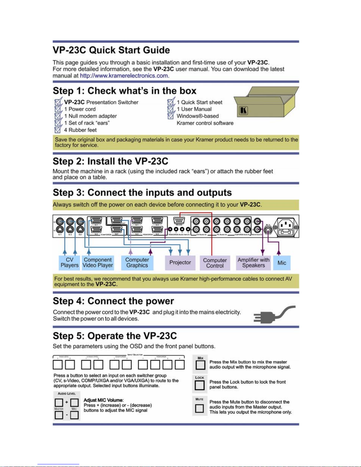
Congratulations on purchasing your Kramer VP-23C Presentation Switcher, which
is ideal for the following typical applications:
• Presentation and conference room systems
• Production studios, as well as rental and staging

2 VP-23C - Getting Started
2 Getting Started
We recommend that you:
• Unpack the equipment carefully and save the original box and packaging
materials for possible future shipment
• Review the contents of this user manual
Use Kramer high performance high resolution cables
Use only the power cord that is supplied with this machine
Go to http://www.kramerelectronics.com to check for up-to-date
user manuals, application programs, and to check if firmware
upgrades are available (where appropriate).
2.1 Achieving the Best Performance
To achieve the best performance:
• Use only good quality connection cables to avoid interference, deterioration
in signal quality due to poor matching, and elevated noise levels (often
associated with low quality cables)
• Avoid interference from neighboring electrical appliances that may adversely
influence signal quality
• Position your Kramer VP-23C away from moisture, excessive sunlight and
dust
i

VP-23C - Overview 3
3 Overview
The VP-23C is a high-quality presentation switcher designed for a wide variety of
presentation and multimedia applications. The VP-23C includes four switcher
groups, that combine the functions of a 2x1 switcher for composite video, a 2x1
switcher for s-Video, a 2x1 switcher for component video/UXGA, and a 4x1
switcher for VGA/UXGA type signals. Each video input has its own unbalanced
stereo audio input. There is also an independent unbalanced stereo master audio
output, which can select a signal from any of the 10 audio inputs.
In addition the VP-23C features:
• 10 selector buttons, and front panel control buttons for the master audio
output level and microphone level
• Control of each switcher group independently from the other sections
• HDTV compatibility
• Control via the front panel buttons or by RS-232 serial commands
transmitted by a touch screen system, PC, or other serial controller
• Mixing the mic with the master output signal or by muting the master output
signal
• A lock button to prevent unintentional tampering with the front panel buttons
3.1 Defining the VP-23C Presentation Switcher
This section defines the VP-23C.
4 VP-23C - Overview
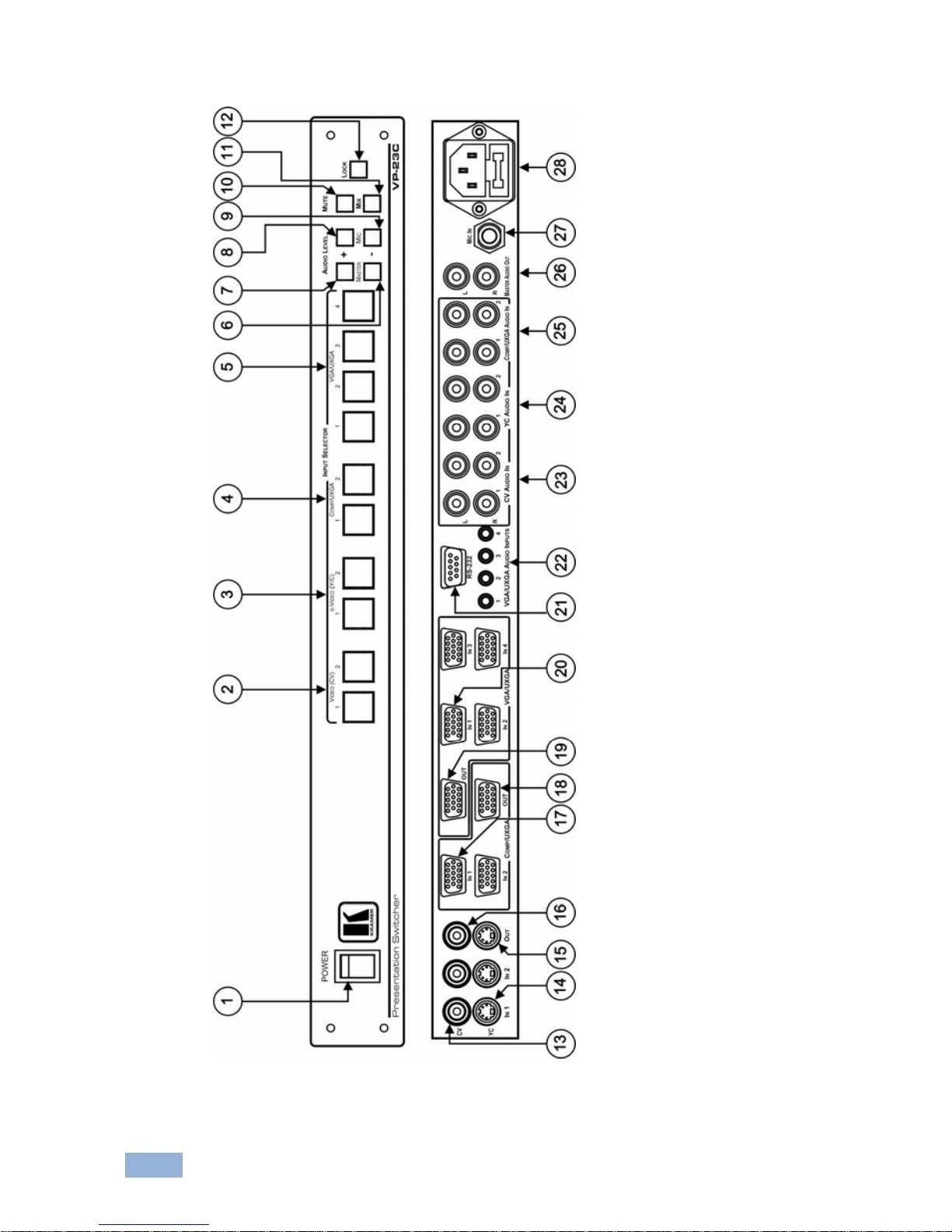
Figure 1: VP-23C Presentation Switcher
VP-23C - Overview 5
# Feature Function
1 POWER Switch Illuminated switch for turning the unit ON or OFF
2
INPUT
SELECTOR
VIDEO (CV) Buttons Select the composite video / audio input (1 and 2)
3 s-VIDEO (Y/C) Buttons Select the s-Video / audio input (1 and 2)
4 COMP/UXGA Buttons Select the component video / audio input (1 and 2)
Can also be used for UXGA inputs
5 VGA/UXGA Buttons Select the VGA/UXGA video / audio input (from 1 to 4)
6
AUDIO
LEVEL
MASTER
- Button Decrease the master audio signal level
7 + Button Increase the master audio signal level
8
MIC
+ Button Increase the microphone audio signal level
9 - Button Decrease the microphone audio signal level
10 MUTE Button Press to disable/enable the Master Audio output
Except for the microphone signal in the MIX mode
11 MIX Button Press to toggle. When on, mixes the microphone signal
with the Master Audio output
When the MUTE button and the MIX button are
pressed, only the microphone signal is transferred to
the output
12 LOCK Button Press and hold to lock/unlock the front panel buttons
13 CV IN RCA Connectors Connect to the composite video sources (IN 1 and IN 2)
14 YC IN 4-pin Connectors Connect to the s-Video sources (IN 1 and IN 2)
15 YC OUT 4-pin Connector Connect to the s-Video acceptor
16 CV OUT RCA Connector Connect to the composite video acceptor
17 COMP/UXGA IN 15-pin HD C onne ctor s Connect to the component video or UXGA sources (IN 1
and IN 2)
When the 15-pin HD connector is used for UXGA
signals, the syncs are on PIN 13 and PIN 14
18 COMP/UXGA OUT 15-pin HD Conn ecto r Connect to the component video or UXGA acceptor
19 VGA/UXGA OUT 15-pin HD Connector Connect to the VGA/UXGA video acceptor
20 VGA/UXGA IN 15-pin HD Connectors Connect to the VGA/UXGA video sour ces (f rom IN 1 to 4)
21 RS-232 Connect or 9-pin D-sub connector connects to PC or Remote Controller
22 VGA/UXGA AUDIO INPUTS 3.5mm Mini
Jack Connectors
Connect to the VGA/UXGA unbalanced stereo audio
sources (from 1 to 4)
23 CV AUDIO IN RCA Connectors Connect to the composite video sources (1 and 2)
24 YC AUDIO IN RCA Connectors Connect to the s-Video unbalanced stereo audio sources
(1 and 2)
25 COMP/UXGA AUDIO IN RCA Connecto rs Connec t to the com ponen t video ster eo audio so urces (1
and 2)
26 MASTER AUDIO OUT RCA Connectors Connect to the stereo audio acceptor
The input selector button last pressed transmits the
audio input signal of the selected channel to the master
audio output
27 MIC IN 6.3mm Phone Jack Connector Connects to the microphone
28 Power Connector with Fuse AC connector enabling power supply to the unit
 Loading...