

Kramer VP-214DS User Manual

K
ramer Electronics, Ltd.
USER MANUAL
Model:
VP-214DS
4 Channel Automatic XGA Switcher
im Vertrieb von
CAMBOARD Electronics
www.camboard.de
Tel. 07131 911201
Fax 07131 911203
ce-info@camboard.de
C
ontents
i
Contents
1
Introduction 1
2
Getting Started 1
3
Overview 1
4
Your VP-214DS 4 Channel Automatic XGA Switcher 2
5
Installing on a Rack 6
5.1
Before Installing on a Rack 6
5.1.1
CAUTION!! 6
5.2
Instructions for Rack-Mounting 6
6
Connecting a VP-214DS 4 Channel Automatic XGA Switcher 7
6.1
Connecting a Single Unit or Several VP-214DS Machines 7
6.2
Controlling via RS-232 (for example, using a PC) 9
6.3
Controlling via RS-485 9
6.4
Controlling via ETHERNET 10
6.4.1 Connecting the ETHERNET port via a Crossover Cable 10
6.4.2 Connecting the ETHERNET via a Straight-Through Cable 12
6.5
Setting the Dipswitches 12
6.5.1 MACH. NO. (Machine Number) Dipswitches Setup 13
6.6
Connecting Several VP-214DS Machines 14
6.7
Control Configuration via the Ethernet Port 15
6.8
Resetting the Unit 15
7
Operating the VP-214DS 16
7.1
Selecting the Master Source Signal 16
7.2
Connecting the REMOTE Connector 18
8
Firmware Upgrading 19
8.1
Downloading from the Internet 19
8.2
Connecting the PC to the RS-232 Port 19
8.3
Upgrading Firmware 19
9
Technical Specifications 24
10
Table of Hex Codes for Serial Communication 24
10.1 Hex Codes for Assigning the Master Status 24
10.2 Hex Codes for Request Status of a video Output 25
10.3 Hex Codes for Request whether a Valid Input is Detected 25
10.4 Hex Codes for Lock Front Panel 25
11
Kramer Protocol 2000 26
im Vertrieb von
CAMBOARD Electronics
www.camboard.de
Tel. 07131 911201
Fax 07131 911203
ce-info@camboard.de

KRAMER: SIMPLE CREATIVE TECHNOLOGY
Contents
ii
Figures
Figure 1: VP-214DS 4 Channel Automatic XGA Switcher 3
Figure 2: VP-214DS Underside Panel 5
Figure 3: Connecting the VP-214DS 8
Figure 4: Connecting a PC without using a Null-modem Adapter 9
Figure 5: RJ-45 PINOUT 10
Figure 6: Local Area Connection Properties Window 11
Figure 7: Internet Protocol (TCP/IP) Properties Window 11
Figure 8: VP-214DS Dipswitches 12
Figure 9: Connecting Several VP-214DS Machines 15
Figure 10: Remote Terminal Block Connector 18
Figure 11: Splash Screen 20
Figure 12: Atmel – Flip Window 20
Figure 13: Device Selection Window 20
Figure 14: Selecting the Device from the Selection Window 21
Figure 15: Loading the Hex 21
Figure 16: RS-232 Window 22
Figure 17: Atmel – Flip Window (Connected) 22
Figure 18: Atmel – Flip Window (Operation Completed) 23
Tables
Table 1: Front Panel VP-214DS 4 Channel Automatic XGA Switcher Features 4
Table 2: Rear Panel VP-214DS 4 Channel Automatic XGA Switcher Features 4
Table 3: VP-214DS Underside Panel Features 5
Table 4: Recommended Ambient Temperature and Humidity Range 6
Table 5: Crossover Cable RJ-45 PINOUT 10
Table 6: Straight-through Cable RJ-45 PINOUT 12
Table 7: Dipswitch Settings 12
Table 8: MACH. NO. Dipswitch Settings 13
Table 9: Input Button Indications 16
Table 10: Input Button Functionality 17
Table 11: Technical Specifications of the VP-214DS 24
Table 12: VP-214DS Hex Codes for Assign of Master Status 24
Table 13: VP-214DS Hex Codes for Request Status of a Video Output 25
Table 14: VP-214DS Hex Codes for Requesting Detection of Valid Input 25
Table 15: Protocol Definitions 26
Table 16: Instruction Codes for Protocol 2000 27
im Vertrieb von
CAMBOARD Electronics
www.camboard.de
Tel. 07131 911201
Fax 07131 911203
ce-info@camboard.de

I
ntroduction
1
1 Introduction
Welcome to Kramer Electronics (since 1981): a world of unique, creative and
affordable solutions to the infinite range of problems that confront the video,
audio and presentation professional on a daily basis. In recent years, we have
redesigned and upgraded most of our line, making the best even better! Our
350-plus different models now appear in 8 Groups
1
, which are clearly defined
by function.
Congratulations on purchasing your Kramer VP-214DS 4 Channel Automatic
XGA Switcher, which is ideal for any system requiring multi-channel
automatic computer and presentation XGA routing.
The package includes the following items:
VP-214DS 4 Channel Automatic XGA Switcher
Power cord and Null-modem adapter
Windows®-based Configuration Manager, XPort software and Com Port
Redirector
Windows®-based Kramer control software
This user manual2
2 Getting Started
We recommend that you:
Unpack the equipment carefully and save the original box and packaging
materials for possible future shipment
Review the contents of this user manual
Use Kramer high performance high resolution cables
3
3 Overview
The high performance VP-214DS 4 Channel Automatic XGA Switcher is a
high performance 2x1 4-channel automatic switcher for computer graphics
signals. The VP-214DS detects the presence of the active XGA-type input
signal, and automatically switches to the active input. If signals are present on
1 GROUP 1: Distribution Amplifiers; GROUP 2: Video and Audio Switchers, Matrix Switchers and Controllers; GROUP 3:
Video, Audio, VGA/XGA Processors; GROUP 4: Interfaces and Sync Processors; GROUP 5: Twisted Pair Interfaces;
GROUP 6: Accessories and Rack Adapters; GROUP 7: Scan Converters and Scalers; and GROUP 8: Cables and Connectors
2 Download up-to-date Kramer user manuals from our Web site at http://www.kramerelectronics.com
3 The complete list of Kramer cables is on our Web site at http://www.kramerelectronics.com
im Vertrieb von
CAMBOARD Electronics
www.camboard.de
Tel. 07131 911201
Fax 07131 911203
ce-info@camboard.de

KRAMER: SIMPLE CREATIVE TECHNOLOGY
Your VP-214DS 4 Channel Automatic XGA Switcher
2
both inputs, by default, the master source signal is selected1.
In addition, the VP-214DS:
Has a video bandwidth of 300MHz, to ensure transparent operation at the
highest resolutions
Includes 4 automatic 2x1 switchers
Features automatic input signal detection
Includes ID BIT control
2
for each channel
Includes a looping XGA input with a loop termination switch
Includes remote control contact closure
Has a PANEL LOCK button for locking the front panel to prevent
unintentional operation
Control the VP-214DS using the front panel buttons, or remotely via:
RS-485 or RS-232 serial commands transmitted by a touch screen system,
PC, or other serial controller
Ethernet
Remote control contact closure
The VP-214DS is dependable, rugged and fits into one vertical space (1U) of
a standard 19" rack.
To achieve the best performance:
Connect only good quality connection cables, thus avoiding interference,
deterioration in signal quality due to poor matching, and elevated noiselevels (often associated with low quality cables)
Avoid interference from neighboring electrical appliances and position
your Kramer VP-214DS away from moisture, excessive sunlight and dust
4 Your VP-214DS 4 Channel Automatic XGA Switcher
Figure 1 illustrates the front and rear panels of the VP-214DS. Table 1 and
Table 2 define the front and rear panels of the VP-214DS, respectively.
1 You can select the master source signal via front panel buttons (IN 1 or IN 2 for each channel), or remotely via PC
2 Sometimes notebook computers refuse to output a XGA signal to an external XGA monitor. By setting the ID BIT to ON,
the notebook will output to an external XGA monitor
im Vertrieb von
CAMBOARD Electronics
www.camboard.de
Tel. 07131 911201
Fax 07131 911203
ce-info@camboard.de

Your VP-214DS 4 Channel Automatic XGA Switcher
3
Figure 1: VP-214DS 4 Channel Automatic XGA Switcher
im Vertrieb von
CAMBOARD Electronics
www.camboard.de
Tel. 07131 911201
Fax 07131 911203
ce-info@camboard.de
KRAMER: SIMPLE CREATIVE TECHNOLOGY
Your VP-214DS 4 Channel Automatic XGA Switcher
4
Table 1: Front Panel VP-214DS 4 Channel Automatic XGA Switcher Features
# Feature Function
1
POWER Switch Illuminated switch supplying power to the unit
2 IN 1 Button Press to select input 1 as the Master Source signal (see section 7.1):
The red LED illuminates when IN 1 is the Master Source and the signal
on the input is inactive
The blue LED illuminates when IN 1 is not the Master Source and the
signal on the input is active
Both the blue and red LEDs illuminate (creating purple) when IN 1 is the
Master Source and the signal on the input is active
Button is not illuminated when IN 1 is not the Master Signal and the
signal is inactive
3
MANUAL SELECTOR
CHANNEL A
1
IN 2 Button Press to select input 2 as the Master Source signal (see section 7.1):
The red LED illuminates when IN 2 is the Master Source and the signal
on the input is inactive
The blue LED illuminates when IN 2 is not the Master Source and the
signal on the input is active
Both the blue and red LEDs illuminate (creating purple) when IN 2 is the
Master Source and the signal on the input is active
Button is not illuminated when IN 2 is not the Master Signal and the
signal is inactive
4 PANEL LOCK Button Press to lock/unlock the front panel to prevent unintentional operation
T
able 2: Rear Panel VP-214DS 4 Channel Automatic XGA Switcher Features
#
F
eature
F
unction
5 HD15F IN 1 Connector Connects to the IN 1 XGA source
6
HD15F IN 2 Connector Connects to the IN 2 XGA source
7
HD15F LOOP Connector Connects to a monitor looped to IN1
8 TERM Button
Release to terminate IN 1 with 75 when connecting a monitor
to the LOOP connector
9
CHANNEL A
1
HD15F OUT Connector Connects to the output XGA acceptor
10 ETHERNET Connector Connects to the PC or other controller through computer
networking
1
1 PROG Button Push in to program for upgrading to the latest Kramer firmware
(see section 8.2), or release for Normal (the factory default)
1
2 RS-485 Connector Use for bi-directional communication with another unit
13 Setup Dipswitches Set for machine setup (see section 6.5)
1
4 REMOTE Terminal Block Connects to a dry contact switch (see section 7.2)
15 RS-232 DB 9F Connector Connects to the PC or other Serial Controller
1
6 Power Connector with Fuse AC connector enabling power supply to the unit
1 For each of the four channels: A, B, C and D
im Vertrieb von
CAMBOARD Electronics
www.camboard.de
Tel. 07131 911201
Fax 07131 911203
ce-info@camboard.de
Y
our VP-214DS 4 Channel Automatic XGA Switcher
5
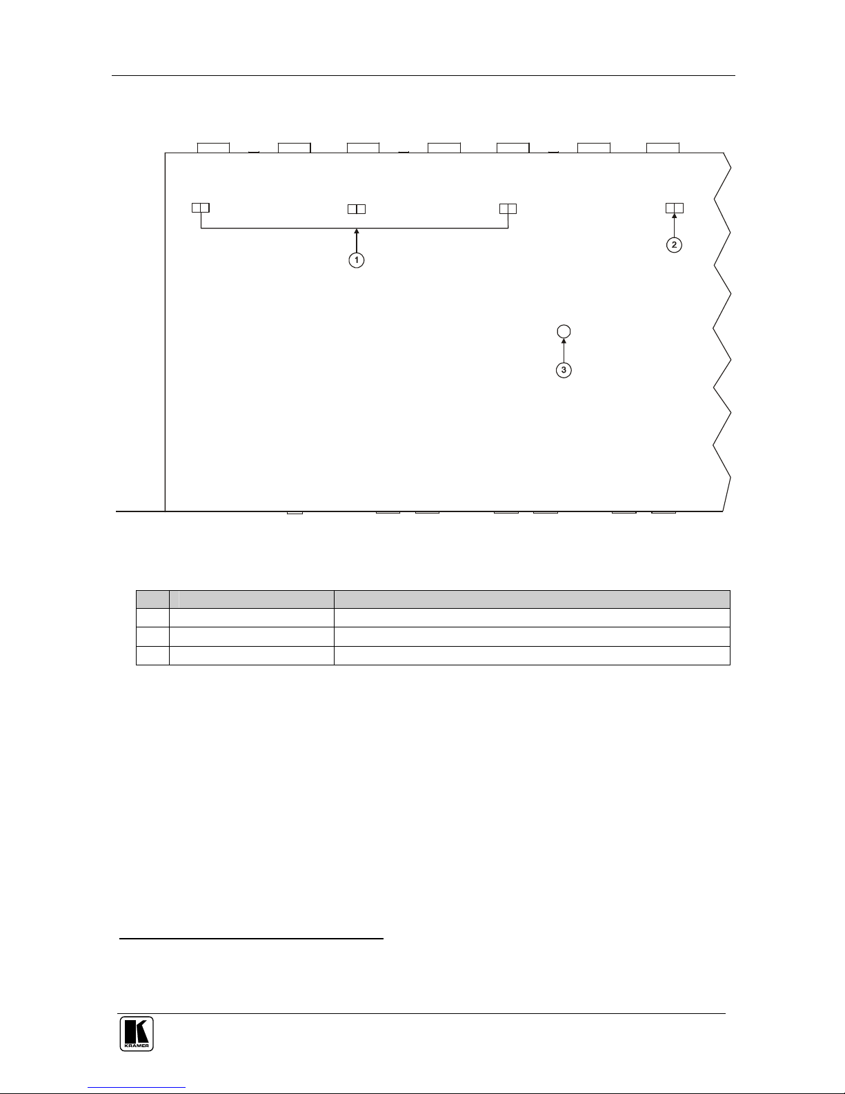
Figure 2 illustrates the relevant underside of the VP-214DS unit and Table 3
defines the underside features.
O
N
ID BIT
PROG
RESET
O
N
ID BIT
ON
ID BIT
ON
I
D BIT
Figure 2: VP-214DS Underside Panel
Table 3: VP-214DS Underside Panel Features
#
F
eature
F
unction
1
ID BIT Switches1 Slide switch to the left to set to ON2; and to the right to set to OFF
2 ID BIT Switch3 Slide switch to the right to set to ON2 and to the left to set to OFF
3
PROG RESET Press to reset the unit prior to a firmware upgrade (see section 6.8)
1 For channels: A, B and C
2 Enabling the notebook to output an XGA signal to an external XGA monitor
3 For channel D
im Vertrieb von
CAMBOARD Electronics
www.camboard.de
Tel. 07131 911201
Fax 07131 911203
ce-info@camboard.de
KRAMER: SIMPLE CREATIVE TECHNOLOGY
Installing on a Rack
6
5 Installing on a Rack
This section describes what to do before installing on a rack (see section 5.1)
and how to install on a rack (see section 5.2).
5.1 Before Installing on a Rack
Before installing the machine in a 19" rack, be sure that the environment is
within the recommended range:
Table 4: Recommended Ambient Temperature and Humidity Range
Operating temperature range +5 to +45 Deg. Centigrade
Operating humidity range 5 to 65 % RHL, non-condensing
S
torage temperature range -20 to +70 Deg. Centigrade
S
torage humidity range 5 to 95% RHL, non-condensing
5.1.1 CAUTION!!
When installing the VP-214DS in a 19" rack, avoid hazards by taking care that:
1. It is located within the recommended environmental conditions, as the
operating ambient temperature of a closed or multi-unit rack assembly
may exceed the room ambient temperature.
2. Once rack-mounted, enough air will still flow around the machine.
3. The machine is placed straight in the correct horizontal position.
4. You do not overload the circuit(s). When connecting the machine to the
supply circuit, overloading the circuits might have a detrimental effect
on overcurrent protection and supply wiring. Refer to the appropriate
nameplate ratings for information. For example, for fuse replacement,
see the value printed on the product label.
5. The machine is earthed (grounded) in a reliable way and is connected
only to an electricity socket with grounding. Pay particular attention to
supply connections other than direct connections to the branch circuit
(for example, the use of power strips), and that you use only the power
cord that is supplied with the machine.
5.2 Instructions for Rack-Mounting
To install the VP-214DS in a 19" rack, place the rack ears of the machine
against the rack rails of the rack, and insert the proper rack screws through
each of the four holes in the rack ears
1
.
1 Always mount the machine in the rack before you attach any cables or connect the machine to the power. If you are using a
Kramer rack adapter kit (for a machine that is not 19"), refer to the Rack Adapters user manual (download it at:
http://www.kramerelectronics.com) for installation instructions
im Vertrieb von
CAMBOARD Electronics
www.camboard.de
Tel. 07131 911201
Fax 07131 911203
ce-info@camboard.de

C
onnecting a VP-214DS 4 Channel Automatic XGA Switcher
7
6 Connecting a VP-214DS 4 Channel Automatic XGA Switcher
This section describes how to:
Connect the VP-214DS unit (see section 6.1)
Connect the VP-214DS for control via RS-232 (see section 6.2), RS-485 (see
section 6.3) and/or the Ethernet (see sections 6.4 and 6.7)
Connect several VP-214DS machines (see section 6.6)
Set the dipswitches (see section 6.5)
Reset the unit (see section 6.8)
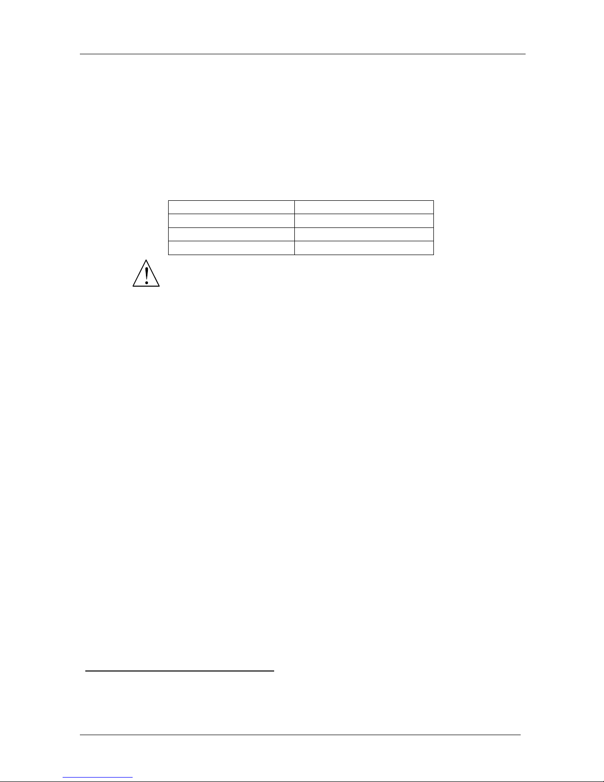
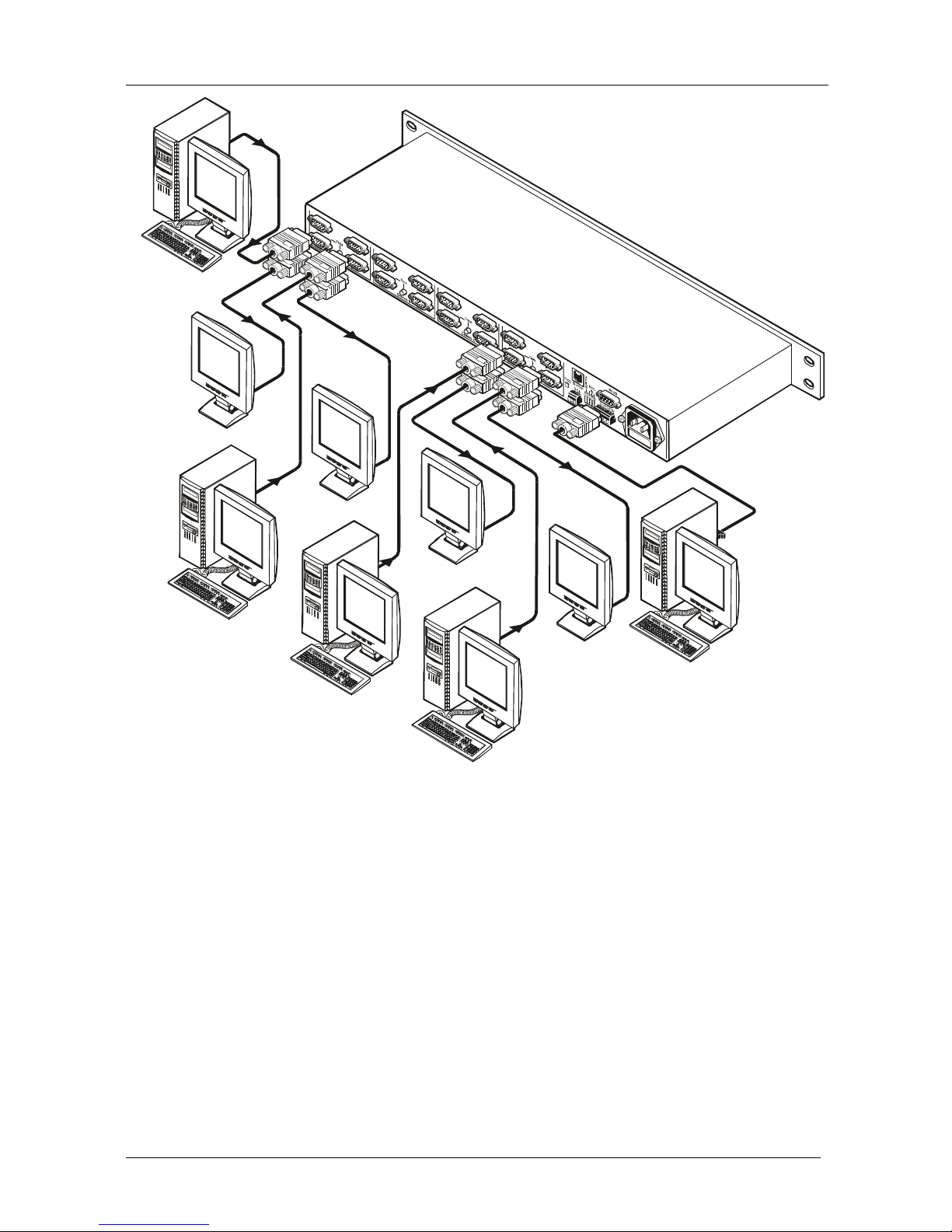
6.1 Connecting a Single Unit or Several VP-214DS Machines
To connect the VP-214DS 4 Channel Automatic XGA Switcher, connect the
following to the rear panel (see Figure 3):
1. For each channel
1
(A, B, C and D):
Connect XGA sources to the IN 1 and IN 2 connectors (for example
a computer or a laptop)
Connect the OUT connector to a computer graphics acceptor (for
example, a monitor or a projector)
Connect an additional monitor to the LOOP connector if required
2
2. Connect the power cord
3
(not shown in Figure 3)
3. Connect to a controlling device (optional – see sections 6.2, 6.3 and 6.4).
4. Connect the RS-485 port to additional units (optional – section 6.6).
5. Set the dipswitches (see section 6.5).
1 You do not have to connect the inputs on all channels
2 When connecting an additional monitor, press the channel’s TERM button
3 We recommend that you use only the power cord that is supplied with this machine
im Vertrieb von
CAMBOARD Electronics
www.camboard.de
Tel. 07131 911201
Fax 07131 911203
ce-info@camboard.de
KRAMER: SIMPLE CREATIVE TECHNOLOGY
Connecting a VP-214DS 4 Channel Automatic XGA Switcher
8
Display D
RS-232
L
ocal
D
isplay D
Computer
G
raphics Source D2
Computer
G
raphics Source D1
D
isplay A
Local
Display A
C
omputer
Graphics Source A2
Computer Graphics
Source A1
Figure 3: Connecting the VP-214DS
im Vertrieb von
CAMBOARD Electronics
www.camboard.de
Tel. 07131 911201
Fax 07131 911203
ce-info@camboard.de
 Loading...