

Page 1

Kramer Electronics, Ltd.
USER MANUAL
Model:
VP-111K
UXGA Line Driver
Page 2

Contents
Contents
1
Introduction 1
2
Getting Started 1
2.1 Quick Start 2
3
Overview 3
4
Your VP-111K UXGA Line Driver 4
5
Connecting the VP-111K UXGA Line Driver 5
6
Technical Specifications 7
Figures
Figure 1: VP-111K UXGA Line Driver Functions 4
Figure 2: Connecting the VP-111K UXGA Line Driver 6
Tables
Table 1: VP-111K UXGA Line Driver Functions 4
Table 2: VP-111K Technical Specifications 7
i
Page 3

Introduction
1 Introduction
Welcome to Kramer Electronics! Since 1981, Kramer Electronics has been
providing a world of unique, creative, and affordable solutions to the vast
range of problems that confront the video, audio, presentation, and
broadcasting professional on a daily basis. In recent years, we have
redesigned and upgraded most of our line, making the best even better! Our
1,000-plus different models now appear in 11 groups1 that are clearly
defined by function.
Thank you for purchasing the Kramer TOOLS VP-111K UXGA Line
Driver, which is ideal for:
Dual monitor systems (local and remote)
Presentation systems: for remote transmission and cable
equalization
Each package includes the following items:
The VP-111K UXGA Line Driver
Power adapter (5V DC Input)
This user manual2
2 Getting Started
We recommend that you:
Unpack the equipment carefully and save the original box and
packaging materials for possible future shipment
Review the contents of this user manual
Use Kramer high-performance high-resolution cables3
1 GROUP 1: Distribution Amplifiers; GROUP 2: Switchers and Matrix Switchers; GROUP 3: Control Systems; GROUP 4:
Format/Standards Converters; GROUP 5: Range Extenders and Repeaters; GROUP 6: Specialty AV Products; GROUP 7:
Scan Converters and Scalers; GROUP 8: Cables and Connectors; GROUP 9: Room Connectivity; GROUP 10: Accessories
and Rack Adapters; GROUP 11: Sierra Products
2 Download up-to-date Kramer user manuals from our Web site at http://www.kramerelectronics.com
3 The complete list of Kramer cables is on our Web site at http://www.kramerelectronics.com
1
Page 4

Getting Started
2.1 Quick Start
This quick start chart summarizes the basic setup and operation steps.
2
KRAMER: SIMPLE CREATIVE TECHNOLOGY
Page 5

Overview
3 Overview
The high-performance Kramer VP-111K is a line driver for signals
exceeding UXGA. It accepts one input, provides correct buffering and
isolation, and outputs the amplified and equalized signal to a remote
acceptor. It also loops the input signal to a local monitor (or some other
acceptor).
The VP-111K features:
High bandwidth (500MHz) that drives very long high-resolution
lines1 ensuring transparency even at highest resolution
A TERM switch for input signal termination
KR-ISP™ Advanced Sync Processing that ensures compatibility
with a wide range of computers (even if the sync level is too low)
by restoring the sync signal waveform
To achieve the best performance:
Use only good quality connection cables2 to avoid interference,
deterioration in signal quality due to poor matching, and elevated
noise levels (often associated with low quality cables).
Avoid interference from neighboring electrical appliances that
may adversely influence signal quality and position your Kramer
VP-111K away from moisture, excessive sunlight and dust
Caution – No operator-serviceable parts inside unit.
Warning – Use only the Kramer Electronics input power
wall adapter that is provided with this unit3.
Warning – Disconnect power and unplug unit from wall
before installing or removing device or servicing unit.
1 Up to 100 meters (300ft) when using good quality cable
2 Available from Kramer Electronics on our Web site at http://www.kramerelectronics.com
3 For example, part number 2535-052002
3
Page 6

Your VP-111K UXGA Line Driver
4 Your VP-111K UXGA Line Driver
Figure 1 and Table 1 define the unit.
Figure 1: VP-111K UXGA Line Driver Functions
Table 1: VP-111K UXGA Line Driver Functions
# Feature Function
1 EQ. Trimmer Adjusts1 the cable compensation equalization level for the output
2 OUTPUT 15-pin HD Connector Connect to the computer graphics acceptor
3 5V DC Connector +5V DC for powering the unit
4 INPUT 15-pin HD Connector Connect to the computer graphics source
5 LOOP 15-pin HD Connector Connect to an additional graphics acceptor
6 TERM Pushbutton Switch Press IN to 75 (when a local monitor is not used); press OUT to
7 ON LED Illuminates green when receiving power
Hi-Z (when a local monitor is connected to the LOOP connector)
1 Insert a screwdriver into the hole and carefully rotate it, to trim the level
4
KRAMER: SIMPLE CREATIVE TECHNOLOGY
Page 7

Connecting the VP-111K UXGA Line Driver
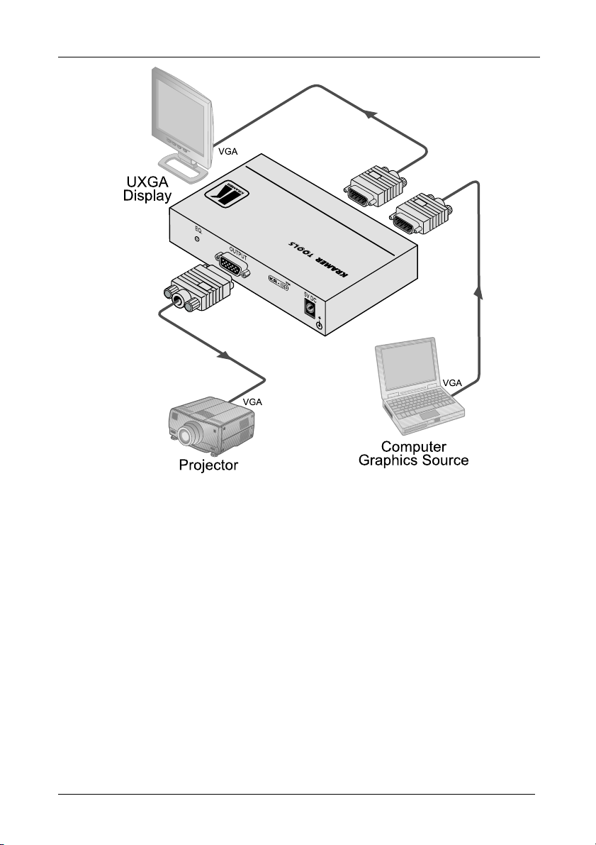
5 Connecting the VP-111K UXGA Line Driver
To connect the VP-111K, as the example in Figure 2 illustrates, do the
following1:
1. Connect a computer graphics source (for example, a laptop) to the INPUT
15-pin HD (F) connector.
2. Connect the OUTPUT 15-pin HD (F) connector to an acceptor (for
example, a projector).
3. Connect the LOOP 15-pin HD (F) connector to an acceptor (for
example, a local display).
4. Connect the 5V DC power adapter to the 5V DC socket and connect the
transformer to the mains electricity (not illustrated in Figure 2).
5. Set the termination switch as follows:
If no acceptor is attached to the LOOP connector, press the
pushbutton in to the 75 setting
If a acceptor is attached to the LOOP connector, set the
pushbutton out to HI-Z setting
1 Switch OFF the power on each device before connecting it to your VP-111K. After connecting your VP-1 11K, switch on
its power and then switch on the power on each device
5
Page 8
Connecting the VP-111K UXGA Line Driver
Figure 2: Connecting the VP-111K UXGA Line Driver
6
KRAMER: SIMPLE CREATIVE TECHNOLOGY
Page 9

Technical Specifications
6 Technical Specifications
The VP-111K technical specifications are shown in Table 2:
Table 2: VP-111K Technical Specifications1
INPUT: 1 XGA input on a 15-pin HD connector
OUTPUTS: 1 XGA output and loop on 15-pin HD connectors
MAX OUTPUT LEVEL: 2.2Vpp
BANDWIDTH (-3dB): 500MHz
DIFF. GAIN: 0.05%
DIFF. PHASE: 0.05Deg
K-FACTOR: <0.05%
S/N RATIO: 75dB
CONTROLS: 0 to 10dB, equalization @50MHz
COUPLING: DC
POWER SOURCE: 5V DC, 114mA
DIMENSIONS 12cm x 7.2cm x 2.4cm (4.7" x 2.8" x 1.0") W, D, H
WEIGHT: 0.3kg (0.7lbs)
ACCESSORIES: 5V DC power supply
OPTIONS: 19” rack mount
1 Specifications are subject to change without notice
7
Page 10

8
Page 11

For the latest information on our products and a list of Kramer
distributors, visit our Web site: www.kramerelectronics.com
where updates to this user manual may be found.
We welcome your questions, comments and feedback.
Safety Warning:
Disconnect the unit from the power supply before
opening/servicing.
Caution
PN:
2900- 000488
Rev:
1
Kramer Electronics, Ltd.
Web site: www.kramerelectronics.com
E-mail: info@kramerel.com
P/N: 2900-000488 REV 1
 Loading...