

Page 1

Kramer Electronics, Ltd.
Preliminary
USER MANUAL
Models:
VM-2N, Video Audio Distributor
VM-5S, Video Audio Distributor
VM-50HN, Headphone Distributor
VM-50V, 1:5 Video Distributor
VM-50YC, 1:5 s-Video Distributor
Page 2

Contents
i
Contents
1 Introduction 1
2 Getting Started 1
2.1 Quick Start 2
3 Overview 4
3.1 The VM-2N Video Audio Distributor 4
3.2 The VM-5S Video Audio Distributor 4
3.3 The VM-50HN Headphone Distributor 5
3.4 The VM-50V 1:5 Video Distributor 5
3.5 The VM-50YC 1:5 s-Video Distributor 5
4 Your Distributor 6
4.1 Your VM-2N Video Audio Distributor 7
4.2 Your VM-5S Video Audio Distributor 8
4.3 Your VM-50HN Headphone Distributor 9
4.4 Your VM-50V 1:5 Video Distributor 10
4.5 Your VM-50YC 1:5 s-Video Distributor 11
5 Connecting the Distributors 11
5.1 Connecting the VM-2N Video Audio Distributor 12
5.2 Connecting the VM-5S Video Audio Distributor 13
5.3 Connecting the VM-50HN Headphone Distributor 14
5.4 Connecting the VM-50V 1:5 Video Distributor 15
5.5 Connecting the VM-50YC 1:5 s-Video Distributor 16
6 Technical Specifications 17
Figures
Figure 1: VM-2N Video Audio Distributor 7
Figure 2: VM-5S Video Audio Distributor
8
Figure 3: VM-50HN Headph one D is t ri butor
9
Figure 4: VM-50V 1:5 Video Distributor 10
Figure 5: VM-50YC 1:5 s-Video Distributor
11
Figure 6: Connecting the VM-2N Video Audio Distributor
12
Figure 7: Connecting the VM-5S Video Audio Distributor
13
Figure 8: Connecting the VM-50HN Headphone Distributor 14
Figure 9: Connecting the VM-5 0 V 1:5 Video Distri b ut or
15
Figure 10: Connecting the VM-50YC 1:5 s-Video Distributor
16
Page 3

KRAMER: SIMPLE CREATIVE TECHNOLOGY
Contents
ii
Tables
Table 1: VM-2N Video Audio Distributor 7
Table 2: VM-5S Video Audio Distributor 8
Table 3: VM-50HN Headphone Dis t ri butor
9
Table 4: VM-50V 1:5 Video Distributor
10
Table 5: VM-50YC 1:5 s-Vide o D is t ri butor
11
Table 6: VM-2N Technical Specification s 17
Table 7: VM-50HN Technical Specifications
17
Table 8: VM-5S Techn ical Specifications
18
Table 9: VM-50V Technical Specifications
18
Table 10: VM-50YC Technical Specifications 19
Page 4

Introduction
1
1
1 Introduction
Welcome to Kramer Electronics! Since 1981, Kramer Electronics has been
providing a world of unique, creative, and affordable solutions to the vast
range of problems that confront the video, audio, presentation, and
broadcasting professional on a daily basis. In recent years, we have
redesigned and upgraded most of our line, making the best even better! Our
1,000-plus different models now appear in 11 groups
1
Thank yo u for purchasing the Kra mer VM-2N, VM-5S, VM-50HN,
VM-50V, VM-50YC Video Distribution Amplifiers, which are ideal for:
that are clearly
defined by function.
• Any professional A/V system requi ring a compact, high-quality DA
• Retail stores and other point-of-sale display systems
• Security and CCTV applications
• Studio RGB/YUV distribution
Each package includes the following items:
• The VM-2N, VM-5S, VM-50HN, VM-50V or VM-50YC
• Power cord
2
• This user manual
or power adapter (12V DC input)
3
2 Getting Started
We recommend that you:
• Unpack t he equip ment carefully and s ave the original box and
packaging materials for possible future shipment
• Review the contents of this user manual
• Use Kramer high-performance high-resolution cables
4
1 GROUP 1: Distribution Amplifiers; GROUP 2: Switchers and Matrix Switchers; GROUP 3: Control Systems;
GROUP 4: Format/Standards Converters; GROUP 5: Range Extenders and Repeaters; GR OUP 6: Specialty AV Products;
GROUP 7: Scan Converters and Scalers; GROUP 8: Cables and Connectors; GROUP 9: Room Connectivity;
GROUP 10: Accessories and Rack Adapters; GROUP 11: Sierra Products
2 We recommend that you use only the power cord supplied with this device
3 Download up-to-date Kramer user manuals from our Web site at
http://www.kramerelectronics.com
4 The complete list of Kramer cables is on our Web site at
http://www.kramerelectronics.com
Page 5

KRAMER: SIMPLE CREATIVE TECHNOLOGY
Getting Started
2
2.1 Quick Start
This quick start chart summarizes the basic setup and operation steps.
Page 6

Getting Started
3
3
Page 7

KRAMER: SIMPLE CREATIVE TECHNOLOGY
Overview
4
3 Overview
This sect ion gives an overview of the:
• VM-2N Video Audio Distr i butor , see section
3.1
• VM-5S Video Audio Distributor, see section
3.2
• VM-50HN Headphone Distributor, see section
3.3
• VM-50V 1:5 Video Distributor, see section
3.4
• VM-50YC 1:5 s-Video Distributor, see section
3.5
3.1 The VM-2N Video Audio Distributor
The Kramer VM-2N is a high-performance distribution a mplifier for
composite or SDI video and unbalanced stereo audio signals. It takes one
input, provides correct buffering and isolation and distributes the signal to
two identical outputs.
More specifically, the VM-2N features:
• High bandwidth (Y) of 400MHz (-3dB)
• 1 composite video input and 2 outputs on BNC connectors
• 1 unbalanced stereo input and 2 outputs on RCA connectors
• Level and equalization controls
• AC power supply
• Compact desktop size
3.2 The VM-5S Video Audio Distributor
The Kramer VM-5S is a high-performance distribution amplifier for
composite or SDI video and unbalanced stereo audio signals. It takes
one input, provides correct buffering and isolation and distributes
the signal to 5 identical outputs.
More specifically, the VM-5S features:
• High bandwidth of 340MHz (-3dB)
• 1 video input and 5 outputs on BNC connectors
• 1 unbalanced stereo input and 5 outputs on RCA connectors
• Looped input capability
• Selectable input signal ter mination
• Audio level, video level and equalization controls
• AC power supply
• Compact desktop size
Page 8

Overview
5
5
3.3 The VM-50HN Headphone Distributor
The Kramer MultiTOOLS
®
VM-50HN is a high-performance distribution
amplifier for headphone signals. It takes one stereo headphone input and
distributes the signal to five identical stereo head phone outputs.
More specifically, the VM-50HN features:
• 1 mono/stereo audio input and 5 outputs on 6.5mm phone connectors
with mono/stereo selector
• Level gain controls for each output
• Power LED indicator
• 12V DC power supply
• MultiTOOLS
®
size
3.4 The VM-50V 1:5 Video Distributor
The Kramer VM-50V is a high-performance distrib ution amplifier for
composite or SD I signals. It takes one input, provides correct buffering and
isolation, and distributes the signal to five identical outputs.
More specifically, the VM-50V features:
• High bandwidth of 480MHz (-3dB)
• 1 video input, 1 looping input, and 5 outputs on BNC connectors
• Selectable input signal ter mination
• Signal level and equalization controls
• 12V DC power supply
• Compact desktop size
3.5 The VM-50YC 1:5 s-Video Distributor
The Kramer VM-50YC is a high-performance distribution amplifier for
s-Video (Y/C) signals. It takes one input, provides correct buffering and
isolation, and distributes the signal to 5 identical outputs.
More specifically, the VM-50YC features:
• High bandwidth (Y) of 285MHz (-3dB)
• 1 looping input, and 5 outputs on 4-pin connectors
• Selectable input signal ter mination
• 12V DC power supply
• Compact desktop size
Page 9

KRAMER: SIMPLE CREATIVE TECHNOLOGY
Your Distributor
6
Caution – No operator-serviceable parts inside unit.
Warning – Use only the Kra mer Electronics inpu t power
wall adapter that is provide d with this unit
1
.
Warning – Di sconnect po wer and unplug unit from wall
before i ns talling or removing device or ser vicing unit.
To achieve the best performance:
• Use only good quality connection cables
2
• Avoid interference from neighboring electrical appliances that
may adversely influence signal quality and position your Kramer
product away from moisture, excessive sunlight and dust
to avoid interference,
deterioration in signal q uality due to poor matching, and elevated
noise levels (often associa te d with low quality cables).
4 Your Distributor
This section describes the:
• VM-2N Video Audio Distr i butor , see section
4.1
• VM-5S Video Audio Distributor, see section
4.2
• VM-50HN Headphone Distributor, see section
4.3
• VM-50V 1:5 Video Distributor, see section
4.4
• VM-50YC 1:5 s-Video Distributor, see section
4.5
1 For example, part number 22535-000251
2 Available from Kramer Electronics on our Web site at http://www.kramerelectronics.com
Page 10
Your Distributor
7
7
4.1 Your VM-2N Video Audio Distributor
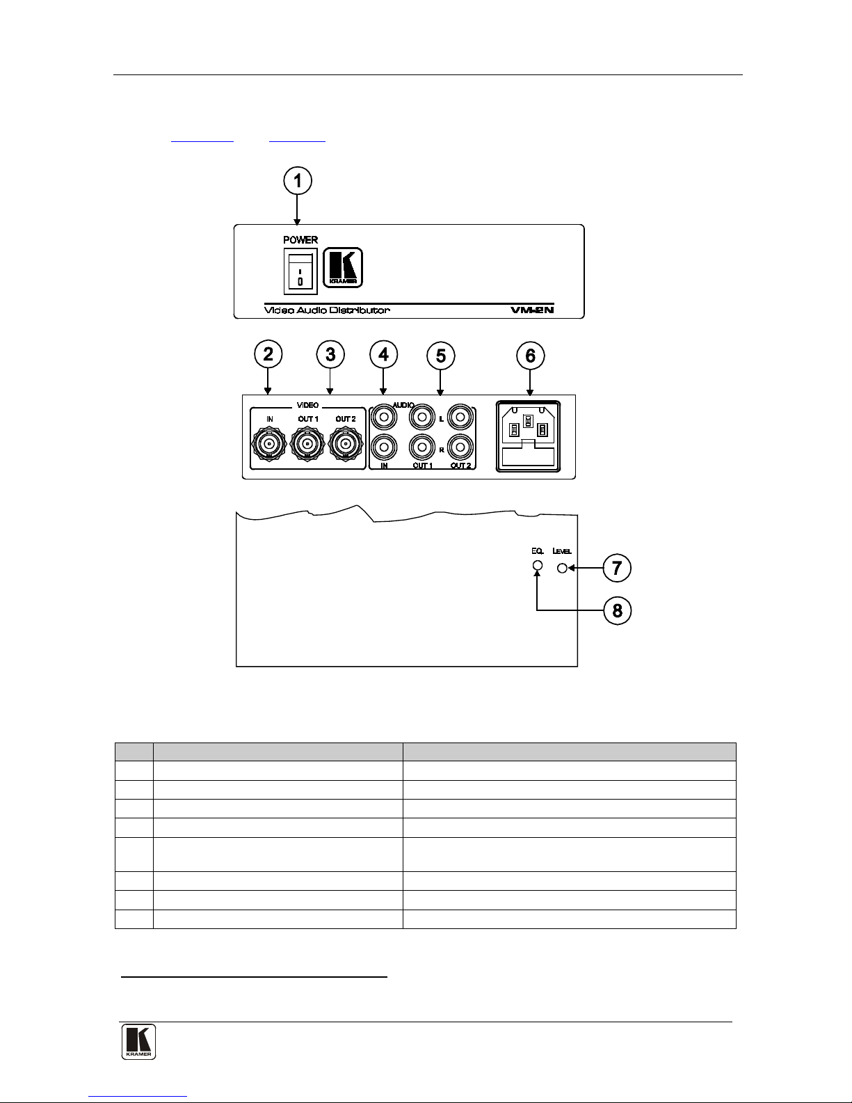
Figure 1 and Table 1 define the VM-2N.
Figure 1: VM-2N Video Audio Distributor
Table 1: VM-2N Video Audio Distributor
#
Feature
Function
1 Illuminated Power Switch Illuminated switch for turning the unit ON or OFF
2 VIDEO IN BNC Connector Connects to the video source
3 VIDEO OUT BNC Connectors Connect to the video acceptor (from 1 to 2)
4 AUDIO IN RCA Connectors (L and R) Connect to the L and R channels of the audio source
5 AUDIO OUT RCA Connectors (L and R) Connect to the L and R channels of the audi o acce pt o r
(from 1 to 2)
6 Power Connecto r wit h Fus e AC connector for supplying power to the unit
7 LEVEL Control (underside) Adjust
1
8
the audio signal output level
EQ. Control (underside) Adjust the cable compensation equalization level
1 Insert a small screwdriver into the hole and carefully rotate it to trim the level
Page 11
KRAMER: SIMPLE CREATIVE TECHNOLOGY
Your Distributor
8
4.2 Your VM-5S Video Audio Distributor
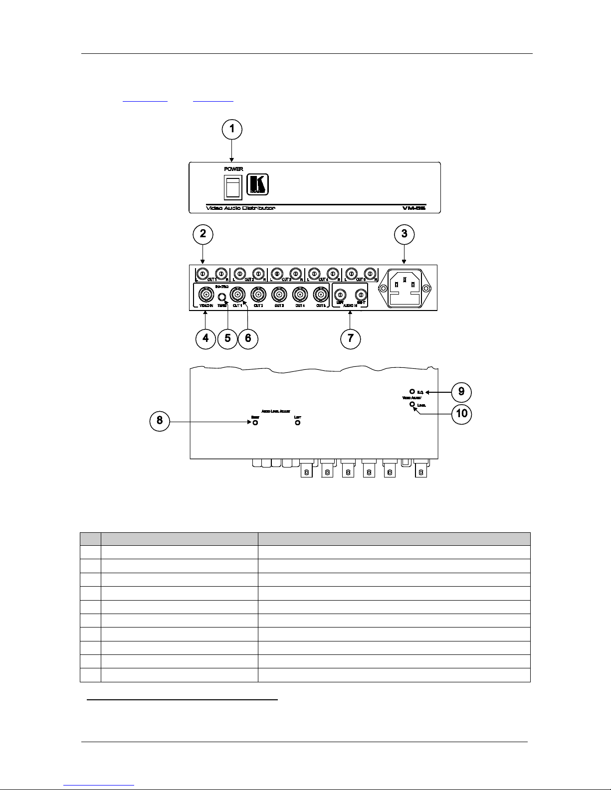
Figure 2 and Table 2 define the VM-5S.
Figure 2: VM-5S Video Audio Distributor
Table 2: VM-5S Video Au dio Distributor
#
Feature
Function
1 Illuminated Power Switch Illuminated switch for turning the unit ON or OFF
2 AUDIO OUT RCA Connectors Connect to the audio acceptor (from 1 to 5)
3 Power Connecto r wit h FUSE AC connector for supplying power to the unit
4 VIDEO IN BNC Connector Connects to the video source
5 TERM Pushbutton Switch Press IN for 75Ω input termination, leave OUT for no termin ation
6 VIDEO OUT BNC Connectors Conn ect to the video acceptors (from 1 to 5)
7 AUDIO IN RCA Connectors (L and R) Connect to the L and R channels of the audio source
8 AUDIO LEVEL ADJUST L and R Adjust
1
9
the audio signal output level
VIDEO EQ. Control (underside) Adjust1 the cable compensation equalization level
10 VIDEO LEVEL Control (underside) Adjust1 the video signal output level
1 Insert a small screwdriver into the hole and carefully rotate it to trim the level
Page 12
Your Distributor
9
9
4.3 Your VM-50HN Headphone Distributor
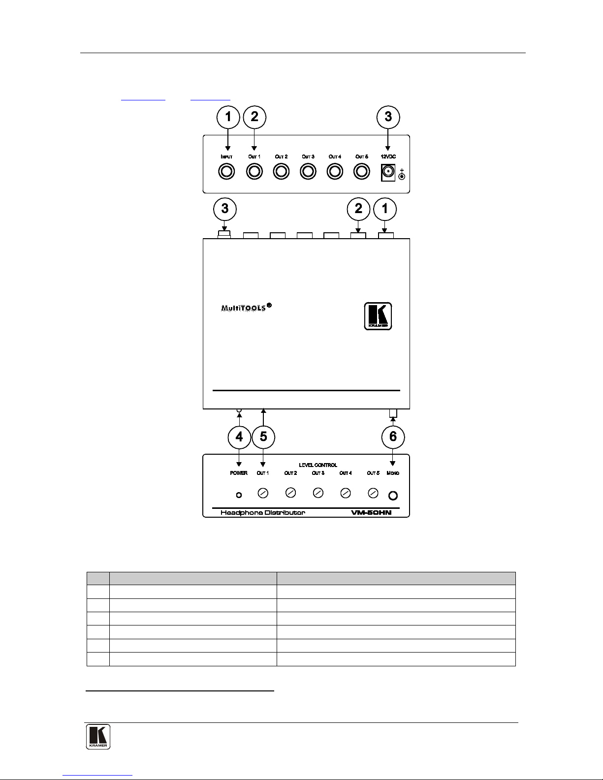
Figure 3 and Table 3 define the VM-50HN.
Figure 3: VM-50HN Headph one D is t r ibutor
Table 3: VM-50HN Headphone Distributor
#
Feature
Function
1 INPUT 6.5mm phone connector Connects to the input source
2 OUT 6.5mm phone connectors Connect to the headphones (1 to 5)
3 12V DC Connector Connects to the 12V DC power supply
4 POWER LED Illuminat es when th e un i t is ON
5 LEVEL CONTROL Potentiometers Adjust
1
6
the audio signal output level (OUT 1 to OUT 5)
MONO Pushbutton Press IN for mono audio, leave OUT for stereo audio
1 Rotate to adjust the appropriate level
Page 13
KRAMER: SIMPLE CREATIVE TECHNOLOGY
Your Distributor
10
4.4 Your VM-50V 1:5 Video Distributor
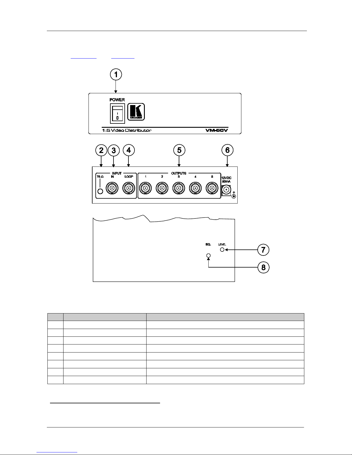
Figure 4 and Table 4 define the VM-50V.
Figure 4: VM-50V 1:5 Video Distributor
Table 4: VM-50V 1:5 Video Distributor
#
Feature
Function
1 Illuminated Power Switch Illuminated switch for turning the unit ON or OFF
2 TERM Pushbutton Switch Press IN for 75Ω input termination, leave OUT for no termination
3 INPUT IN BNC Connector Connects to the video source
4 INPUT LOOP BNC Connector Connects to an additional monitor
5 OUTPUTS BNC Connectors Connect to the video acceptors (from 1 to 5)
6 12V DC Connector Connects to the 12V DC power supply
7 LEVEL Control (underside) Adjust
1
8
the audio signal output level
EQ. Control (underside) Adjust1 the cable compensation equalization level
1 Insert a small screwdriver into the hole and carefully rotate it to trim the level
Page 14
Connecting the Distributors
11 11
4.5 Your VM-50YC 1:5 s-Video Distributor
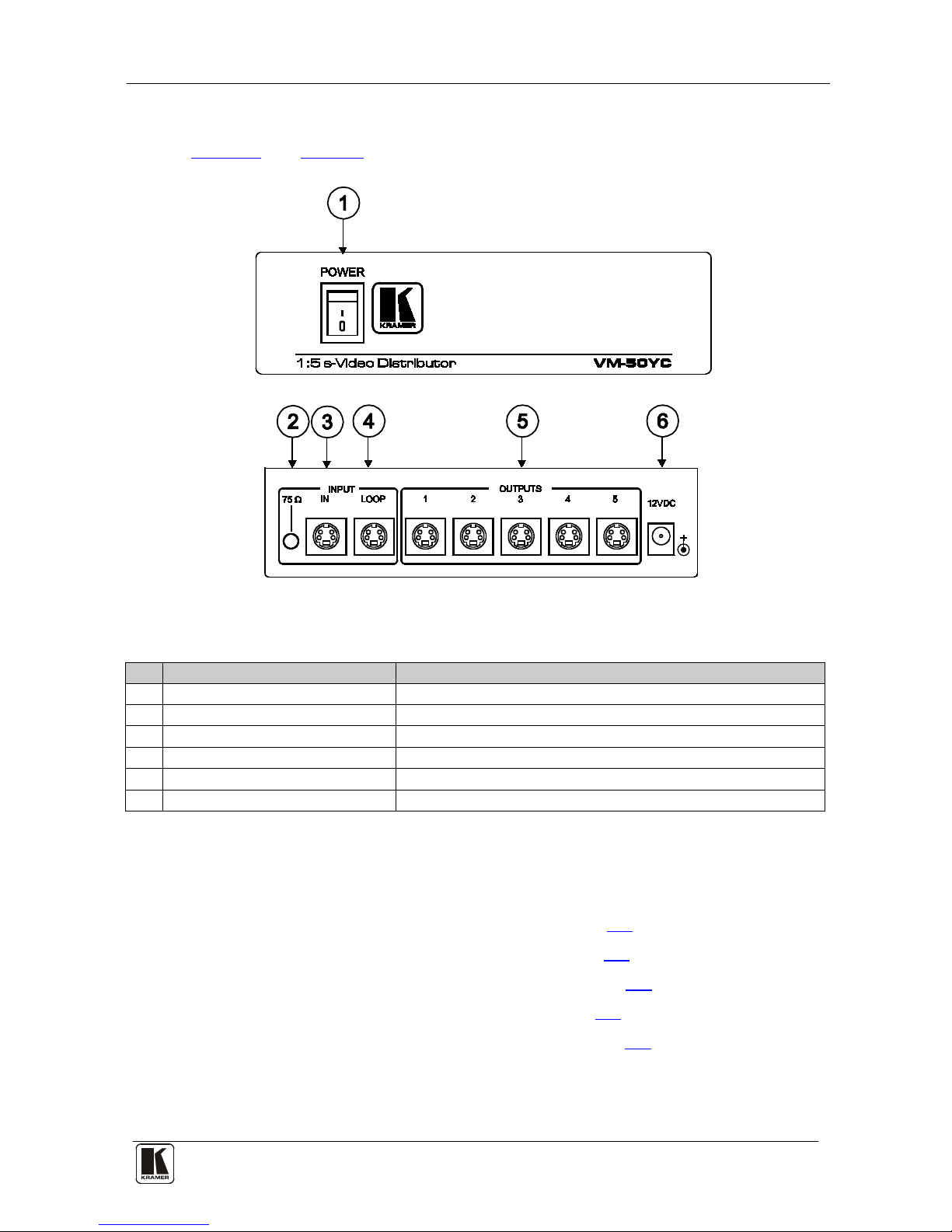
Figure 5 and Table 5 define the VM-50YC.
Figure 5: VM-50YC 1:5 s-Vi de o D is t ri butor
Table 5: VM-50YC 1:5 s-Video Distributor
#
Feature
Function
1 Illuminated Power Switch Illuminated switch for turning the unit ON or OFF
2 TERM Pushbutton Switch Press IN for 75Ω input termination, leave OUT for no termination
3 INPUT IN s-Video Connector Connects to the s-Video source
4 INPUT LOOP s-Video Connector Connects to an additional monitor
5 OUTPUTS s-Video Connectors Connect to the s-Video acceptors (from 1 to 5)
6 12V DC Connector Connects to the 12V DC power supply
5 Connecting the Distributors
This section describes how to connect the:
• VM-2N Video Audio Distr i butor , see section
5.1
• VM-5S Video Audio Distributor, see section
5.2
• VM-50HN Headphone Distributor, see section
5.3
• VM-50V 1:5 Video Distributor, see section
5.4
• VM-50YC 1:5 s-Video Distributor, see section
5.5
Page 15
KRAMER: SIMPLE CREATIVE TECHNOLOGY
Connecting the Distributors
12
5.1 Connecting the VM-2N Video Audio Distributor
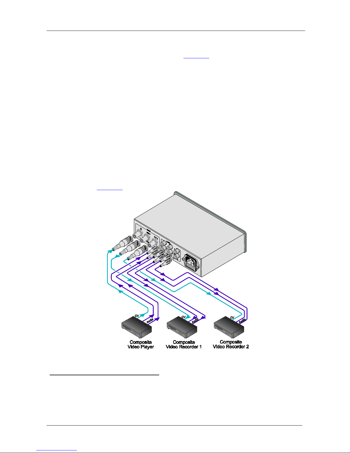
To connect the VM-2N, a s s hown in
Figure 6, do the following
1
1. Connect the input video source (for example, a composite video player) to
the VIDEO IN BNC connect or.
:
2. Connect th e in pu t au di o s our ce (for example, th e au di o fr om a c om pos it e
video player) to the AUDIO IN RCA connectors noting the right and left
channels.
3. Connect the VIDEO OUT 1 and 2 BNC connectors to up to 2 acceptors
2
4. Connect the AUDIO OUT 1 and 2 RCA connectors to up to 2 acceptors
(for example, composite video recorders).
2
(for example, the audio input on the composite video recorders).
5. Connect the power cord
3
6. If needed, adjust the LEVEL ands EQ controls on the underside of the unit
(see
to th e un it (not shown in th e illu str ation ) an d then
to the main s el ectrici ty . Switch on the power.
Figure 1).
Figure 6: Connecting the VM-2N Video Audio Distributor
1 Switch OFF the power on each device before connecting it to your VM-2N. After connecting, switch on the VM-2N power
and then switch on the power on each device
2 You are not required to connect two acceptors
3 Use the power cord supplied with the unit
Page 16
Connecting the Distributors
13 13
5.2 Connecting the VM-5S Video Audio Distributor
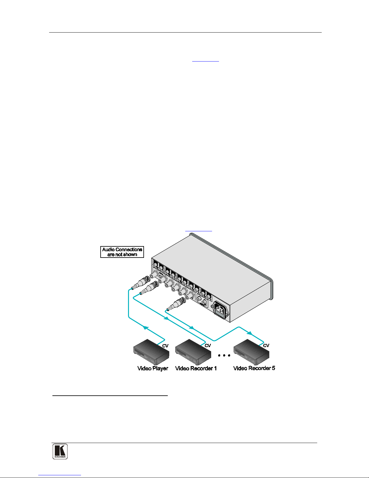
To connect the VM-5S, as shown in
Figure 7, do the following
1
1. Connect the input video source (for example, a video player) to the VIDEO
IN BNC connector.
:
2. Connect the input audio source (for example, the audio from the video
player) to the AUDIO IN RCA connectors noting the right and left
channels.
3. Connect the VIDEO OUT 1 to 5 BNC connectors to up to 5 acceptors
2
4. Connect the AUDIO OUT 1 and 5 RCA connectors to up to 5 acceptors
(for
example, video recorders).
2
(for example, the audio input on the video recorders).
5. For normal use (the input loop is not us ed), press IN the TERM pushbutton
to add a 75Ω termination to the line. If an input loop is used, release the
TERM pushbutton.
6. Connect the power cord
3
7. If needed, adjust the AUDIO LEVEL and VIDEO LEVEL and EQ con tr ols
on the underside of the unit (see
to th e un it (not shown in th e illu str ation ) an d then
to the mains electr icity. Swit ch on the power.
Figure 2).
Figure 7: Connecting the VM-5S Video Audio Distributor
1 Switch OFF the power on each de vice before connecting it to your VM-5S. After connecting, switch on the VM-5S power
and then switch on the power on each device
2 You are not required to connect all the acceptors
3 Use the power cord supplied with the unit
Page 17
KRAMER: SIMPLE CREATIVE TECHNOLOGY
Connecting the Distributors
14
5.3 Connecting the VM-50HN Headphone Distributor
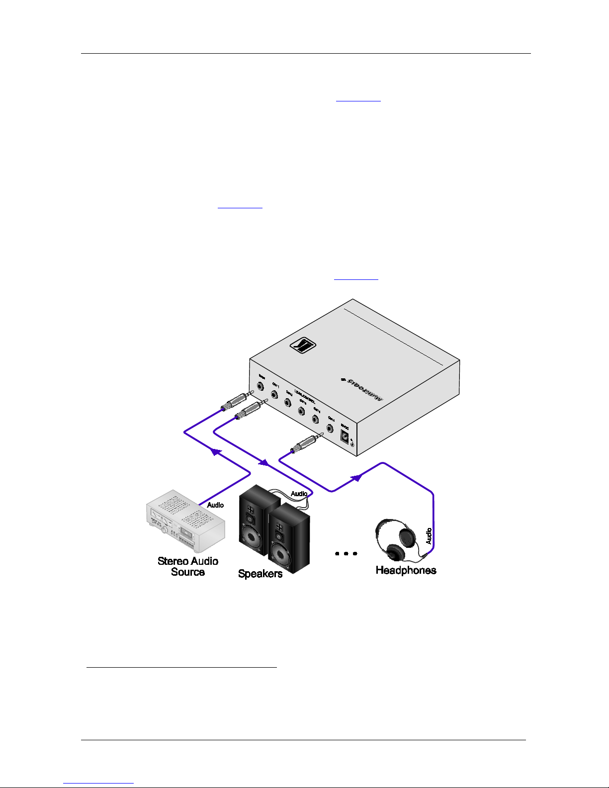
To connect the VM-50HN, as shown in
Figure 8, do the following
1
1. Connect the input audio source (for example, a stereo audio player) to the
INPUT 6.5mm phone connector.
:
2. Connect the OUT 1 to OUT 5 6.5mm phone connectors to up to 5
acceptors
2
3. Set the MONO pushbutton OUT for stereo operation and press IN for mono
operation (see
(f or exam ple, stereo headphones or speakers).
Figure 3).
4. Connect the 12V DC power supply to the unit (not shown in the illustration)
and th en t o th e m ain s el ec tri city . Sw it ch on the p ower .
5. Adjust the volume for each output using a small screwdriver to turn the
potentiometers on the front panel (see
Figure 3).
Figure 8: Connecting the VM-50HN Headphone Distributor
1 Switch OFF the power on each de vice before connecting it to your VM-50HN. After connecting, switch on the VM-50HN
power and then switch on the power on each device
2 You are not required to connect all the acceptors
Page 18
Connecting the Distributors
15 15
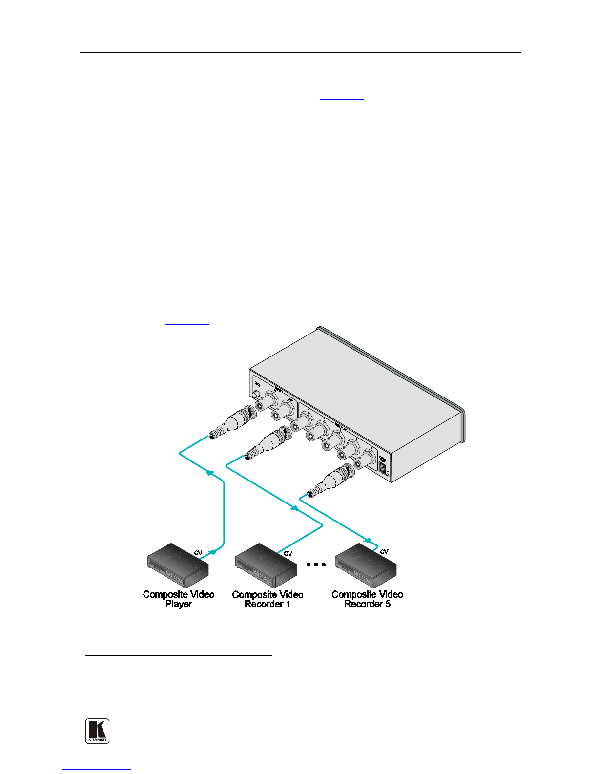
5.4 Connecting the VM-50V 1:5 Video Distributor
To connect the VM-50V, as shown in
Figure 9, do the following
1
1. Connect the input video source (for example, a composite video player) to
the INPUT IN BNC connector.
:
2. If looping the input to another device, connect a video acceptor (for example
a monitor) to the INPUT LOOP BNC connector.
3. If the input loop is not used, press IN the TERM pushbutton to add a 75Ω
termination to the line. If an input loop is used, release the TERM
pushbutton.
4. Connect the VIDEO OUT 1 to 5 BN C con nec tors to up t o 5 acceptors
2
5. Connect the 12V DC power supply to the unit (not shown in the illustration)
and then to the mains electr icity. Swit ch on the power.
(for
example, composite video recorders).
6. If needed, adjust the LEVEL and EQ controls on the underside of the unit
(see
Figure 4).
Figure 9: Connecting the VM-50V 1:5 Video Distributor
1 Switch OFF the power on each de vice before connecting it to your VM-50V. After conn ecting, switch on the VM-50V
power and then switch on the power on each device
2 You are not required to connect all the acceptors
Page 19
KRAMER: SIMPLE CREATIVE TECHNOLOGY
Connecting the Distributors
16
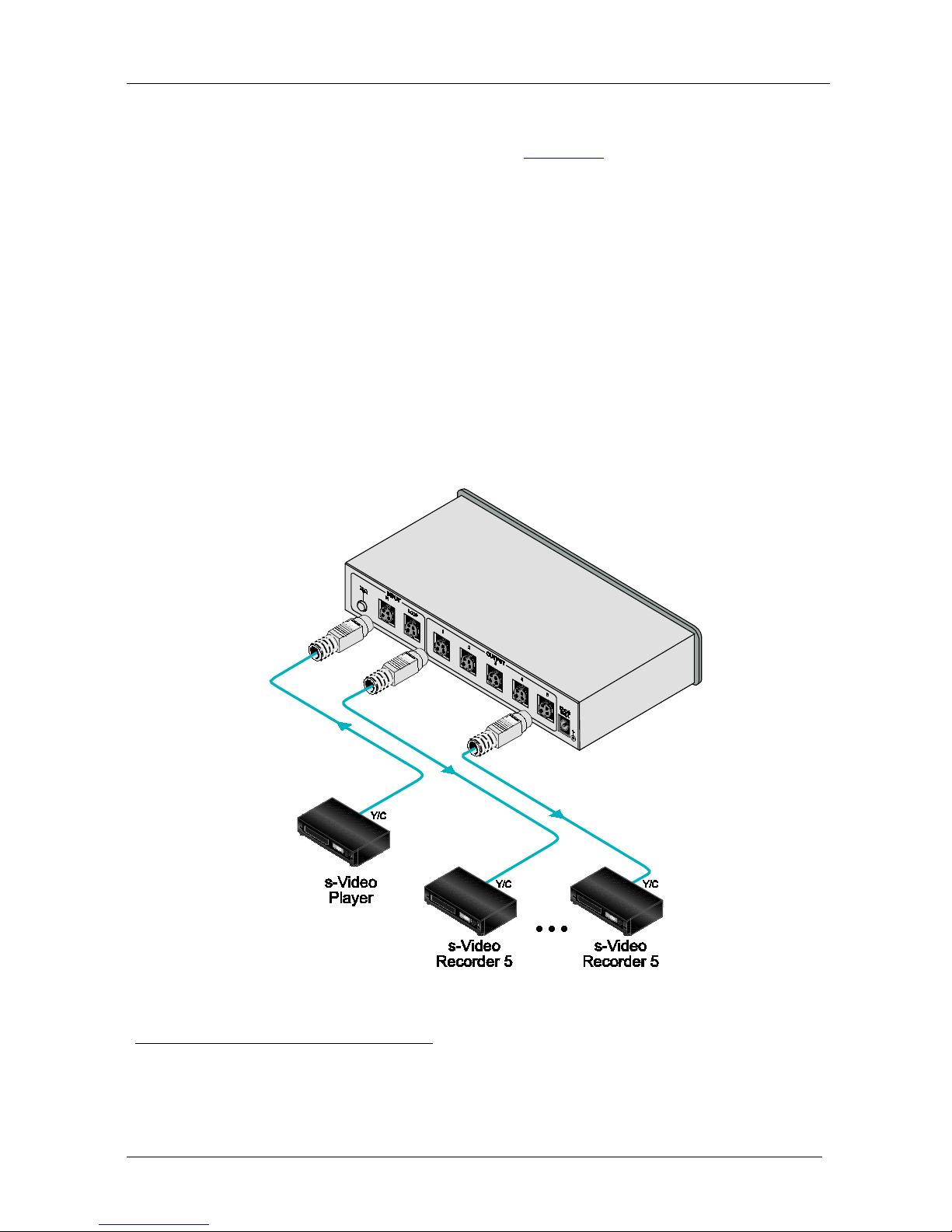
5.5 Connecting the VM-50YC 1:5 s-Video Distributor
To connect the VM-50YC, as shown in
Figure 10, do the following
1
1. Connect the input video source (for example, an s-video player) to the
INPUT IN s-video connector.
:
2. If looping the input to another device, connect a video acceptor (for example
an s-video monitor) to the INPUT LOOP s-video connector.
3. If the input loop is not used, press IN the TERM pushbutton to add a 75Ω
termination to the line. If an input loop is used, release the TERM
pushbutton.
4. Connect the OUTPUTS 1 to 5 s-video connectors to up to 5 acceptors
2
5. Connect the 12V DC power supply to the unit (not shown in the illustration)
and th en t o th e m ain s el ec tri city . Sw it ch on the p ower .
(for
example , s-video recorders).
Figure 10: Connecting the VM-50YC 1:5 s-Video Distributor
1 Switch OFF the po wer on each device before connecting it to your VM-50YC. After connecting, switch on the VM-50YC
power and then switch on the power on each device
2 You are not required to connect all the acceptors
Page 20
Technical Specifications
1717
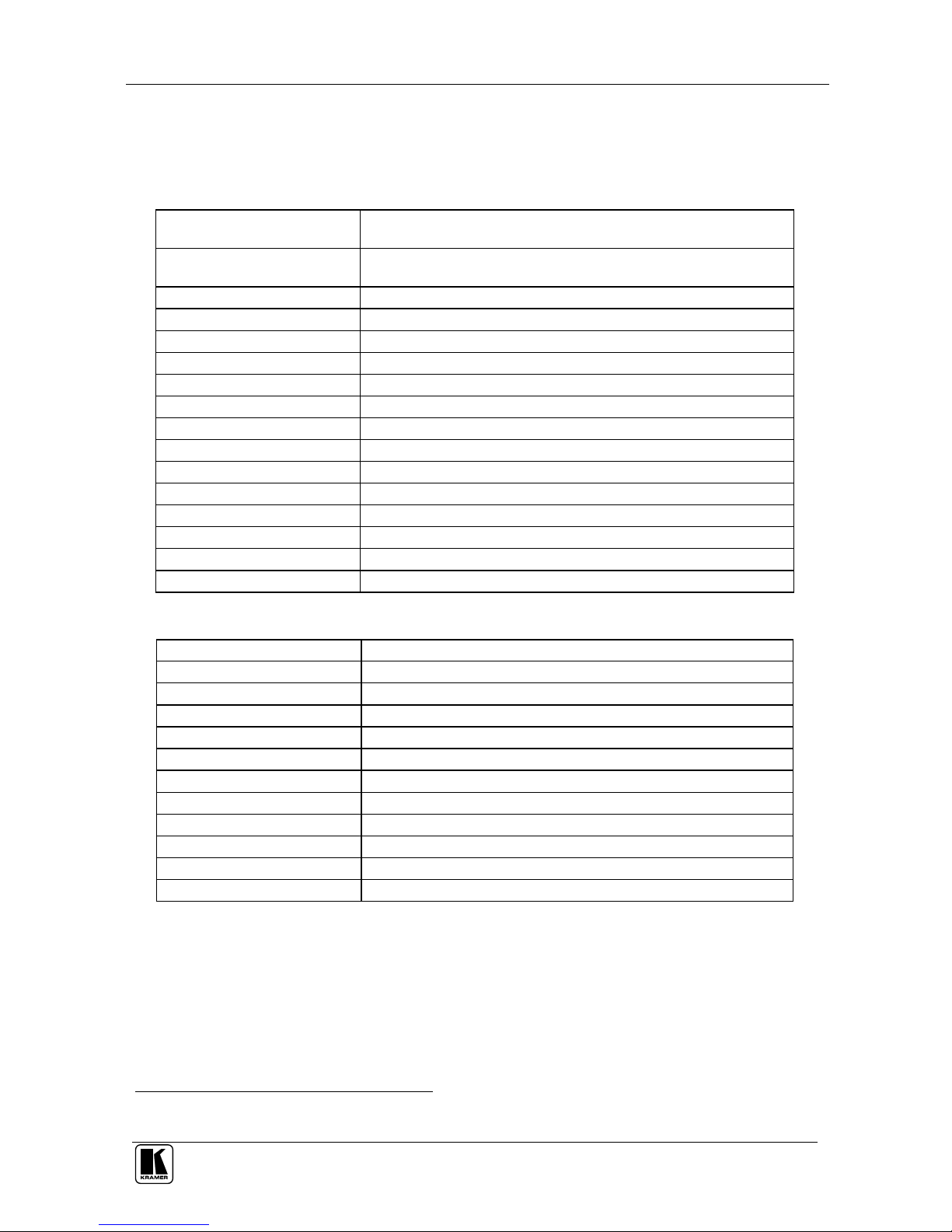
6 Technical Specifications
Tables 6 to 10 list technical specifications1 for the distributors:
Table 6: VM-2N Technical Specifications
INPUT: 1 composite video: DC coupled. 1Vpp/75 on a BNC connector;
1 audio: stereo/balanced mono. +4dBu/50k on RCA connectors
OUTPUT: 2 composite video: 1Vpp/75 on BNC connectors.
2 audio: stereo/balanced mono, +4dBu/50 on RCA connectors
MAX. AUDIO LEVEL (-3dB): 22dBu
VIDEO BANDWIDTH: Exceeding 400MHz
AUDIO BANDWIDTH: >100kHz (1dB)
DIFFERENTIAL GAIN: <0.05%
DIFFERENTIAL PHASE: 0.1Deg
K-FACTOR: <0.05%
S/N RATIO: Better than 85dB (audio) 75dB (video)
SDI EFF. RANGE: Up to 50 meters
AUDIO THD+N: 0.017%
POWER SOURCE: 230V AC/50Hz, (115V AC USA), 4.6VA
DIMENSIONS: 16.5cm x 12cm x 4.5cm (6.5" x 4.7" x 1.8") W, D, H
ACCESSORIES: Power cord
WEIGHT: 0.620kg (1.3lbs) approx
OPTIONS: RK-1 19" rack adapter
Table 7: VM-50HN Technical Specifications
INPUT: 1 audio stereo, 1Vpp/50k on a 6.5mm phone connector
OUTPUTS: 5 audio stereo, 500mW/8 on 6.5mm phone connectors
AUDIO BANDWIDTH (-3dB): 25kHz
CONTROL: 5 stereo output level controls (front), 1 mono switch (rear)
GAIN RANGE: -60dB to +10dB
S/N RATIO: 78dB
THD: 0.08% @100mW
POWER SOURCE: 12V DC, 370mA nom, 1A max
DIMENSIONS: 16.5cm x 12cm x 4.5cm (6.5” x 4.72” x 1.77”) W, D, H
WEIGHT: 0.68kg (1.5lbs) approx
ACCESSORIES: 12V DC power supply
OPTIONS: RK-13 19" rack adapter
1 Specifications are subject to change without notice
Page 21

KRAMER: SIMPLE CREATIVE TECHNOLOGY
Technical Specifications
18
Table 8: VM-5S Technical Specifications
INPUT: 1 video AC/DC coupled (internal ju mper), loo ping 1 Vpp/7 5
Ω on BNC
connectors with r ear ter min at ion swi tch;
1 audio stereo/ mono b al anced, up to 21 V/50 k
Ω on RCA connectors
OUTPUTS: 5 video, 1 Vpp/75 Ω on BNC connectors;
5 audio stereo/balanced mono, up to 21V/220 Ω on RCA connectors
MAX. VIDEO OUTPUT: 1.7 Vpp
VIDEO BANDWIDTH (-3dB): 340MHz
AUDIO BANDWIDTH (-3dB): 20kHz
DIFF. GAIN: 0.05%
DIFF. PHASE: 0.1Deg
K-FACTOR: 0.05%
VIDEO S/ N R ATI O: 75dB
AUDIO S/N: 82dB @1V
COUPLING: DC/A C internally selectable
AUDIO THD: 0.009%
SDI EFF EC TI VE RA NGE: Up to 70 meters
POWER SOURCE: 230V AC, 50/60Hz, (115V U.S .A.) 3.5V A
DIMENSIONS: 22cm x 18cm x 4.5c m (8 .7” x 7” x 1.8 ”) W, D, H (half 19”)
WEIGHT: 1.4kg (3.3lbs) approx
ACCESSORIES: Power cord
OPTIONS: RK-1 19" rack adapter
Table 9: VM-50V Technical Specifications
INPUT: 1 video, loop ing, 1 Vpp /75 Ω on BNC connectors with a termination
switch
OUTPUTS: 5 video, 1Vpp/75 Ω on BNC connectors
MAX. VIDEO OUTPUT: 2Vpp
VIDEO BANDWIDTH (-3dB): 480MHz
DIFF. GAIN: 0.05%
DIFF. PHASE: 0.12Deg
K-FACTOR: <0.05%
S/N RATIO: 73dB
CONTROL: 75Ω termination switch
COUPLING: AC
POWER SOURCE: 12V DC, 40mA
DIMENSIONS: 16.5cm x 12cm x 4.5 c m (6.5” x 4 .7” x 2. 8”) W, D, H
WEIGHT: 0.62kg (1.4lbs) approx
ACCESSORIES: 12V DC power supply, brackets for stacking multiple units
OPTIONS: RK-1 19" rack ad apt er
Page 22

Technical Specifications
19 19
Table 10: VM-50YC Technical Specifications
INPUT: 1 s-Video, looping: 1Vpp/75 Ω (Y), 0.3 Vpp/75Ω (C), on 4-pin
connectors with a te r minat ion switch
OUTPUTS: 5 s-Video: 1Vpp/75 Ω (Y), 0.3 Vpp/75Ω (C), on 4-pin connectors
MAX. VIDEO OUTPUT: 2Vpp (Y)
s-VIDEO BANDWIDTH (-3dB): 285M Hz ( Y)
DIFF. GAIN: 0.05%
DIFF. PHASE: 0.05Deg
K-FACTOR: 0.05%
S/N RATIO: 80dB
CONTROL: 75Ω termination switch
COUPLING: AC
POWER SOURCE: 12V DC, 50mA
DIMENSIONS: 16.5cm x 12cm x 4.5 c m (6. 5” x 4 .7” x 2.8”) W, D, H
WEIGHT: 0.58kg (1.3lbs) approx
ACCESSORIES: 12V DC power supply, brackets for stacking multiple units
OPTIONS: RK-1 19" rack adapter
Page 23

KRAMER: SIMPLE CREATIVE TECHNOLOGY
20
LIMITE D WA RRANTY
WHO IS PROTECTED?
WHA T IS COVERED AND WHA T IS NOT COVERE D
WHA T WE WILL P A Y FOR A ND WHA T W E WILL NOT P A Y FOR
HOW YOU CAN GET WARRANTY SERVICE
LIMITA TION OF IMPLIED WARRANTIES
EXCLUSION OF DAMAGES
CAUTION!
Kramer Electronics (hereafter ) warrants this product free from defects in material and workmanship under the
following terms.
Kramer
HOW LONG IS THE W ARRANTY
Labor and parts are warranted for seven years from the date of the first customer purchase.
Only the first purchase customer may enforce this warranty.
W e will p ay labor and ma teria l expen ses for cover ed item s. W e wi ll not pa y for th e foll owing:
The li abil ity of Krame r for any e ffe ct ive pr oduc ts is l imi ted t o the repair or re pla ceme nt of the pro duc t at ou r op tion. Kram er sha ll
not be liabl e for:
This wa rran ty give s you spec ific l egal rights , and yo u may al so have other r ights, w hich va ry fr om place to place.
All produ cts ret urned t o Krame r for service must hav e pri or approv al. This ma y be obt ained f rom you r deal er.
This e quipm ent has b een tes ted to determi ne co mpliance with t he requ ireme nts of:
EN-50 081: "Electro magnet ic com patibi lity ( EMC);
generic emission standard.
Residenti al, co mmerc ial and l ight ind ustry "
EN-50 082: "Electro magnet ic com patibi lity ( EMC) gen eric i mmunity stand ard.
Part 1 : Reside ntia l, comm ercial and lig ht indus try e nviro nment".
CFR-47: FCC* Rules and Regulations:
Part 15 : “Ra d io frequency devices
Subpart B Unintentional radiators”
Except as below, this warranty covers all defects in material or workmanship in this product. The following are not covered
by the warranty:
1. Any product which is not distributed by Kramer, or which is not purchased from an authorized Kramer dealer. If you are
uncertain as to whether a dealer is authorized, please contact Kramer at one of the agents listed in the Web site
www.kramerelectronics.com.
2. Any product, on which the serial number has been defaced, modified or removed, or on which the WARRANTY VOID
TAMPERED sticke r ha s be e n to r n,
3. Damage, deterio ratio n or ma lfuncti on resu lting from:
i) Accident, misuse, abuse, neglect, fire, water , ligh tning o r other acts of nature
ii) Product m odifi cation , or fai lure to f ollow instru ction s suppli ed wit h the pr oduct
iii) Repair or attemp ted re pair by a nyone n ot auth oriz ed by Kra mer
iv) Any ship ment o f the pr oduct ( claim s must b e presen ted to the carr ier)
v) Remo val or i nstall ation of the produc t
vi) Any other cause, which does not relate to a product defect
vii)Cartons, e quipm ent encl osure s, cabl es or accesso ries use d in c onjunc tion wi th the p roduct
1. R emoval or inst alla tions c harges .
2. Costs of initial technical adjustments (set-up), including adjustment of user controls or programming. These costs are the
respon sibi lity of the Kram er deal er fr om whom t he produ ct wa s purcha sed.
3. Shipp ing char ges .
1. To obtain service on you product, you must take or ship it prepaid to any authorized Kramer service center.
2. Whenever warranty service is required, the original dated invoice (or a copy) must be presented as proof of warranty
coverage, and should be included in any shipment of the product. Please also include in any mailing a contact name,
company, address, and a description of the problem(s).
3. For the name of the nearest Kramer authorized service center, consult your authorized dealer.
All implied warranties, including warranties of merchantability and fitness for a particular purpose, are limited in duration to
the length of this warranty.
1. Damag e to other prop erty cau sed by def ects in this product , damage s based upon inc onven ience , loss of use of the produc t, los s
of time, commercial lo ss; o r:
2. Any ot her dam ages , w het her i nci den tal, conse que nti al o r o the rwise . S ome c oun tri es ma y n ot a llow lim ita tion s on ho w lon g a n
implied warranty lasts and/or do not allow the exclusion or limitation of incidental or consequential damages, so the above
limit ation s and exc lusio ns may no t apply to yo u.
Servicing the machines can only be done by an authorized Kramer technician. Any user who makes changes or
modifications to the unit without the expressed approval of the manufacturer will void user authority to operate the
equipment.
Use th e suppl ied DC p ower sup ply t o feed p ower to t he mach ine.
Please use recommended interconnection cables to connect the machine to other components.
IF reattached, removed or otherwise interfered with.
* FCC and CE appro ved usin g STP cable ( for twist ed pai r product s)
NOTE:
Part 1 :
Page 24

Kramer Electronics, Ltd.
Web site: www.kramerelectronics.com
E-mail: [email protected]
P/N: 2900-000535 REV 3
For the latest information on our products and a list of Kramer
distributors, visit our Web site: www.kramerelectronics.com
where updates to this user manual may be found.
We welcome your questions, comments and feedback.
Caution
Safety Warning:
Disconnect the unit from the power supply before
opening/servicing.
PN:
2900- 000535
Rev:
3
 Loading...