


KRAMER ELECTRONICS, Ltd.
USER MANUAL
Video/Audio Distribution Amplifiers
Models:
VM-2N, VM-5S, VM-50A,
VM-50H, VM-50V, VM-50YC
IMPORTANT: Before proceeding, please read paragraph entitled
"Unpacking and Contents"
KRAMER ELECTRONICS LTD.

Table Of Contents
Section Name Page
11
13
13
13
13
14
14
14
16
16
17
19
1
1
1
2
6
6
7
8
9
1 INTRODUCTION
1.1
1.2
2
3
4
4.1
5
5.1
5.2
5.3
5.4
5.5
5.6
6
7
8
9
9.1
9.2
9.3
9.4
9.5
9.6
10
11
11.1
11.2
11.3
A Word On Distribution Amplifiers
Factors Affecting Quality of Results
Specifications
How Do I Get Started? 4
Unpacking and Contents 4
Optional Accessories 4
VM Series Amplifiers
Getting To Know Your VM-2N
Getting To Know Your VM-5S Amplifier
Getting To Know Your VM-50A Amplifier
Getting To Know Your VM-50H Amplifier
Getting To Know Your VM-50YC Amplifier
Getting To Know Your VM-50V Amplifier 12
INSTALLATION 13
Connecting To VIDEO Devices 13
Connecting To audio Devices
Using The VM VIDEO/AUDIO AMPLIFIERS
Powering On The Amplifier
Looping
Coupling
Coupling Selection
Audio Level Control
Installing a VM Amplifier In a Mixed AC/DC Video/Audio System 15
Taking Care Of Your Amplifier 16
TROUBLESHOOTING
Power And Indicators
Audio Signal
Video Signal
List Of Illustrations
Figure Page
VM-2N Front/Rear Panel Features
1
2
VM-5S Front/Rear Panel Features
3
4
5
6
VM-50V Front/Rear Panel Features
7
J2 Internal Jumper Location 14
Installing a VM Amplifier In a Mixed AC/DC Video/Audio System
8
9
VM-50A Front/Rear Panel Features 9
VM-50H Front/Rear Panel Features
VM-50YC Front/Rear Panel Features 11
Locating The Internal Fuses
Table
1
2 VM-5S Front/Rear Panel Features 8
3 VM-50A Front/Rear Panel Features 9
4
5
6 VM-50YC Front/Rear Panel Features 12
7 VM-50V Front/Rear Panel Features 13
KRAMER ELECTRONICS LTD.
VM-2N Front/Rear Panel Features
VM-50H Front Panel Features
VM-50H Rear Panel Features
10
12
List Of Tables
7
11
11
1
15
18
7
8

1. INTRODUCTION
Congratulations on your purchase of this Kramer Electronics amplifier. Since 1981 Kramer has
been dedicated to the development and manufacture of high quality video/audio equipment.
The Kramer line has become an integral part of many of the best production and presentation
facilities around the world. In recent years, Kramer has redesigned and upgraded most of the
line, making the best even better. Kramer’s line of professional video/audio electronics is one of
the most versatile and complete available, and is a true leader in terms of quality, workmanship,
price/performance ratio and innovation. In addition to the Kramer line of high quality amplifiers,
such as the one you have just purchased, Kramer also offers a full line of high quality switchers,
processors, interfaces, controllers and computer-related products. This manual includes
configuration, operation and option information for the following products from the Kramer VM
line of distribution amplifiers. All these VM amplifiers are similar in operation and features.
VM-2N- 1:2 Video/Audio Distributor
VM-5S- 1:5 Video/Audio Distributor
VM-50A- 1:5 Audio Distributor
VM-50H- 1:5 Headphone Distributor
VM-50V- 1:5 Video Distributor
VM-50YC-1:5 s-Video Distributor
1.1 A Word On Distribution Amplifiers
Distribution amplifiers are used to distribute one source to several acceptors for simultaneous
recording or monitoring of one source, with no discernible signal degradation. They vary in the
number of inputs, looping capability, programming capability, number of outputs, operating
format, bandwidth and input/output coupling. A good quality distribution amplifier amplifies
the incoming signal, pre-compensates the signal for potential losses (resulting from the use of
long cables, noisy source, etc.) and generates several identical buffered and amplified outputs.
1.2 Factors Affecting Quality of Results
There are many factors affecting the quality of results when signals are transmitted from a
source to an acceptor:
Connection cables
- Low quality cables are susceptible to interference, they degrade signal
quality due to poor matching and cause elevated noise levels. They should therefore be of the
best quality.
Sockets and connectors of the sources and acceptors
- So often ignored, they should be of
highest quality, since "Zero Ohm" connection resistance is the target. Sockets and connectors
also must match the required impedance (75 ohms in video). Cheap, low quality connectors
tend to rust, thus causing flaws in the signal path.
Amplifying circuitry
- Must have quality performance when the desired end result is high
linearity, low distortion and low noise operation.
Distance between sources and acceptors
- Plays a major role in the final result. For long
distances (over 15 meters) between sources and acceptors, special measures should be taken in
order to avoid cable losses. These include using higher quality cables or adding line amplifiers.
Interference from neighboring electrical appliances
- These can have an adverse effect on signal
quality. Balanced audio lines are less prone to interference, but unbalanced audio should be
installed far from any mains power cables, electric motors, transmitters, etc. even when the
cables are shielded.
KRAMER ELECTRONICS LTD.
1
t
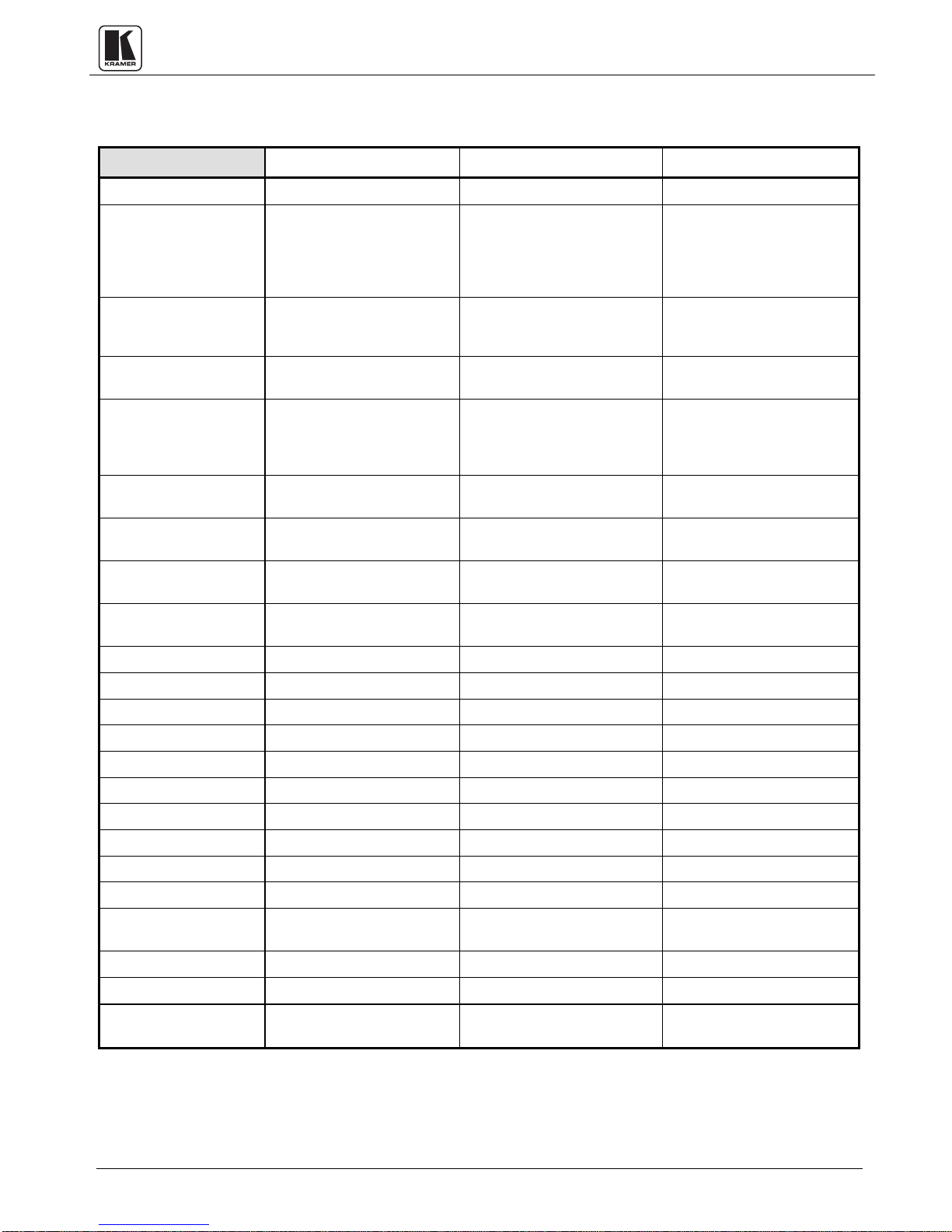
2. SPECIFICATIONS
VM-2N VM-5S VM-50A
Configuration
Input Type
Input Connections
Input Level
Output Type
Output Connector
Output Level
Output Coupling
S/N Ratio
Audio Bandwidth
Video Bandwidth
Max audio Output
Max video Output
Differential Gain
Differential Phase
Audio THD+N
Second harmonic
K-Factor
SDI eff. Range
Dimensions (W, D, H)
Weight
1:2 1:5 1:5
1 Composite/single
component video
1 stereo audio/balanced
mono
BNC connector (video)
RCA connector (audio)
1Vpp/75ohm (video)
+4dBm/50kohm (audio)
2 video
2 stereo audio/balanced
mono
BNC connector (video)
RCA connector (audio)
1Vpp/75 (video)
+4dBm/50ohm (audio)
DC (video)
AC (audio)
Better than 85dB(audio)
75dB (video)
>100KHz, 0 -1db points 100 kHz 50khz, -3db
Exceeding 400 MHz. Exceeding 350 MHz. NA
>24dBm +20dBm 25Vpp
1.5Vpp 1.7Vpp NA
0.05% 0.05% NA
0.1Deg. 0.1Deg. NA
0.017% 0.009% <0.018%
0.002% @ 1KHz 0.001% @ 1KHz 0.003%
<0.05% <0.05% NA
Up to 50 meters Up to 70 meters NA
16.5cm x 12cm x 4.5cm
6.5" x 4.72" x 1.77"
0.620Kg (1.3lbs) Approx. 1.40Kg (3.3lbs.) Approx. 0.62Kg (1.4lbs) Approx.
1 video (internally selected)
looping (composite, single
component or serial digital)
1 stereo audio/balanced
mono
BNC connector with rear
ermination switch (video)
RCA connector (audio)
1Vpp/75ohm on (video)
up to 21V/50kohm (audio)
5 video (composite, single
component or serial digital)
5 stereo audio/balanced
mono
BNC connector (video)
RCA connector (audio)
1Vpp/75ohm (video)
up to 21V/220ohm (audio)
DC/AC internally selectable AC
> 82dB @ 1V (audio)
75dB (video)
22cm x 18cm x 4.5cm
8.66" x 7.08" x 1.77"
1 stereo audio
RCA
Looping +4dbm/50kohm
5 stereo audio
RCA connectors
+4dBm/100ohm
83db unweighted
16.5cm x 12cm x 4.5cm
6.5" x 4.72" x 1.77"
Power consumption
Power Source
4.6VA 3.5VA 0.78VA
230VAC/50Hz, (115V
USA)
KRAMER ELECTRONICS LTD.
230VAC, 50Hz, (115V
USA)
2
12VDC, 40mA
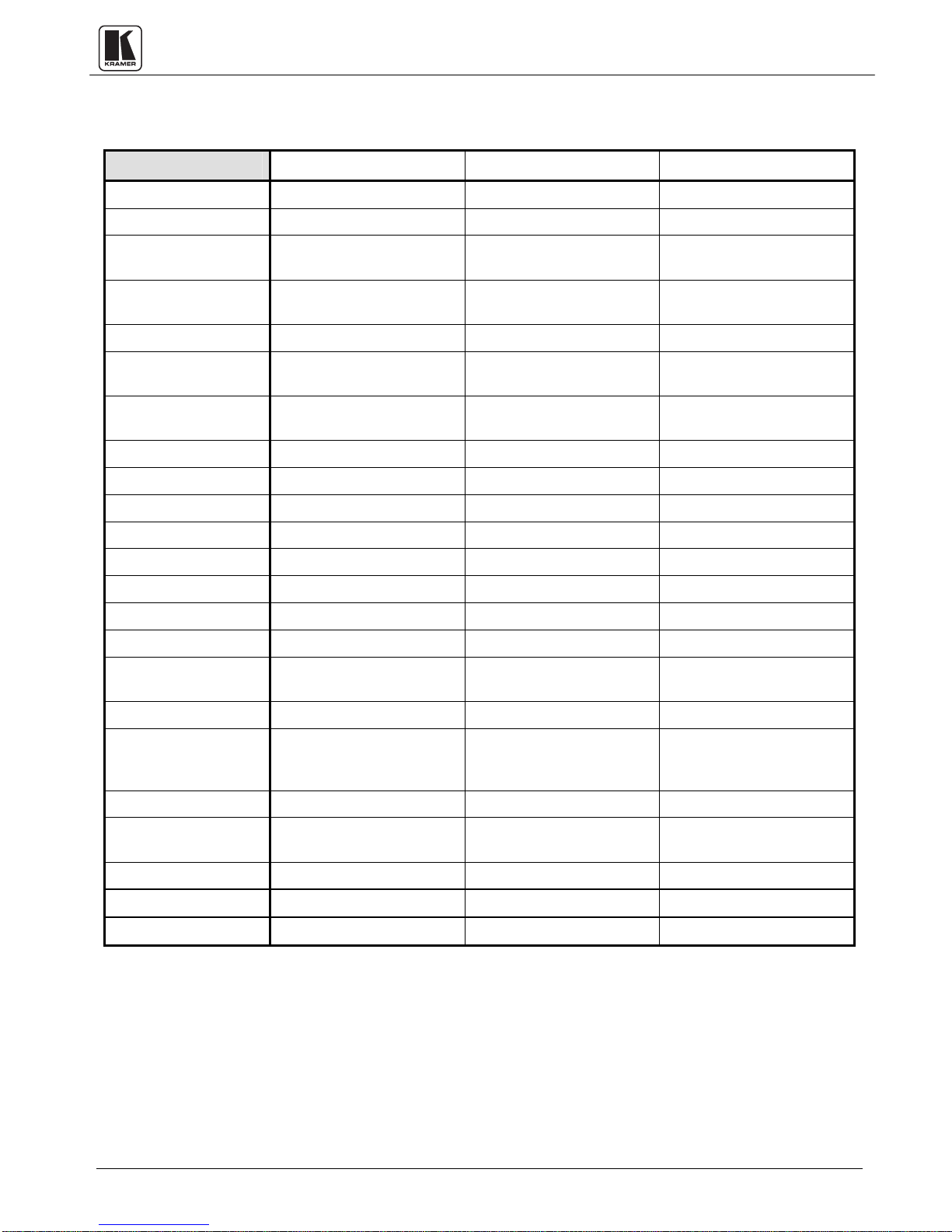
SPECIFICATIONS (continued)
VM-50H VM-50YC VM-50V
Configuration
Input Type
Input Connections
Input Level
Output Type
Output Connector
Output Level
Output Coupling
S/N Ratio
Audio Bandwidth
Video Bandwidth
Max audio Output
Max video Output
Differential Gain
Differential Phase
1:5 1:5 1:5
1 stereo audio 1 s-video, looping 1 video, looping
6.5-mm stereo phone
sockets
1Vpp/50kohm 1Vpp/75ohm (Y),
5 stereo audio 5 s-video, looping 5 video
6.5-mm stereo phone
sockets
250mW/8ohm 1Vpp/75ohm (Y),
AC AC AC
Better than 78dB 80.5dB 73db
20-100,000 Hz. -3dB NA NA
NA 280 MHz -3dB (Y) 480MHz -3dB
8Vpp NA NA
NA 2Vpp (Y) 2Vpp
NA 0.05% 0.05%
NA 0.05Deg 0.12Deg
4P connectors with a
termination switch
0.3Vpp/75ohm (C)
4P connectors BNC connectors
0.3Vpp/75ohm (C)
BNC connector with
termination switch
1Vpp/75ohm
1Vpp/75ohm
Audio THD+N
K-Factor
Level Controls
Gain Range
Dimensions
(
W, D, H)
Weight
Power consumption
Power Source
Less than 0.08% @
100mW
NA <0.1% <0.05%
5 stereo output level
controls (front), 1 mono
switch (rear)
70db (-60db to +10db) -1.6 to 3.3dB -0.8 to 1.9dB
16.5cm x 12cm x 4.5cm
6.5" x 4.72" x 1.77"
0.68Kg (1.5lbs) 0.58Kg (1.3lbs.) 0.62Kg (1.4lbs.)
15VA 0.6VA 0.48VA
12VDC, 1.15A 12VDC, 50mA 12VDC, 40mA
NA NA
Y control: Range: -1.6 to
3.3db
C Control: -1.6 to 3.3db
16.5cm x 12cm x 4.5cm
6.5" x 4.72" x 1.77"
Gain Range = -0.8 to 1.9db
EQ. control: 0 to 3.2db
16.5cm x 12cm x 4.5cm
6.5" x 4.72" x 1.77"
KRAMER ELECTRONICS LTD.
3

3. HOW DO I GET STARTED?
The fastest way to get started is to take your time and do everything right the first time. Taking
15 minutes to read the manual may save you a few hours later. You don’t even have to read the
whole manual. At the beginning of each section, you’ll find an overview of the section. So if the
section doesn’t apply to you, you don’t have to spend your time reading it.
4. UNPACKING AND CONTENTS
The items contained in your Kramer VM amplifier package are listed below. Please save the
original box and packaging materials for possible future transportation and shipment of the
amplifier.
Desktop size amplifier
AC power cable (where applicable)
User’s Manual
Rubber feet
Kramer concise product catalog
For additional information regarding optional cables and additional accessories, contact your
Kramer dealer.
Optional Accessories
4.1
The following Kramer accessories can enhance implementation of your amplifier.
Rack Adapter - Used to adapt non-standard size machines to a standard 1U rack. One or
more machines may be installed on each adapter.
BNC "Y" Connector - Used for looping purposes and splits the incoming signal to enable
connection of an additional machine.
Termination Plug - Used to terminate the line to 75ohm for proper matching.
SP-40 - (video/audio Processor) Serially connected between the video/audio source and
the VM amplifier for video and audio processing. The machine is a high quality processor
used for video control and correction in duplication and production studios, camera control,
luminance and white balance correction. The SP-40 is capable of Composite to Y/C
conversion and bi-directional transcoding. The machine allows video gain control down to full
fade, definition control, contrast control, color saturation control, black level control, audio
mix control for mixing between the selected source and an audio AUX source and a screen
splitter control for “before-after” comparison. The unique limiter switch in the SP-40 allows
true signal limiting and special effects.
SP-11 - (video/audio Processor) can be serially connected between the video/audio source
and the VM amplifier for video and audio control/correction. The machine provides camera
control and luminance/white balance correction. The SP-11 is also capable of performing
composite to Y/C conversion and bi-directional transcoding. The machine allows full control
over the video signal: video gain down to full fade, log or linear definition control, log or
linear contrast control, color saturation control, black level control, red, green and blue
controls and a screen splitter control for “before-after” comparison. The Input switch control
is "audio-follow-video".
KRAMER ELECTRONICS LTD.
4

104L - (video Line Amplifier) Serially connected between the video source and the VM
amplifier for video processing, the machine is used for video line amplification and cable
compensation, video field work and SDI signal distribution. Signal loss and the resulting
depreciation in picture quality is a real problem in any video setup requiring considerable
distance between video source and acceptors. The KRAMER 104L video Line Amplifier, one
of the KRAMER TOOLS, is a high quality amplifier, which prevents video signal losses over
long cables. For best results the 104L amplifier is installed adjacent to the video source. The
104L is housed in the compact KRAMER TOOLS enclosure and is fed by a 12VDC source.
High bandwidth and front accessible controls make it suitable for the most demanding analog
and SDI studio applications.
VM-9YC - (video/audio Line Amplifier) Serially connected between the video/audio
source and the VM amplifier for video and audio processing, the machine is a high quality
video/stereo amplifier which compensates for video and audio signal losses when long cables
are used. In any video/audio setup requiring considerable distances between video/audio
source and acceptors, signal loss and thus depreciation in the quality of both picture and
sound is a real problem. To prevent this phenomenon, a VM-9S amplifier is installed adjacent
to the video/audio source.
VM-4E - (A Precision Mechanical 4x4 video/audio Switcher) Several video/audio sources
may be connected to its inputs for switching. The machine may be used in every application
where easy and fast video and audio source selection is needed and for high isolation between
inputs. All unselected inputs are internally terminated with 75-Ohm resistors. The VM-4E
switches video, SDI and any other high frequency signals. The VM-4E is housed in a small
enclosure, occupying very little desk space.
VM-81AV - (A Precision Mechanical 8x1 video/stereo audio Switcher) Several
video/audio sources may be connected to its inputs for switching. The machine offers fast
and easy video/audio source and acceptor selection. The VM-81AV provides high isolation
between inputs and outputs and all unselected video inputs are internally terminated with
75-Ohm resistors. The VM-81AV is housed in a professional 19" rack mountable enclosure.
VS-801xl- (8:1 Composite/Single Component video & Unbalanced audio Switcher)
Several video/audio sources may be connected to its inputs for switching. The machine
provides truly effortless switching between eight video and unbalanced audio inputs and one
output. Switching is done during vertical interval, either of source no. 1 or of the video
available on the external sync socket. The switcher may be controlled by touch buttons or by
contact closure via a remote socket on the back of the machine. video signal bandwidth is 225
MHz (typical), allowing the machine to be used in the most demanding applications.
TP-1 (video Line Transmitter) If a DA output is sent over a long distance (100 meter or
more), it is necessary to convert the signal to twisted pair type. The TP-1 sends a color video
signal over long distances using telephone wire or any other twisted pair wire thus extending
the range of operation of a DA. The TP-1 maintains the bandwidth of an industrial color
video signal up to several hundred meters and of broadcast quality (up to 12 MHz) signals up
to 100 meters. At shorter distances, as in a studio, bandwidth of 30MHz is easily achieved.
By using the KRAMER TP-1 together with the TP-2 (video Line Receiver) coax wiring (in a
studio, for example) can be completely eliminated. The TP-1 can also be used for
KRAMER ELECTRONICS LTD.
5

simplification of security and CCTV installations, and for teleconferencing in offices and
hospitals using existing intercom or telephone wiring.
VA-11AV - (video/audio Combiner) Used to distribute video/audio signals. The machine
can be inserted in front of a DA, allowing the DA to distribute a video signal and two audio
signals simultaneously. It sends a color video signal and a stereo audio signal using only one
standard coax cable in real time. The machine maintains the bandwidth of an industrial color
video signal and the output signal may be viewed and recorded as a normal video signal. By
using the VA-11AV together with the VA-12AV (video/audio Separator) the audio stereo
signal may be recovered so audio signals may be sent in a hidden mode, to be recovered only
by the VA-12AV. The VA-11AV can be used for simplification of security and CCTV
installations, using existing video coax wiring for video and audio transmissions.
611T/611R - (611T Fiber Optic Transmitter and 611R Fiber Optic Receiver) Part of the
KRAMER TOOLS series, and designed for studio and other demanding applications, these
machines, in combination, may be used to send one of the distributed channels to distances
of 5-25Km. The full bandwidth 611T and matching 611R use state-of-the-art fiber optic
circuitry and allow the user (via rear panel trimmers) to adjust input and output video levels
and high frequency peaking to achieve best performance.
VIDEO TESTER - A new, unique, patented, indispensable tool for the video professional,
the video Tester is used to test a video path leading to/from an amplifier. By pressing only
one touch switch it can trace missing signals, distinguish between good and jittery (VCR
sourced) signals, and identify the presence of good signals. Whenever a video signal is missing,
because of bad connections, cable breaks or faulty sources, the video Tester is all you need.
VM SERIES AMPLIFIERS
5.
This section describes all the controls and connections of your amplifier. Understanding all of
the controls and connections helps you realize its full power.
5.1 Getting To Know Your VM-2N
The KRAMER VM-2N is an ultra-high bandwidth, state-of-the-art video/stereo audio
Distribution Amplifier designed for analog and digital studio applications. The VM-2N splits a
single input source, be it composite, single component or Serial Digital video, into two identical
outputs with no discernible signal degradation. video output signals are DC coupled. The audio
can be either unbalanced stereo or balanced mono, as the audio performance and levels of the
VM-2N are appropriate for use in the most demanding applications.
Front/Rear panel features of the VM-2N are described in Figure
1 and Table 1.
NOTE
For operation instructions refer to section 9.1.
KRAMER ELECTRONICS LTD.
6
 Loading...