

Page 1

Kramer Electronics, Ltd.
USER MANUAL
Models:
VM-28H, 2 Input 1:8 HDMI Distributor
VM-216H, 2 Input 1:16 HDMI Distributor
Page 2

Contents
i
Contents
1 Introduction 1
2 Getting Starte d 1
2.1 Quick Start 2
3 Overview 3
3.1 About HDMI 4
3.2 Defining EDID 5
3.3 Recommendations for Best Performance 5
4 Your VM-28H / VM-216H 5
4.1 Using the IR Transmitter for the VM-28H 9
5 Installing in a Rack 10
6 Using the VM-28H / VM-216H 11
6.1 Connecting the VM-28H / VM-216H 11
6.1.1 Connecting the VM-28H 2 Input 1:8 HDMI Distributor 11
6.1.2 Connecting the VM-216H 2 Input 1:16 HDMI Distributor 13
6.2 Connecting to the VM-28H / VM-216H via RS-232 14
6.3 Operating the VM-28H / VM-216H 14
6.4 Using the EDID Button 14
6.4.1 Acquiring / Changing the EDID from one Output 15
6.4.2 Acquiring the Default EDID 16
6.4.3 Acquiring the EDID from several Outputs 16
7 Technical Specifications 17
8 Communication Protocol 18
Figures
Figure 1: VM-28H 2 Input 1:8 HDMI Distributor 6
Figure 2: VM-216H 2 Input 1:16 HDMI Distributor
7
Figure 3: Connecting a VM-28H 2 Input 1:8 HDMI Distributor 12
Figure 4: Connecting a VM-216H 2 Input 1:16 HDMI Distributor
13
Tables
Table 1: VM-28H / VM-216H Features 8
Table 2: The EDID Modes
15
Table 3: VM-28H Technical Specifications
17
Table 4: VM-216 H Technical Specifications
17
Table 5: Protocol Definitions 18
Table 6: Instruction Codes for Protocol 2000
19
Page 3

Introduction
1
1 Introduction
Welcome to Kramer Electronics! Since 1981, Kramer Electronics has been
providing a world of uni que, creat iv e, an d aff ordabl e s oluti ons to t h e vast range
of problems that confr ont vi deo, au di o, pres enta ti on, and broadcas t ing
professionals on a daily basis. In recent years, we have redesigned and
upgraded most of our line, making the best even better! Our 1,000-plus
different models now appe ar in 11 gr ou ps
1
Congratulations on purchasing your Kramer VM-28H 2 Input 1:8 HDMI
that are clearly defined by function.
2
• Home theater, presentation and multimedia applications
Distributor and/or VM-216H 2 Input 1:16 HDMI Distributor! Each machine is
ideal for:
• Rental and staging
The package includes the following items:
• VM-28H and/or VM-216H
• Power cord and rack “ears”
• Infrared remote control transmitter (including the required batteries and a
separate user manual
3
)
• This user manua l
3
2 Getting Started
We recommend that you:
• Unpack the equipment carefully and save the original box and packaging
materials for possible future shipment
• Review the contents of this user manual
• Use Kramer high performance high resolution cables
4
1 GROUP 1: Distribution Amplifiers; GROUP 2: Switchers and Routers; GROUP 3: Control Systems;
GROUP 4: Format/Standards Converters; GROUP 5: Range Extenders and Repeaters; GR OUP 6: Specialty AV Products;
GROUP 7: Scan Converters and Scalers; GROUP 8: Cables and Connectors; GROUP 9: Room Connectivity;
GROUP 10: Accessories and Rack Adapters; GROUP 11: Sierra Products
2 High-Definition Multimedia Interface
3 Download up-to-date Kramer user manuals from the Internet at this URL: http://www kramerelectronics com
4 The complete list of Kramer cables is on our Web site at http://www kramerelectronics com
Page 4
KRAMER: SIMPLE CREATIVE TECHNOLOGY
Getting Started
2
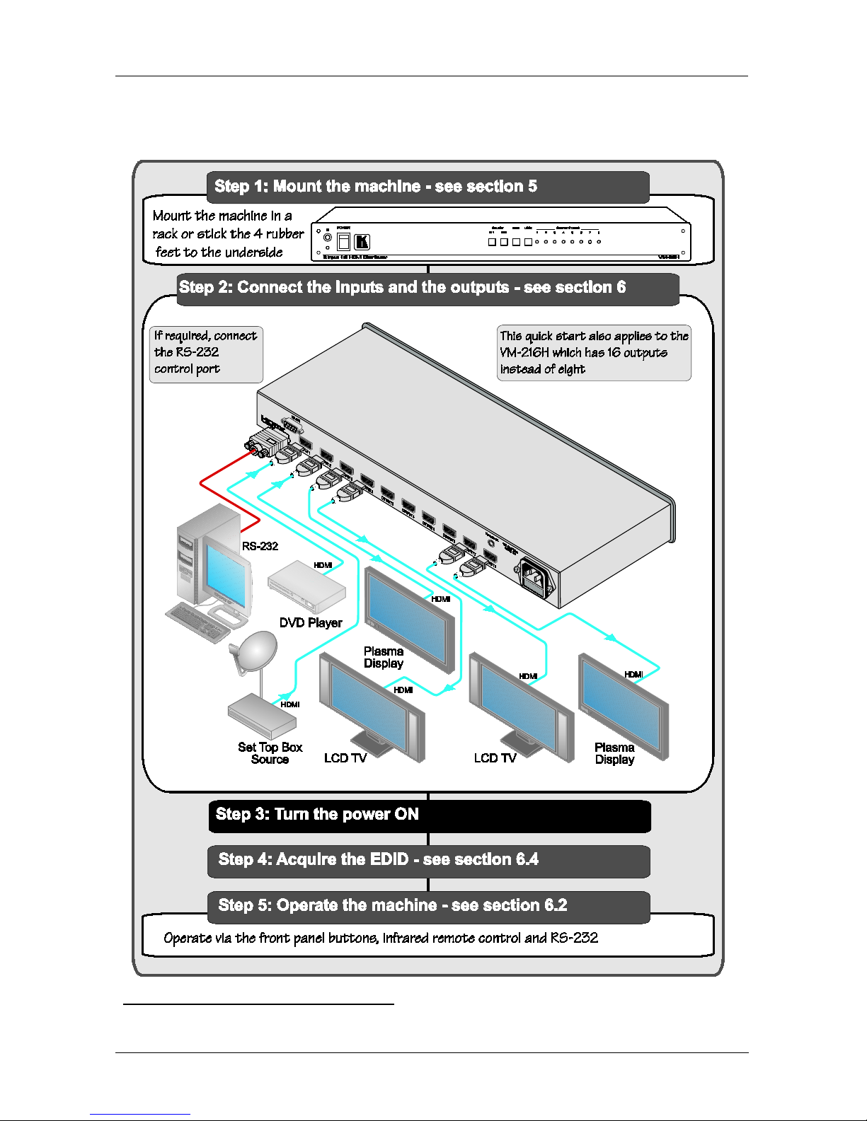
2.1 Quick Start
This quick start chart summarizes the basic setup and operation
1
:
1 This quick start applies both to the VM-28H and the VM-216H
Page 5

Overview
3
3 Overview
The Kramer VM-28H 2 Input 1:8 HDMI Distri but or and VM-216H 2 Input
1:16 HDMI Distributor are high quality distributors that accept one of two
HDMI inputs and distribute the signal to 8/16 outputs, allowing one or more of
the outputs to be connected to receiving devices, thus making them a versatile,
reliable component in a video system. The VM-28H / VM-216H distributes
signals having res olu tions up to UXGA (1600x1200), including all HDTV
formats.
Each high quality HDMI Distributor accepts one of two HDMI inputs, and
distributes the selected signal to :
• 8 outputs (the VM-28H)
• 16 outputs (the VM-216H)
Both machines—the VM-28H and VM-216H:
• Support up to 2.25Gbps bandwidth per graphic channel
1
• Can read and store, in non-volatile memory
2
, the EDID
3
• Let you acquire the EDID from one output, from several connected outputs
or acquire the default EDID for fast and efficient connection of the unit
block, for each
input separately, from an output display device, so it can then provide the
EDID information to the HDMI source even if the display device is not
connected
4
• Have a 19" 1U rack-mountable enc l osure, and are fed from a 100-240 VAC
universal switching power supply
1 Suitable for resolutions up to UXGA (1600x1200) at 60Hz, and for all HD resolutions
2 While the machine is ON
3 EDID is Extended Display Identification Data (see section 3 1 for a detailed definition)
4 Lets you use the EDID default value when no display from which to read the EDID is connected
Page 6

KRAMER: SIMPLE CREATIVE TECHNOLOGY
Overview
4
3.1 A bout HDMI
High-Definition Multimedia Interface (HDMI) is an uncompressed all-digital
1
In particular, HDMI
audio/video interface, widely supported in the entertainment and home cinema
industry. It delivers the highest high-definition image and sound quality.
2
• Provides a simple
:
3
interface between any audio/video source, such as a settop box, DVD player, or A /V rec eiv er and vi deo monitor, such as a digital
flat LCD / plasma television (DTV), over a single lengthy
4
• Suppor ts st anda rd, e nh anc ed, high-definition video, and mult i-channel
digital audio
cable
5
• Transmits all ATSC HDTV standards and supports 8-channel digital audio,
with bandwidth to spa re t o accommodate future enhancements and
requirements
on a single cable
• Benefi ts consum e rs by prov i ding supe ri or, unc ompre ss ed dig ital vi deo
quality via a single cable
6
• Is backward-compatible with DVI (Digital Visual Interface)
, and user-friendly connector
• Suppor ts tw o-way communication between the video source (such as a
DVD player) and the digital television, enabling new functionality such as
automatic configura tion an d one-button play
HDMI has the capacity to support:
• Existing high-definition video formats (720p, 1080i, an d 1080p/ 60), as well
as standard definit i on forma ts such as NTSC or PAL
1 Ensuring an all-digital rendering of video without the losses associated with analog interfaces and their unnecessary digitalto-analog conversions
2 HDMI, the HDMI logo and High-Definition Multimedia Interface are trademarks or registered trademarks of HDMI
licensing LLC
3 With video and multi-channel audio combined into a single cable, the cost, co mplexity, and confusion of multiple cables
currently used in A/V systems is reduced
4 HDMI technology has been designed to use standard copper cable construction at up to 15m
5 HDMI supports multiple audio formats, from standard stereo to multi-channel surround-sound HDMI has the capacity to
support Dolby 5 1 audio and high-resolution audio formats
6 HDM I provides the quality and functionality of a digital interface while also supporting uncompressed video formats in a
simple, cost-effective manner
Page 7

Your VM-28H / VM-216H
5
3.2 Defining EDID
The Extended Display Identification Data (EDID
1
3.3 Recommendatio n s for Best Performance
) is a data-structure, provided
by a display, to describe its capabilities to an HDMI source. The EDID enables
the VM-28H / VM-216H to “know” what kind of monitor is connected to the
output. The EDID includes the manufacturer’s name, the product type, the
timing data supported by the display, the displ ay siz e, lum inanc e da ta and (for
digital displays only) the pixel mapping dat a.
To achieve the best performance:
• Connect only good quality connection cables, thus avoiding interference,
deterioration in signal quality due to poor matching, and elevated noise
levels (often associated with low quality cables)
• Do not secure the cables in tight bundles or roll the slack into tight coils
• Avoi d interf er ence from ne ighboring electrical applian ces and position your
VM-28H / VM-216H away from moisture, excessive sunlight and dust
4 Your VM-28H / VM-216H
Figure 1 illustrates the VM-28H, Figure 2 illustrates the VM-216H and Table 1
defines the front and rear panels.
1 Defined by a standard published by the Video Electronics Standards Association (VESA)
Page 8

KRAMER: SIMPLE CREATIVE TECHNOLOGY
Your VM-28H / VM-216H
6
Figure 1: VM-28H 2 Input 1:8 HDMI Distributor
Page 9

Your VM-28H / VM-216H
7
Figure 2: VM-216H 2 Input 1:16 HDMI Distributor
1
1 The remote IR opening, item 12, is not included in this machine
Page 10

KRAMER: SIMPLE CREATIVE TECHNOLOGY
Your VM-28H / VM-216H
8
Table 1: VM-28H / VM-216H Features
# Feature Function
1 IR Receiver The red LED is illuminated when receiving signals from the Kramer
Infrared remote cont rol tra ns m itte r
2 POWER Switch Illuminated switch for turning the unit ON or OFF
3
SELECT
IN 1 Button
1
Press to select source 1 and distribute this signal to the outputs
(when the EDID button does not illuminate)
Also used for acquiring/changing the EDID (see
Section 6.44 )
IN 2 Button1 Press to select source 2 and distribute this signal to the outputs
(when the EDID button does not illuminate)
Also used for acquiring/changing the EDID (see
Section 6.45 )
EDID Button
2
Press for more than 3 seconds to set to the EDID mode
6 LOCK Button
3
Press to engage/disengage the front panel switches
7 OUTPUT STATUS LEDs LEDs light when an output(s) is connected and active; LEDs blink
when selecting the EDID (see
Section 6.4) or when connecting a
non-HDCP display while providing HD CP conten t
4
VM-28H / VM-216H
to the
8 RS-232 9-pin D-sub Port Connects to the PC or the Remote Controller
9 INPUT 1 HDMI Connector Connects to the HDMI source 1
10 INPUT 2 HDMI Connector Connects to the HDMI source 2
11 OUTPUT HDMI Connector
Connects to the HDMI acceptor [from 1 to 8 (for the VM-28H), from 1
to 16 (for he VM-216H)]
12 REMOTE IR Opening
5
Connects to an external IR rece iver unit for contr olling the machine via
an IR remote contro l ler in stead of us ing t he fr ont panel I R rece iver
(for he
VM-28H)
6
13 Power Connecto r wit h Fus e AC connector enabling power supply to the unit
1 Illuminates when selected and there is a signal, blinks when selected but there is no signal
2 Illuminates when configuring the EDID Wh en the EDID button does not illuminate the machine is in Distribution mode
(lets you distribute an input signal to the outputs)
3 Illuminates when the front panel switches are locked, pressing another button causes the LOCK button to blink once
warning that you need to unloc k to regain control via the front panel The LOCK button also blinks (the IN 1, IN 2 and EDID
buttons do not blink at the same time) when the machine is busy (perhaps searching between signals) and no operation is
permitted When powering up, the VM-28H / VM-216H front panel is automatically locked
4 The specific OUTPUT STATUS LEDs blink when the outputs are not HDCP compatible
5 Covered by a cap The 3 5mm connector at the end of the internal IR connection cable fits through this opening
6 Optional Can be used instead of the front panel (built-in) IR receiver to remotely control the machine (only if the in ternal
IR connection cable has been installed)
Page 11

Your VM-28H / VM-216H
9
4.1 Using the IR Transmitter for the VM-28H
You can use the RC-IR2 or RC-IR3 IR transmitter to control the machine via
the built-in IR receiver on the front panel or, instead, via an optional external IR
receiver
1
. The external IR receiver can be located 15 meters away from the
machine. This distance can be extended to up to 60 meters when used with
three extension cables
2
Before using the external IR receiver, be sure to arrange for your Kramer dealer
to insert the internal IR connection cable
25F
3
with the 3.5mm connector that fits
into the REMOTE IR opening on the rear panel. Connect the external IR
receiver to the REMOTE IR 3.5mm connector.
1 Model: C-A35M/IRR-50
2 Model: C-A35M/A35F-50
3 P/N: 505-70434010-S
Page 12

KRAMER: SIMPLE CREATIVE TECHNOLOGY
Installing in a R ack
10
5 Installing in a Rack
This section provides instructions for rack mounting the unit.
Page 13

Using the VM-28H / VM-216H
11
6 Using the VM-28H / VM-216H
This section describes how to:
• Connect the VM-28H / VM-216H, see
• Control th e VM-28H / VM-216H via RS-232, see
Section 6.1
• Operate the VM-28H / VM-216H, see
Section 6.2
• Use the EDID button, see
Section 6.3
6.1 Connecting the VM-28H / VM-216H
Section 6.4
This section describes how to connect the:
• VM-28H, see
• VM-216H, see
Section 6.1.1
6.1.1 Connecting the VM-28H 2 Input 1:8 HDMI Distributor
Section 6.1.2
To connect the VM-28H, as the example in Figure 3 shows, do the following
1
1. Connect the HDMI OUTPUT connectors
:
2
to up to 8 HDMI acceptors, using
Kramer HDMI copper ca bles. In this ex ample
3
OUTPUT 1 connector to acceptor 1 (for example, a plasma display)
, connect the:
OUTPUT 2 connector to acceptor 2 (for example, an LCD TV)
OUTPUT 7 connector to acceptor 7 (for example, an LCD TV)
OUTPUT 8 connector to acceptor 8 (for example, a plasma display)
2. Connect the two HDMI source s, for example, a DVD player and a set top
box, to the INPUT 1 and INPUT 2 connectors, respectively, using the
Kramer HDMI copper cables.
3. If required, connect a PC and/or controller to the RS-232 port (see
Section
6.2
4. Connect the power cord to the mains electricity .
).
1 Switch OFF the power on each device before connectin g it to your VM-28H After connecti ng your VM-28H, switch on its
power and then switch on the power on each device
2 As required Up to 8 outputs can be connected Not all outputs need to be connected
3 Only connections from the first two acceptors and the last two acceptors are shown in
Figure 3
Page 14

KRAMER: SIMPLE CREATIVE TECHNOLOGY
Using the VM-28H / VM-216H
12
Figure 3: Connecting a VM-28H 2 Input 1:8 HDMI Distributor
Page 15

Using the VM-28H / VM-216H
13
6.1.2 Connecting the VM-216H 2 Input 1:16 HDMI Distributor
To connect the VM-216H, as the example in Figure 4 shows, do the
following
1
1. Connect the HDMI OUTPUT connectors
:
2
to up to 16 HDMI acceptors,
using Kramer HDMI copper cables. In this example
3
OUTPUT 1 connector to acceptor 1 (for example, a plasma displ ay)
, connect the:
OUTPUT 2 connector to acceptor 2 (for example, an LCD TV)
OUTPUT 15 connector t o ac ceptor 15 (for example, an LCD TV)
OUTPUT 16 connector t o ac ceptor 16 (for example, a plasma displ ay)
2. Connect the two HDMI sources, for example, a DVD player and a set top
box, to the INPUT 1 and INPUT 2 connectors, respectively, using the
Kramer HDMI copper cables.
3. If required, connect a PC and/or controller to the RS-232 port (see
Section 6.2
4. Connect the power cord to the mains electricity .
).
Figure 4: Connecting a VM-216H 2 Input 1:16 HDMI Distributor
1 Switch OFF the power on each device before connecting it to your VM-216H After connecting your VM-216H, switch on
its power and then switch on the power on each device
2 As required Up to 16 outputs can be connected Not all outputs need to be connected
3 Only connections from the first two acceptors and the last two acceptors are shown in
Figure 4
Page 16

KRAMER: SIMPLE CREATIVE TECHNOLOGY
Using the VM-28H / VM-216H
14
6.2 Connecting to th e VM-28H / VM-216H via RS-232
You can connect to the VM-28H / VM-216H via an RS-232 connection using,
for example, a PC. Note that a null-modem adapter/connection is not requi re d.
To connect to the VM-28H / VM-216H via RS-232:
• Connect the RS-232 9-pin D-sub rear panel port on the
VM-28H / VM-216H unit via a 9-wire straight cable (only pin 2 to pin 2,
pin 3 to pin 3, and pin 5 t o pin 5 nee d to be conne ct ed) to the RS-232 9-pin
D-sub port on your PC
6.3 Operating th e VM-28H / VM-216H
To operate the VM-28H / VM-216H:
1. Turn ON the POWER.
2. Select the desired input.
3. Press the EDID button to acquire or change the EDID data (see
Section 6.4
6.4 Using the EDI D Button
).
Initially, the VM-28H / VM-216H operates with the factory default EDID.
You can acquire the EDID from:
• One Output (the selected output LED illuminates)
• The Default EDID (all the output LEDs blink)
• Several Conn ect ed Outputs, the Auto-m ix Mode
1
To cycle between the different modes (One Output, Default and Auto-mix),
press the input button (I N 1 or I N 2) t o w hich y ou want to r ead th e EDID, as
defined in
(the output LEDs blink in
sequence)
Table 2. Note, that the EDID feature has a 10 second timeout.
1 The EDID acquired is a weighted average of all the connected outputs For example, if several displays with different
resolutions are connected to the outputs, the acquired EDID supports all the resolutions, as well as other parameters included
in the EDID
Page 17

Using the VM-28H / VM-216H
15
Table 2: The EDID Modes
Current
EDID Mode
Appearance To cycle to the
Default EDID
To cycle to the Automix EDID
To cycle to th e On e
output EDID
One output The selected
output LED
illuminates
Press the IN button
once again after
selecting outp ut 8 ( for
VM-28H) or output 16
(for VM-216H). The
output LEDS blink
Default The output
LEDs blink
Press the IN button
once
Auto-mix The output
LEDs blink in
sequence
Press he IN button to
select the required
output. The selected
output blinks
To acquire or change th e EDID of a new output di s play from:
• One output, see
• The default EDID, see
Section 6.4.1
• Several connected outputs, see
Section 6.4.2
6.4.1 Acquiring / Changing the EDID from one Output
Section 6.4.3
To acquire or change th e EDID of a new output di s play:
1. Connect the power supply.
2. Connect t he new output display devi ce.
3. Press the EDID butt on for more than 3 seconds.
4. Press an input button (either IN 1 or IN 2) once
1
5. Enter the One output mode as defined in
.
The selected input button illuminates.
Table 2 (with either IN 1 or IN 2).
6. Press that input button to set the appropriate OUTPUT STATUS LED. The
OUTPUT STATUS LED illuminates indicating that that output channel is
selected.
7. Press the LOCK button to copy the EDID of the selected O UTPUT to the
input.
While the EDID is being copied the EDID button blinks. The new EDID
is copied, when the EDID button no longer blinks.
1 Depending if you want to copy the new EDID to input 1 or to input 2
Page 18

KRAMER: SIMPLE CREATIVE TECHNOLOGY
Using the VM-28H / VM-216H
16
6.4.2 Acquiring the Default EDID
To reset the default ED ID, do the fol lowing:
1. Connect the power supply.
2. Press the EDID button for more than 3 seconds.
3. Press an input button (either IN 1 or IN 2)
1
once.
The selected input button illuminates.
4. Enter the default mode as defined in
Table 2 (with either IN 1 or IN 2).
All the OUTPUT STATUS LEDs blink simultaneously.
5. Press the LOCK to co py the default EDID to the i np ut.
While the EDID is being copied both the EDID and the Lock buttons
blink. T he new EDID is copi ed, when the EDID and the Lock buttons no
longer bl ink.
6.4.3 Acquiring the EDID from several Outputs
To acquire or change an EDID via several connected outputs:
1. Connect the power supply.
2. Connect several output display devices.
3. Press the EDID butt on for more than 3 seconds.
4. Press an input button (either IN 1 or IN 2)
1
once.
The selected input button illuminates.
5. Enter the Auto-mix mode as defined in
Table 2 (with either IN 1 or IN 2).
The OUTPUT STATUS LEDs blink in sequence.
6. Press the LOCK button to copy the EDID of the selected OUTPUT to the
input.
While the EDID is being copied the EDID button blinks. The new EDID
is copied, when the EDID button no longer blinks.
Page 19

Technical Specifications
17
7 Technical Specifications
Table 3 and Table 4 include the technical specifications
1
Table 3: VM-28H Technic al Spe cifications
of the VM-28H and
VM-216H, respectively:
INPUTS: 2 on HDMI connectors
OUTPUTS: 8 on HDMI connectors
BANDWIDTH: Supports up to 2.25Gbps bandwidh per gra ph ic channe l
COMPLIANCE WITH HDMI STANDARD: Supports HDMI and H DCP
CONTROLS: EDID, IN 1, IN 2, IR remote controller and LOCK but ton s
INDICATOR LEDS: Output status LEDs
OPERATING TEMPERATURE: 0° to +55°C (32 ° t o 1 31°F)
STORAGE TEMPERATURE: -45° to +72°C (-49° to 162°F)
HUMIDITY: 10% to 90%, RHL non-condensing
POWER CONSUMPTION: 100-240V AC, 50/60Hz 28VA
DIMENSIONS: 19" x 7" x 1U W, D, H, rack mountable
WEIGHT: 2 5kg (5 5lbs) approx.
ACCESSORIES: Power cord, rack “ears”, IR re mote control tra nsmitter
OPTIONS: HDMI /HDM I ma le -to-male cab les, fiber optic HDMI Cable
(C-FOHM/FOHM), External remote IR receiver cable
2
Table 4: VM-216H Te c hni cal Speci fi c ati o ns
INPUTS: 2 on HDMI connectors
OUTPUTS: 16 on HDMI conne cto rs
BANDWIDTH: Supports up to 2.25Gbps bandwidh per gra phic channel
COMPLIANCE WITH HDMI STANDARD: Supports HDMI and HDCP
CONTROLS: EDID, IN 1, I N 2, I R re mote co ntr oller an d LOCK buttons
INDICATOR LEDS: Output status LEDs
OPERATING TEMPERATURE: 0° to +55°C (32 ° t o 1 31°F)
STORAGE TEMPERATURE: -45° to +72°C (-49° to 162°F)
HUMIDITY: 10% to 90%, RHL non-condensing
POWER CONSUMPTION: 100-240V AC, 50/60Hz, 48VA
DIMENSIONS: 19" x 7" x 1U W, D, H, rack mountable
WEIGHT: 2 5kg (5 5lbs) approx.
ACCESSORIES: Power cord, rack “ear s”, IR remote control transmitter
OPTIONS: HDMI /HDM I ma le -to-male cables, Fiber Optic HDMI Cable
(C-FOHM/FOHM)
Warning:
This is a class A product, for professional applic ati ons and e nv ironm ent s only
1 Specifications are subject to change without notice
2 P/N: C-A35M/IRR-50
Page 20

KRAMER: SIMPLE CREATIVE TECHNOLOGY
Communic a t ion Pr ot ocol
18
8 Communication Protocol
The VM-28H/VM-216H is compatibl e with K ram er’s Prot ocol 2000 (version
0.48) (below). This RS-232/RS-485 communicat i on prot ocol uses four byte s of
information as defin e d bel ow. The def ault dat a ra te is 9600 ba u d, w ith no
parity, 8 data bits an d 1 s t op bit.
Table 5: Protocol Definitions
MSB LSB
DESTI-
NATION
INSTRUCTION
0 D N5
N4
N3
N2
N1
N0
7 6 5 4 3 2 1
0
1st byte
INPUT
1 6 I5
I4
I3
I2
I1
I0
7 6 5 4 3 2 1
0
2nd byte
OUTPUT
1
O6
O5
O4
O3
O2
O1
O0
7 6 5 4 3 2 1
0
3rd byte
MACHINE NUMBER
1
OVR
X
M4
M3
M2
M1
M0
7 6 5 4 3 2 1
0
4th byte
1st BYTE: Bit 7 – Defined as 0
D – “DESTINATION”: 0 - f or sending information to the switchers (from the PC);
1 - for sending to the PC (from th e switcher)
N5 N0 – “INSTRUCTION”
The function that is to be performed by the swit cher (s) is def ined by the INSTRUCTION (6 bits) Similarly, if a function is performed via the
machine’s keyboard, then these bits are set with the INSTRUCTION NO , which was performed The instruction codes are defined according
to the table below (INSTRUCTION NO is the value to be set for N5 N0)
2
nd
BYTE: Bit 7 – Defined as 1
I6 I0 – “INPUT”
When switching (ie instruction codes 1 and 2), the INPUT (7 bits) is set as the input number which is to be switched Similarly, if switch in g is
done via the machine’s front-panel, t he n these bits are set with the INPUT NUMBER which was sw it ched For other operations, these bits ar e
defined according to the table
3rd BYTE: Bit 7 – Defined as 1
O6 O0 – “OUTPUT”
When switching (ie instruction code s 1 and 2), the OUTPUT (7 bits) is set as the output number w hich is to be switched Similarly, if
switching is done via the machine’s front-panel, then these bits are set with the OUTPUT NUMBER which was switched For other
operations, these bits are defined according to the table
4th BYTE: Bit 7 – Defined as 1
Bit 5 – Don’t care
OVR – Machine number override
M4 M0 – MACHINE NUMBER
Used to address machines in a system via t heir machine numbers
For a single machine controlled via the serial port, always set M4 M0 = 1, and make sure that the machine itself is configured as MACHINE
NUMBER = 1
When several machines are controlled from a single serial port, they are
usually configured together with each machine having an individual machine nu mber If the OVR bit is set, then all machine numbers will
accept (implement) the command, and the addressed machine will reply
Page 21

Communic a t ion Pr ot ocol
19
Table 6: Instruction Codes for Protocol 2000
Note: All values in the table are decimal, unless otherwise stated
INSTRUCTION DEFINITION FOR SPECIF IC I NST RUCTI ON NOTE
# DESCRIPTION INPUT OUTPUT
1
SWITCH V DEO
Set equal to video input
which is to be switched
(0 = disconnect)
Set equal to video output which is to be
switched
(0 = to all the outputs)
2, 15
30
LOCK FRONT PANEL
0 - Panel unlocked
1 - Panel locked
0
2
31 REQUEST WHETHER PANEL
IS LOCKED
0 0 16
61 IDENTIFY MACHINE 1 - video machine name
2 - audio machine name
3 - video software version
4 - audio software version
5 - RS422 controller name
6 - RS422 controller
version
7 - remote control name
8 - remote software
version
9 - Protocol 2000 revision
0 - Request first 4 digits
1 - Request first suffix
2 - Request second suffix
3 - Request third suffix
10 - Request first prefix
11 - Request second prefix
12 - Request third prefix
13
62
DEFINE MACHINE
1 - number of inputs
2 - number of outputs
3 - number of setups
1 - for video
2 - for audio
3 - for SDI
4 - for remote panel
5 - for RS-422 controller
14
NOTES on the above table:
NOTE 2 - The s e are bi-directional definit ions That is, if the switc her re ce ives t he co de, it will perform the instruct ion; and if the instruction is
performed (due to a keystroke operation on the front panel), then these codes are sent For example, if the HEX code
01 85 88 83
was sent from the PC, then the switcher ( machine 3) will switch input 5 to output 8 If the user switched input 1 to output 7 via the fr ont p anel
keypad, then the switcher will send HEX codes:
41 81 87 83
to the PC
When the PC sends one of the commands in this group to the switcher, then, if the instruction is valid, the switcher replies by sending to the PC
the same four bytes that it was sent (except for the first byte, where the DESTINATION bit is set high)
NOTE 13 - This is a requ est to identify th e switche r/s in the s ystem If the OUT PUT is set as 0, and t he INPUT is set as 1, 2, 5 o r 7, the
machine will send its na me The reply is t he dec imal valu e o f the INPUT a nd OUTPUT For e xample, fo r a 2216, t he rep ly to t he r eque st to
send the audio machine name would be (HEX codes):
7D 96 90 81 (i e 128dec+ 22dec for 2nd byte, and 128dec+ 16dec for 3rd byte)
If the request for identification is sent with the I NP UT set as 3 or 4 , t he appropriate mac hine will send its so ftwar e version number Again, the
reply would be t he decimal va lue of the INPUT a nd OUTPUT - the INP UT repr ese nt ing t he num ber in fro nt o f the dec i mal po int , a nd t he
OUTPUT represent ing the number after it For example, for vers ion 3 5, the reply to the request to send t he version number would be (HEX
codes):
7D 83 85 81 (i e 128dec+ 3dec for 2nd byte, 128dec+ 5dec for 3rd byte)
If the OUTPUT is set as 1, then the ASCII coding of the lett ering following the mac hine ’ s name is sent For example, for the VS-7588YC, the
reply to the request to send the first suffix would be (HEX codes):
7D D9 C3 81 (i e 128dec+ ASCII for “Y”; 128dec+ ASCII for “C”)
NOTE 14 - The number of inputs and out puts refers to the specific machine which is being addressed, not to the system For example, if s ix
16X16 matrices are configured to make a 48X32 system (48 inputs, 32 outputs), the reply to the HEX code
3E 82 81 82 (ie request the number of outputs)
would be HEX codes
7E 82 90 82
ie 16 outputs
NOTE 15 – When the OVR bit (4th byte) is set, then the “video” com mands have u nivers al mea ning For example, instru ct ion 1 (SWITCH
VIDEO) will cause al l u nit s ( including audio, dat a, etc ) to switch Si mi larly, if a machine is in “FOLLOW” mode, it will perform any “vi deo”
instruction
NOTE 16 - The reply to the “REQUEST WHETHER PANEL IS LOCKED” is as in NOTE 4 above, except that here the OUTPUT is
assigned with the value 0 if the panel is unl ocked, or 1 if it is locked
Page 22

KRAMER: SIMPLE CREATIVE TECHNOLOGY
20
Page 23

Kramer Electronics, Ltd.
Web site: www kramerelectronics.com
E-mail: info@kramerel.com
P/N: 2900-000662 REV 3
For the latest information on our products and a list of Kramer
distributors, visit our Web site: www.kramerelectronics.com,
where updates to this user manual may be found.
We welcome your questions, commen ts and feedba ck .
Caution
Safety Warning:
Disconnect the unit from the power supply before
opening/servicing.
PN:
2900-000662
Rev:
3
 Loading...