

Page 1
P/N: 2900-300931 Rev 1 www.kramerAV.com
USER MANUAL
MODELS:
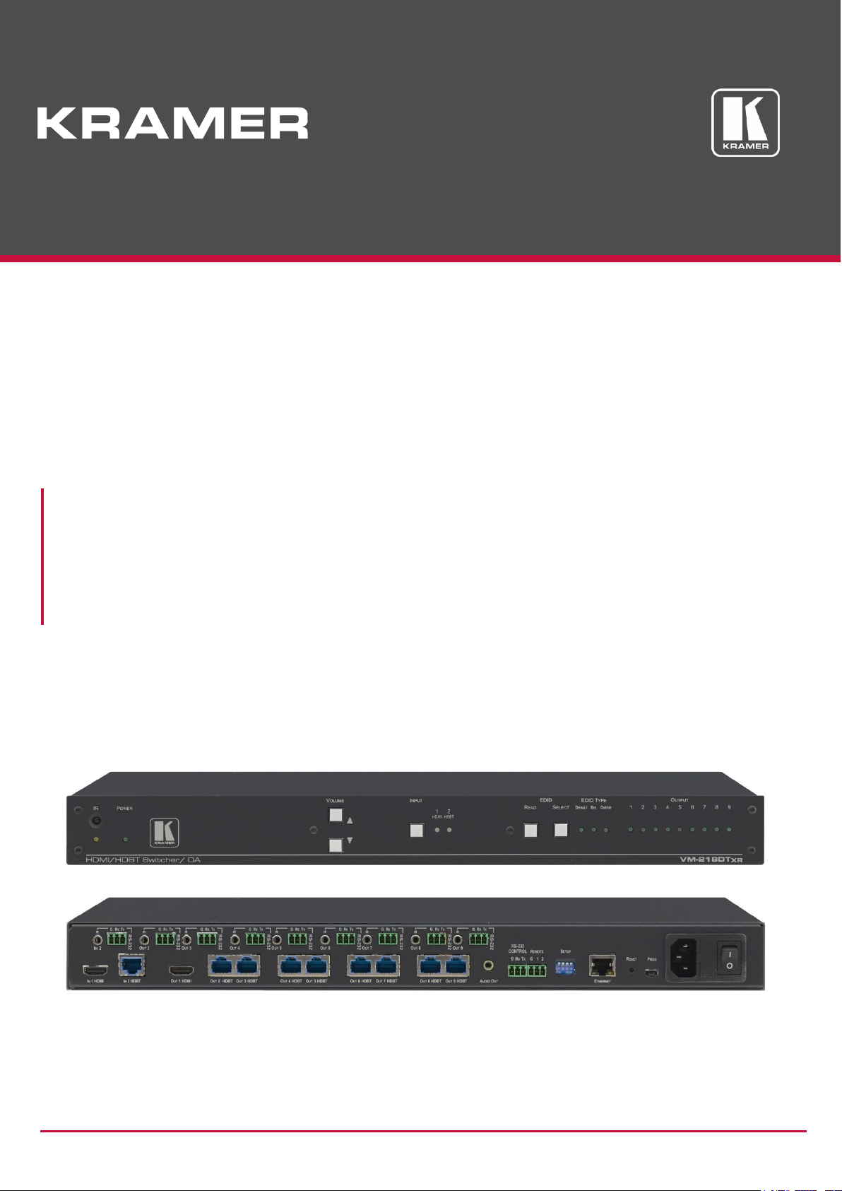
VM-218DTxr, VM-218DT
HDMI/HDBT Switcher DA
Page 2

Kramer Electronics Ltd.
VM-218DTxr, VM-218DT – Contents
i
Contents
Introduction 1
Getting Started 1
Overview 2
Typical Applications 4
Controlling your VM-218DTxr 4
Defining VM-218DTxr HDMI/HDBT Switcher DA 5
Installing in a Rack 7
Connecting the HDMI/HDBT Switcher DA 8
Connecting VM-218DTxr 8
Connecting VM-218DT 9
Extending Control Signals 10
Controlling VM-218DTxr via RS-232 CONTROL 12
Wiring the RJ 45 Connectors 12
Setting the DIP-switches 13
Cascading Devices 14
Operating and Controlling the VM-218DTxr 15
Using the Front Panel Buttons 15
Acquiring the EDID 15
Using the Ethernet 16
Using the Embedded Web Pages 20
Browsing VM-218DTxr Web Pages 20
Switching the Inputs and Setting the Output Volume 22
Defining Video and Audio Settings 23
Setting the Output Labels 24
Managing EDID 24
Setting Web Page Access Permission 29
Changing Device Settings 31
Upgrading the Firmware 33
Viewing the About Page 34
Upgrading the Firmware 35
Technical Specifications 36
Default Communication Parameters 37
Default EDID 38
Protocol 3000 40
Understanding Protocol 3000 40
Protocol 3000 Commands 41
Result and Error Codes 47
Page 3

Kramer Electronics Ltd.
VM-218DTxr, VM-218DT – Introduction
1
Introduction
Welcome to Kramer Electronics! Since 1981, Kramer Electronics has been providing a world
of unique, creative, and affordable solutions to the vast range of problems that confront the
video, audio, presentation, and broadcasting professional on a daily basis. In recent years, we
have redesigned and upgraded most of our line, making the best even better!
Getting Started
We recommend that you:
• Unpack the equipment carefully and save the original box and packaging materials for
possible future shipment.
• Review the contents of this user manual.
Go to www.kramerav.com/downloads/VM-218DTxr to check for up-to-date user manuals,
application programs, and to check if firmware upgrades are available (where appropriate).
Achieving the Best Performance
• Use only good quality connection cables (we recommend Kramer high-performance,
high-resolution cables) to avoid interference, deterioration in signal quality due to poor
matching, and elevated noise levels (often associated with low quality cables).
• Do not secure the cables in tight bundles or roll the slack into tight coils.
• Avoid interference from neighboring electrical appliances that may adversely influence
signal quality.
• Position your Kramer VM-218DTxr / VM-218DT away from moisture, excessive sunlight
and dust.
This equipment is to be used only inside a building. It may only be connected to other
equipment that is installed inside a building.
Safety Instructions
Caution:
• This equipment is to be used only inside a building. It may only be connected to other
equipment that is installed inside a building.
• For products with relay terminals and GPI\O ports, please refer to the permitted rating
for an external connection, located next to the terminal or in the User Manual.
• There are no operator serviceable parts inside the unit.
Page 4
Kramer Electronics Ltd.
VM-218DTxr, VM-218DT – Introduction
2
Warning:
• Use only the power cord that is supplied with the unit.
• Disconnect the power and unplug the unit from the wall before installing.
• Do not open the unit. High voltages can cause electrical shock! Servicing by qualified
personnel only.
• To ensure continuous risk protection, replace fuses only according to the rating
specified on the product label which located on the bottom of the unit.
Recycling Kramer Products
The Waste Electrical and Electronic Equipment (WEEE) Directive 2002/96/EC aims to reduce
the amount of WEEE sent for disposal to landfill or incineration by requiring it to be collected
and recycled. To comply with the WEEE Directive, Kramer Electronics has made
arrangements with the European Advanced Recycling Network (EARN) and will cover any
costs of treatment, recycling and recovery of waste Kramer Electronics branded equipment on
arrival at the EARN facility. For details of Kramer’s recycling arrangements in your particular
country go to our recycling pages at www.kramerav.com/support/recycling.
Overview
The devices described in this user manual are generally referred to as VM-218DTxr or
HDMI/HDBT Switcher DA. A device is named specifically only when a device-specific
feature is described.
The differences between VM-218DTxr and VM-218DT are summarized in the following table:
Product
Extension
Resolution
Reach
VM-218DTxr
HDMI™, RS-232,
IR, Ethernet
4K @60Hz (4:2:0)
Up to 100m (330ft)
1080p @60Hz 36bpp
Up to 130m (430ft)
1080p @60Hz 24bpp
Up to 180m (590ft)
VM-218DT
HDMI, RS-232, IR
4K @60Hz (4:2:0)
Up to 40m (130ft)
1080p @60Hz 36bpp
Up to 70m (230ft)
Congratulations on purchasing your Kramer VM-218DTxr HDMI/HDBT Switcher DA.
VM-218DTxr is a high-quality, extended-reach 4K@60Hz (4:2:0) HDBaseT (HDBT) distributor
that takes either an HDMI or an extended-reach HDBaseT input (selectable), equalizes and
reclocks the signal and distributes it to eight identical extended-reach HDBaseT outputs, each
with its own Ethernet, RS-232 and IR control signals. The unit also includes a loop HDMI
output along with audio de-embedding (extraction) to analog stereo port. As an integrated
extender distributor, VM-218DTxr re-extends and distributes native extended-reach HDBaseT
signals with up to 4K video resolution.
VM-218DT distributes the selected input signal (HDMI or long-reach HDBaseT) to the eight
long-reach HDBaseT outputs together with RS-232 and IR control signals.
VM-218DTxr provides exceptional quality, advanced and user-friendly operation, and flexible
control.
Page 5

Kramer Electronics Ltd.
VM-218DTxr, VM-218DT – Introduction
3
Exceptional Quality
• High Performance Extender Distributor – High-quality professional 1:8 distribution of
native extended-reach HDBaseT signals, for deploying mid-way between an AV source
and multiple remote displays and gaining extra extended-reach extension. It is coupled
with both sides, input and output, extension of a maximum 4K@60Hz (4:2:0) 24bpp
video resolution signal to maximum 100m (330ft) extended-reach over CAT copper
cable, and even further reach for lower HD video resolution. The extender distributor is
standard and capable of being connected to any market-available HDBaseT compliant
extending product.
• I-EDIDPro™ Kramer Intelligent EDID Processing™ – An intelligent EDID handling,
processing and pass-through algorithm that ensures Plug and Play operation for HDMI
source and display systems.
• Audio De-embedding (Extraction) – The transmitted digital audio signal is converted to
an analog signal and de-embedded to stereo unbalanced analog audio output. This
enables user-selectable de-embedding of input digital audio to play at local hi-quality
speakers separate from a remote receiver-connected AV sink device, such as a TV
display or audio speakers, to provide higher quality audio playback.
Advanced and User-friendly Operation
• HDMI Signal Extension – HDMI 2.0 and HDCP 1.4 compliant signal, supporting deep
color, x.v.Color™, lip sync, 7.1 PCM, Dolby TrueHD, DTS-HD, 2K, 4K, and 3D. EDID
signals are passed through from the source to the display.
• Bidirectional RS-232 Extension – Serial interface data flows in both directions, on each
extension line, enabling data transmission and control of devices.
• Bidirectional Infrared Extension – IR interface data flows in both directions, on each
extension line, enabling remote control of peripheral devices located at either end of the
extended line.
• For VM-218DTxr only, Ethernet Extension – Ethernet interface data flows in both
directions on each extension line, enabling extension of up to 100Mbps Ethernet
connectivity for LAN communication and control of devices.
• Cost-effective Maintenance – Status LED indicators for HDMI and HDBT ports to
facilitate easy local maintenance and troubleshooting.
• Remote IP device management via built-in web pages or RS-232 control connection.
• Simple System Management – Remote system management support to enable quick
and efficient remote system and device life-cycle management.
• Easy operation and control using front panel buttons, or remotely via the Embedded web
pages.
• Local and remote firmware upgrade via mini-USB, control RS-232 or Ethernet
connection and the K-Upload tool to ensure long field-proven deployment.
Page 6

Kramer Electronics Ltd.
VM-218DTxr, VM-218DT – Introduction
4
Flexible Connectivity
• Selectable Inputs – HDMI or HDBT inputs, selectable via front panel buttons, Web UI or
remote system management.
• HDBT Outputs – one HDMI output (loop) and Eight HDBT outputs.
• Field-upgradable Scalability – Multiply your outputs by connecting an additional unit to
the HDMI loop output even while the device is active and operating. The original highquality signal is duplicated at the same quality and simultaneously routed to the
cascaded DA and to all the, transforming your 2x8 unit into a 2x16 switchable DA.
• Flexible control extension – Bidirectional IR, RS-232 or Ethernet (for VM-218DTxr) for
HDBT input and each of the HDBT outputs for control extension.
• Easy Installation – Twisted-pair cables for HDBaseT signals wiring. Rack mountable
enclosure for mounting in a 1U rack space with included rack ears and universal 100–
240V AC power connection.
Typical Applications
VM-218DTxr is ideal for the following typical applications:
• Presentation and multimedia applications.
• Signal distribution to multiple displays spread within large spaces.
• Digital signage.
• Rental and staging.
Controlling your VM-218DTxr
Control your VM-218DTxr directly via the front panel push buttons, or:
• By RS-232 serial commands transmitted by a touch screen system, PC, or other serial
controller.
• Remotely, from the infrared remote-control transmitter.
• Via the Ethernet using built-in user-friendly web pages.
• Via Kramer Network management system.
Page 7
Kramer Electronics Ltd.
VM-218DTxr, VM-218DT – Defining VM-218DTxr HDMI/HDBT Switcher DA
5
Defining VM-218DTxr HDMI/HDBT Switcher DA
VM-218DTxr and VM-218DT appear identical.
This section defines VM-218DTxr.
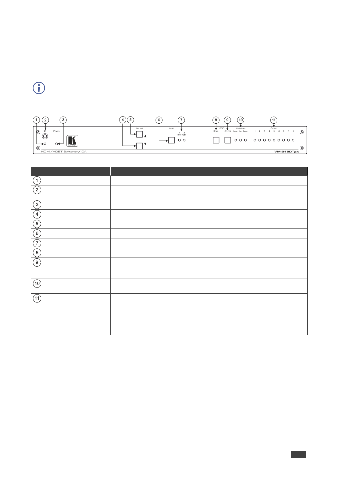
Figure 1: VM-218DTxr HDMI/HDBT Switcher DA Front Panel
#
Feature
Function
IR LED
Lights orange when the unit accepts IR remote commands.
IR Sensor
Use to control a peripheral device connected to OUT 2 HDBT with that
device’s remote controller.
POWER LED
Lights when the unit is powered.
VOLUME ()
Press to decrease the volume of the analog audio output.
VOLUME ()
Press to increase the volume of the analog audio output.
INPUT Selector Button
Press to select input 1 HDMI or input 2 HDBT.
INPUT LEDs
Lights green to indicate the selected input: 1 HDMI or 2 HDBT.
EDID READ Button
Press to read the selected EDID and write it to both inputs.
EDID SELECT Button
Press to cycle through the sources from which to read the EDID: Default,
External, or Output. When Output is selected, cycles through outputs 1 to 9.
The relevant EDID TYPE and OUTPUT LEDs light green.
EDID TYPE LEDs
Lights green to indicate the selected EDID type: DEFAULT, EXT. (external)
or OUTPUT.
OUTPUT LEDs (1 to 9)
In normal operation mode: lights green when an acceptor is connected to the
output.
In EDID mode: when EDID TYPE OUTPUT LED lights green, press the
EDID SELECT button briefly to cycle through output 1 to 9 to select the
output from which to read EDID. The relevant LED lights during EDID setup
and remains lit after completing the EDID setup.
Page 8

Kramer Electronics Ltd.
VM-218DTxr, VM-218DT – Defining VM-218DTxr HDMI/HDBT Switcher DA
6
Figure 2: VM-218DTxr HDMI/HDBT Switcher DA Rear Panel
#
Feature
Function
IN 2 IR on a 3.5 Mini Jack
Connect to an IR emitter/sensor cable for IR link extension via IN 2
HDBT.
IN 2 RS-232 (G, Rx, Tx)
Terminal Block Connector
Connect to a serial controller for RS-232 link extension via IN 2 HDBT.
IN 1 HDMI Connector
Connect to an HDMI source.
IN 2 HDBT on RJ-45
Connectors
Connect to an HDBT transmitter (for example: TP-780Txr for
VM-218DTxr and TP-580T for VM-218DT).
IR on 3.5 Mini Jacks (for
OUT 2 to 9)
Connect to remote IR emitter/sensor cables to IR control the devices that
are connected to the HDBT acceptors.
RS-232 OUT (G, Rx, Tx)
Terminal Block Connectors
(2 to 9)
Connect to serially control the devices connected to the HDBT acceptors.
OUT 1 HDMI Connector
Connect to the HDMI input of an additional DA or connect to a local
monitor.
OUT HDBT RJ-45
Connectors (2 to 9)
Connect to HDBT receivers (for example: TP-780Rxr for VM-218DTxr
and TP-580R for VM-218DT).
AUDIO OUT 3.5mm Mini
Jack
Connect to an analog audio acceptor.
RS-232 CONTROL 3-pin
Terminal Block
Connect to the serial controller to control the VM-218DTxr.
REMOTE 3-pin Terminal
Block
For future use.
SETUP DIP-switches
Use to set the device behavior.
ETHERNET RJ-45
Connector
Connect to LAN for Ethernet extension via IN and OUT HDBT ports and
remote IP control of the VM-218DTxr.
RESET Button
Press and hold while powering on the device to reset to factory default
parameters.
PROG Mini USB Connector
Connect to a PC to perform firmware upgrades.
Mains Power Connector,
Fuse and Switch
Connect to the mains supply.
Page 9
Kramer Electronics Ltd.
VM-218DTxr, VM-218DT – Installing in a Rack
7
Installing in a Rack
This section provides instructions for rack mounting VM-218DTxr. Before installing in a rack,
verify that the environment is within the recommended range:
• Operation temperature – 0 to 40C (32 to 104F).
• Storage temperature – -40 to +70C (-40 to +158F).
• Humidity – 10% to 90%, RHL non-condensing.
When installing on a 19" rack, avoid hazards by taking care that:
• It is located within recommended environmental conditions. Operating ambient
temperature of a closed or multi-unit rack assembly may exceed ambient room
temperature.
• Once rack mounted, there is enough air flow around VM-218DTxr.
• VM-218DTxr is placed upright in the correct horizontal position.
• You do not overload the circuit(s). When connecting VM-218DTxr to the supply
circuit, overloading the circuits may have a detrimental effect on overcurrent
protection and supply wiring. Refer to the appropriate nameplate ratings for
information. For example, for fuse replacement, see the value printed on the
product label.
• VM-218DTxr is earthed (grounded) and connected only to an electricity socket with
grounding. Pay particular attention when electricity is supplied indirectly (for
example, when the power cord is not plugged directly into the wall socket but to an
extension cable or power strip). Use only the supplied power cord.
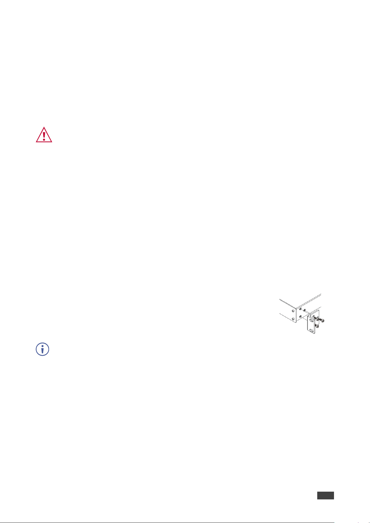
To rack mount the machine, attach both ear brackets (by removing the
screws from each side of the machine and replacing those screws
through the `ear brackets) or place the machine on a table.
• Detachable rack ears can be removed for desktop use.
• Always mount VM-218DTxr in the rack before connecting any cables or power.
Page 10
Kramer Electronics Ltd.
VM-218DTxr, VM-218DT – Connecting the HDMI/HDBT Switcher DA
8
Connecting the HDMI/HDBT Switcher DA
Although both the VM-218DTxr and VM-218DT appear identical, the VM-218DTxr also
extends Ethernet signals, therefore the connecting procedures in this section are described
separately for each device.
Always switch off the power to each device before connecting it to your VM-218DTxr. After
connecting your VM-218DTxr, connect its power and then switch on the power to each
device.
Connecting VM-218DTxr
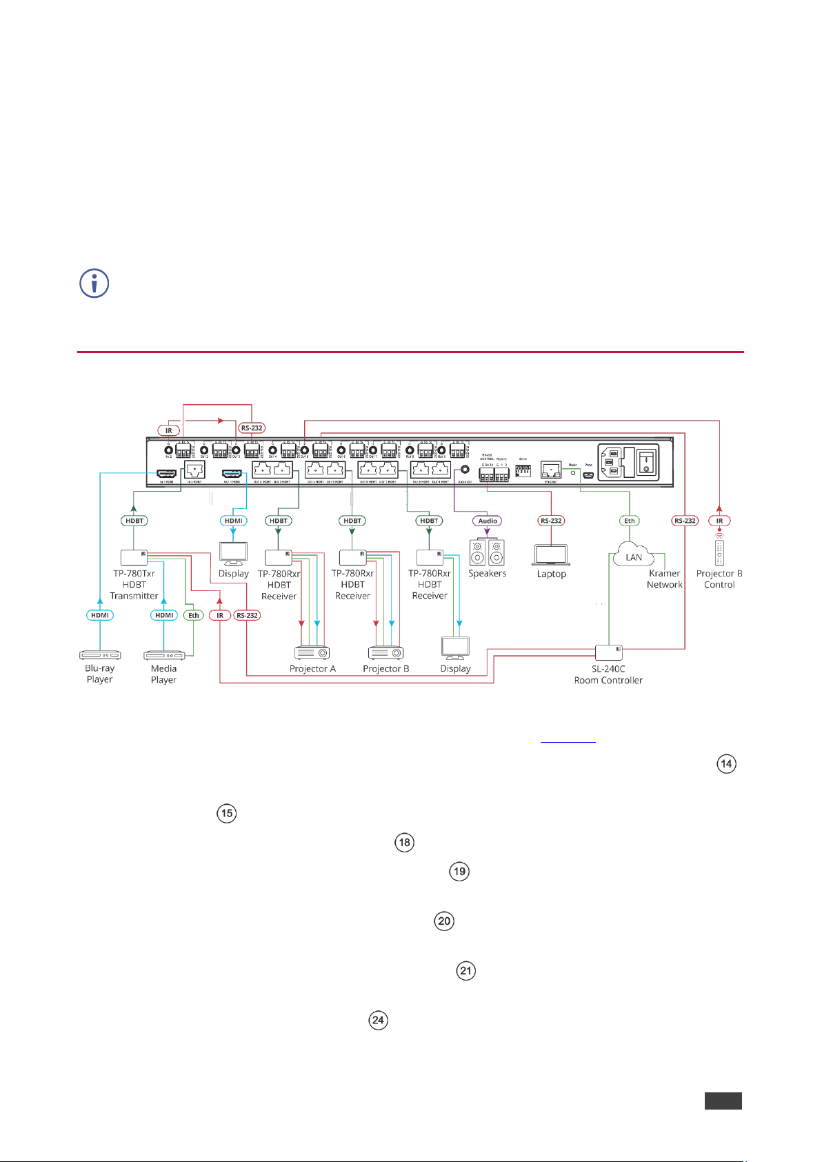
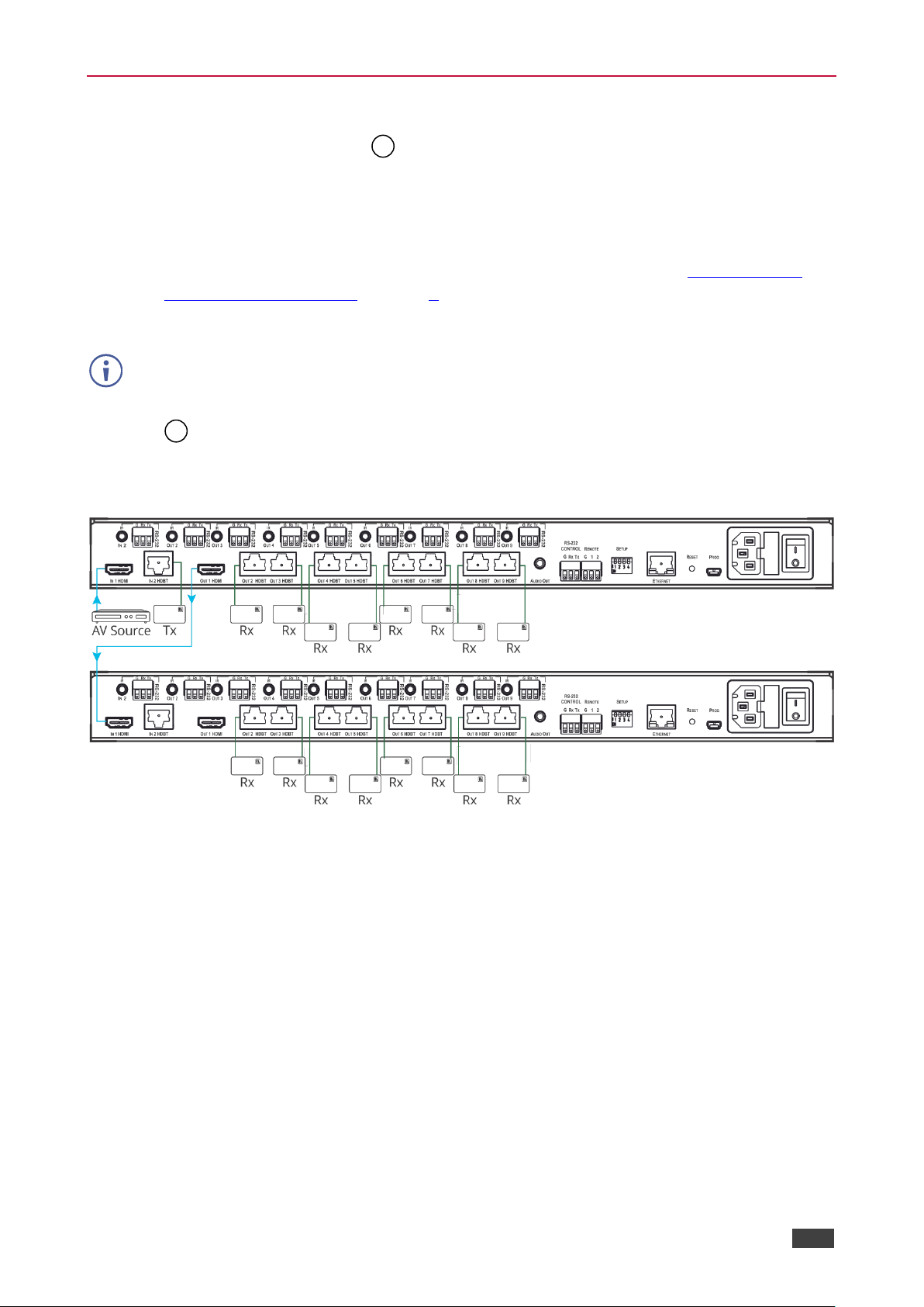
Figure 3: Connecting to VM-218DTxr
To connect the VM-218DTxr as illustrated in the example in Figure 3:
1. Connect an HDMI source (for example, a Blu-ray player) to the IN 1 HDMI connector .
2. Connect an HDBT transmitter (for example, Kramer TP-780Txr) to the IN 2 HDBT RJ-45
connector .
3. Connect the OUT 1 HDMI connector to an HDMI acceptor (for example, a display).
4. Connect the 8 OUT HDBT RJ-45 connectors (2 to 9) to up to 8 HDBT receivers (for
example, Kramer TP-780Rxr receivers).
5. Connect the AUDIO OUT 3.5mm mini jack to an analog audio acceptor (for example,
Kramer Tavor 6-O speakers).
6. Connect the RS-232 terminal block connector to a serial control device (for example,
a laptop) to control VM-218DTxr.
7. Connect the Ethernet RJ-45 port to the Ethernet LAN to control the VM-218DTxr and
LAN-connected peripheral devices, either local LAN or through input HDBT extended
Page 11
Kramer Electronics Ltd.
VM-218DTxr, VM-218DT – Connecting the HDMI/HDBT Switcher DA
9
Ethernet, via IP control device (for example, a laptop) and/or an IP room controller (for
example, Kramer SL-240C).
8. Connect the power adapter to the VM-218DTxr and to the mains electricity (not
shown in Figure 3).
9. Connect signal extensions (see Extending Control Signals on page 10).
The USB connector and power cord are not shown in Figure 3.
Connecting VM-218DT
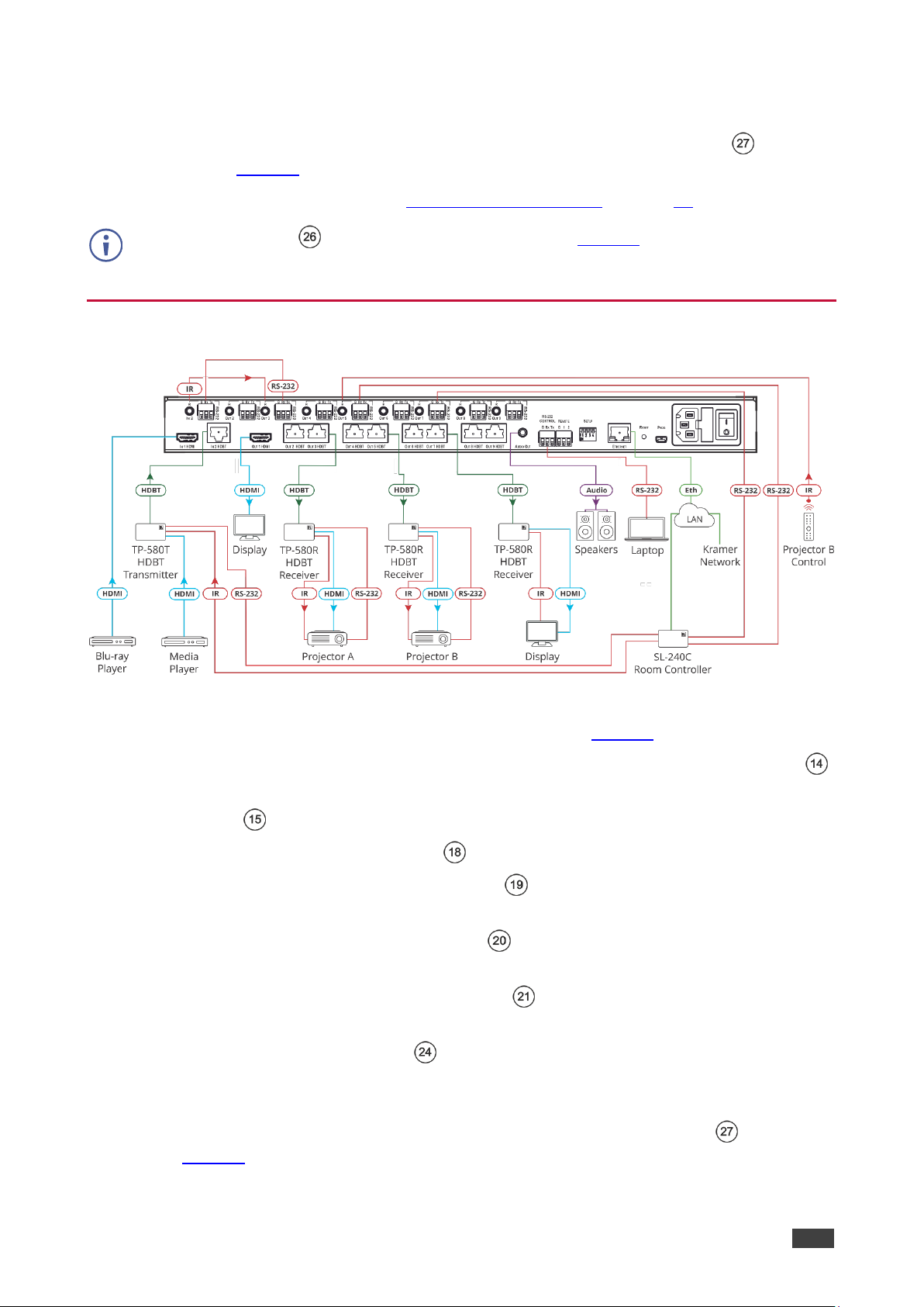
Figure 4: Connecting to VM-218DT
To connect the VM-218DT as illustrated in the example in Figure 4:
1. Connect an HDMI source (for example, a Blu-ray player) to the IN 1 HDMI connector .
2. Connect an HDBT transmitter (for example, Kramer TP-580T) to the IN 2 HDBT RJ-45
connector .
3. Connect the OUT 1 HDMI connector to an HDMI acceptor (for example, a display).
4. Connect the 8 OUT HDBT RJ-45 connectors (2 to 9) to up to 8 HDBT receivers (for
example, Kramer TP-580R receivers).
5. Connect the AUDIO OUT 3.5mm mini jack to an analog audio acceptor (for example,
Kramer Tavor 6-O speakers).
6. Connect the RS-232 terminal block connector to a serial control device (for example,
a laptop) to control the VM-218DT.
7. Connect the Ethernet RJ-45 port to the Ethernet LAN to control the VM-218DT and
its peripheral devices and/or to a room controller (for example, Kramer
SL-240C).
8. Connect the power adapter to the VM-218DT and to the mains electricity (not shown
in Figure 4).
Page 12

Kramer Electronics Ltd.
VM-218DTxr, VM-218DT – Connecting the HDMI/HDBT Switcher DA
10
9. Connect signal extensions. See:
▪ IR Extension on page 10.
▪ RS-232 Extension on page 11.
The USB connector and power cord are not shown in Figure 4.
Extending Control Signals
VM-218DTxr can extend IR, RS-232 and Ethernet control signals to peripheral devices that
are connected to the relevant ports on the transmitter and receivers that are connected to the
VM-218DTxr.
VM-218DT can extend IR and RS-232 control signals in the same way.
The following procedures provide examples for extending signals.
You can extend only one type of signal (RS-232, IR or Ethernet-for VM-218DTxr only) to
control a peripheral device.
Figure 3 (for VM-218DTxr) and Figure 4 (for VM-218DT) show several types of signal
extensions for each HDBT device, for illustrating device capabilities only.
IR Extension
Use the IR 3.5mm mini jacks for the HDBT input and outputs to extend IR control
signals between any set of IR ports on the HDBT transmitter and receivers.
To extend an IR signal, for example, from VM-218DTxr to Projector B:
1. Connect an IR sensor cable to the OUT 5 IR 3.5mm mini jack.
2. Connect an IR emitter cable between the TP-780Rxr receiver (that is connected to
OUT 5) and Projector B.
3. Point the Projector B IR remote-control transmitter to the IR sensor to control Projector B
via the TP-580Rxr receiver that is connected to HDBT OUT 5.
In the same way you can control other peripheral devices connected to the HDBT-connected
transmitter and/or receivers.
To extend an IR signal, for example, from a remote room controller to Projector A:
1. Connect an IR cable between a room controller (for example, Kramer SL-240C) and the
IR port of the IN 2 HDBT-connected on the TP-780Txr transmitter.
2. Connect an IR cable between the IN 2 IR 3.5mm mini jack and the OUT 3 3.5mm mini
jack.
3. Connect an IR emitter cable between the IR port of the TP-780Rxr receiver that is
connected to OUT 3 and the IR port on Projector A.
4. Send an IR signal from the room controller to Projector A via the IN 2 TP-780Txr
transmitter and the OUT 3 TP-780Rxr receiver.
Page 13

Kramer Electronics Ltd.
VM-218DTxr, VM-218DT – Connecting the HDMI/HDBT Switcher DA
11
In the same way you can pass IR signals to control other connected peripheral devices using
the IR ports of the VM-218DTxr, HDBT transmitter and HDBT receivers.
RS-232 Extension
Use the RS-232 3-pin terminal block connectors for the HDBT input and outputs to
extend RS-232 control signals between any set of RS-232 ports on the HDBT transmitter and
receivers.
To extend an RS-232 signal, for example, from VM-218DTxr to Projector B:
1. Connect OUT 5 RS-232 3-pin terminal block connector to a room controller (for example,
the Kramer SL-240C room controller.
2. Connect the RS-232 port on the TP-780Rxr receiver (that is connected to HDBT OUT 5)
to Projector B.
3. Send an RS-232 command from the room controller to Projector B.
In the same way you can control other peripheral devices that are connected to the
transmitter and/or receivers.
To extend an RS-232 signal, for example, from a remote room controller to Projector A:
1. Connect an RS-232 cable between a room controller (for example, Kramer SL-240C)
and the RS-232 port on the TP-780Txr transmitter that is connected to HDBT IN 2.
2. Connect an RS-232 cable between the IN 2 RS-232 3-pin terminal block connector and
the OUT 3 RS-232 3-pin terminal block connector.
3. Connect an RS-232 cable between the TP-780Rxr (that is connected to OUT 3 HDBT)
RS-232 port and Projector A.
4. Send an RS-232 command from the room controller to Projector A on the TP-780Rxr via
the HDBT IN 1 port.
In the same way you can send RS-232 commands to control other peripheral devices
connected to the transmitter/receivers.
In the same way you can send RS-232 signals and commands to control other peripheral
devices connected between the RS-232 ports of the VM-218DTxr, HDBT transmitter and
HDBT receivers.
Ethernet Extension (VM-218DTxr only)
Use the ETHERNET RJ-45 port input and outputs to extend Ethernet signals via
control devices and/or control software to and from the HDBT transmitter/receivers.
To send a command from a room controller, for example, to the display:
1. Connect the ETHERNET RJ-45 port to the Ethernet.
2. Connect the ETH port of a room controller (for example, the Kramer SL-240C room
controller) to the Ethernet.
Page 14
Kramer Electronics Ltd.
VM-218DTxr, VM-218DT – Connecting the HDMI/HDBT Switcher DA
12
3. Send an RS-232 command from the room controller to the display on the TP-780Rxr via
the HDBT OUT 7 port.
In the same way you can control other peripheral devices connected to the
transmitter/receivers.
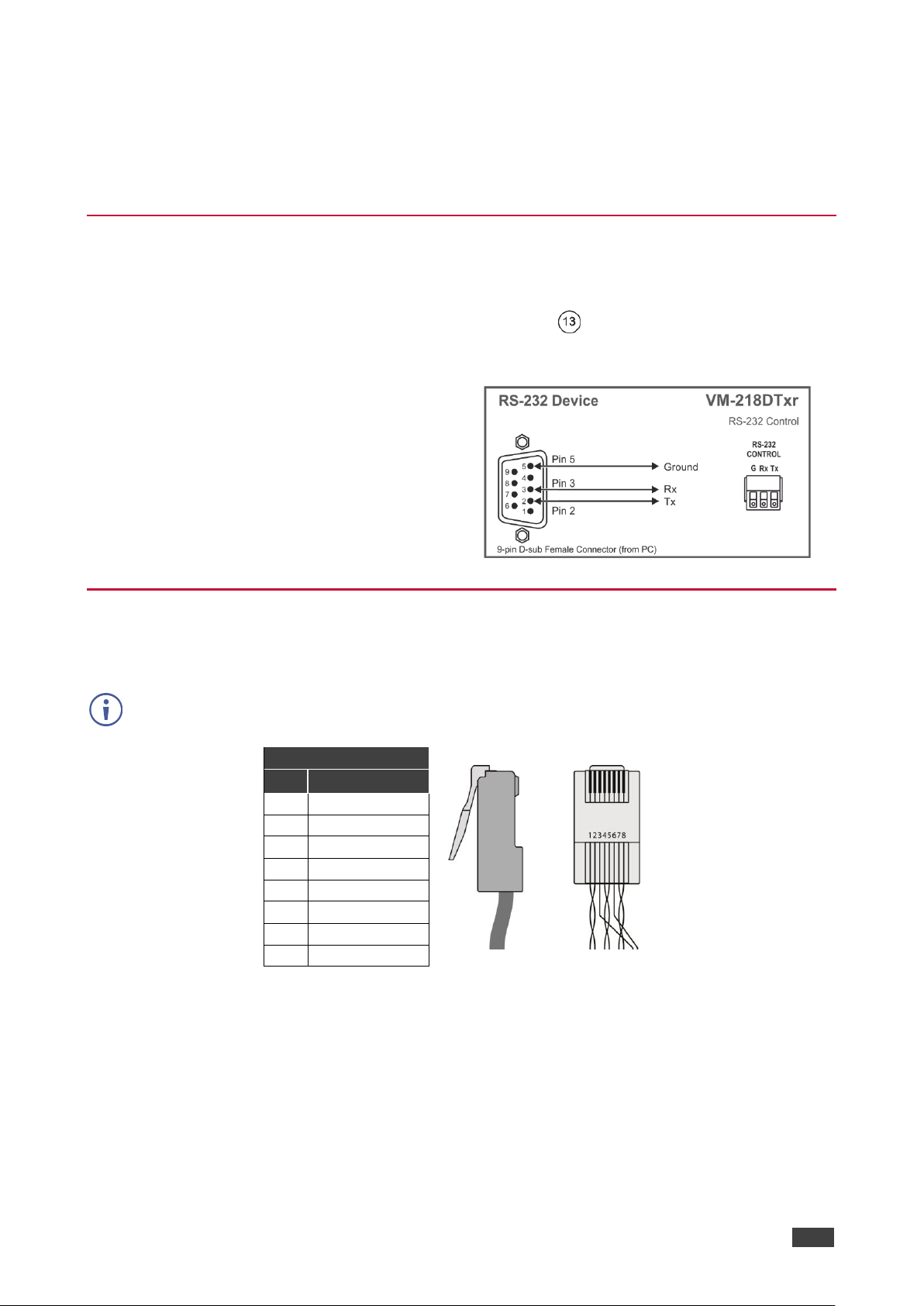
Controlling VM-218DTxr via RS-232 CONTROL
VM-218DTxr features an RS-232 CONTROL 3-pin terminal block connector allowing the
RS-232 to control the VM-218DTxr. To do so, connect the VM-218DTxr to a controller (for
example a PC) via the RS-232 CONTROL terminal block on the rear panel as follows:
• Pin 2 to the TX pin on the VM-218DTxr
RS-232 CONTROL terminal block.
• Pin 3 to the RX pin on the VM-218DTxr
RS-232 CONTROL terminal block.
• Pin 5 to the G pin on the VM-218DTxr
RS-232 CONTROL terminal block.
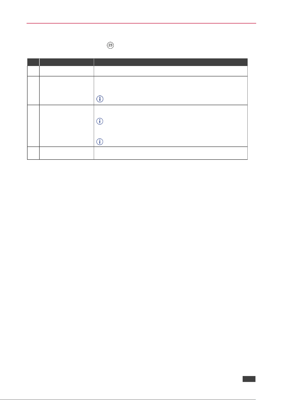
Wiring the RJ 45 Connectors
This section defines the HDBT pinout, using a straight pin-to-pin cable with RJ 45 connectors.
For HDBT cables, it is recommended that the cable ground shielding be connected/soldered
to the connector shield.
EIA /TIA 568B
PIN
Wire Color
1
Orange / White
2
Orange
3
Green / White
4
Blue
5
Blue / White
6
Green
7
Brown / White
8
Brown
Page 15
Kramer Electronics Ltd.
VM-218DTxr, VM-218DT – Connecting the HDMI/HDBT Switcher DA
13
Setting the DIP-switches
Changes to the DIP-switches only take effect following power-up. After changing a switch,
reboot the device. All DIP-switches are set to Off (up) by default.
#
Feature
Dip-switch Settings
1
Reserved
2
Range mode
Off (up) – Normal range (default).
On (down) – HDBaseT Ultra-long range (provides increased range at
a reduced bandwidth).
Note that range mode affects the HDBT input only.
3
Audio de-embedding
Off (up) – Enable 2-channel uncompressed audio de-embedding to
the analog audio output port (default).
Note that compressed audio pass-through is disabled.
On (down) – Disable audio de-embedding and enable pass-through of
all audio formats.
Note that the analog audio output port is muted.
4
Force RGB
Off (up) – Normal mode (default).
On (down) – Force RGB mode.
Page 16
Kramer Electronics Ltd.
VM-218DTxr, VM-218DT – Connecting the HDMI/HDBT Switcher DA
14
Cascading Devices
Use the OUT 1 HDMI connecter on VM-218DTxr to connect a local monitor or to
distribute the signal to an additional receiver, thus creating a 2x16 DA system as described in
the following example.
To cascade VM-218DTxr:
1. Connect the inputs and outputs to the primary device as described in Connecting the
HDMI/HDBT Switcher DA on page 8, except for the OUT 1 HDMI connector.
2. On the cascaded DA device, connect the receivers as required.
Connect the power to the receivers only after connecting them to the cascaded device.
3. Connect the OUT 1 HDMI connector on the primary device to the IN 1 HDMI connector
on the cascaded DA device.
4. After powering the cascaded device, make sure that the HDMI input is selected on the
cascaded device.
Figure 5: Cascading DAs
18
14
Page 17

Kramer Electronics Ltd.
VM-218DTxr, VM-218DT – Operating and Controlling the VM-218DTxr
15
Operating and Controlling the VM-218DTxr
Control VM-218DTxr in the following ways:
• Using the Front Panel Buttons on page 15.
• Acquiring the EDID on page 15.
• Using the Ethernet on page 16.
Using the Front Panel Buttons
Use the VM-218DTxr front panel buttons:
• Press VOLUME and to set the analog audio output volume.
• Press INPUT to select the required input (indicated by HDMI and HDBT LEDs ).
• Press EDID SELECT and EDID READ to acquire the EDID (see Acquiring the
EDID on page 15).
Acquiring the EDID
Initially, each input on the VM-218DTxr has a factory default EDID loaded (see Default EDID
on page 38). This lets you connect the power to VM-218DTxr while an active source is
connected before having to connect one of the acceptors. VM-218DTxr reads the EDID,
which is stored in the non-volatile memory and uses it for the active connected sources.
In the same way, the acquired EDID from a connected output or an external source is stored
in the non-volatile memory.
You can acquire the EDID from any of the following sources:
• DEFAULT: The factory default EDID.
• OUTPUT: Active acceptors that are connected to OUT 1 HDMI or OUT (2 to 9) HDBT.
• EXTERNAL: A custom EDID (acquired via EDID Designer software, by connecting a PC
to VM-218DTxrt via RS-232 or USB ports).
You can acquire the EDID using:
• The front panel buttons (see Acquiring EDID via the Front Panel Buttons on page 16)
• The embedded web pages (see Managing EDID on page 24)
Page 18

Kramer Electronics Ltd.
VM-218DTxr, VM-218DT – Operating and Controlling the VM-218DTxr
16
• EDID Designer software.
VM-218DTxr Supports EDID Designer (via the mini USB port) that can be
loaded from our Web site: Kramer EDID Designer.
To use the mini USB port, you need to download and the Kramer USB driver
from our Web site at: www.kramerav.com/support/product_downloads.asp and
install it.
Acquiring EDID via the Front Panel Buttons
The following procedure is usually done only once, when the device is being set up.
To acquire the EDID:
1. Press EDID SELECT repeatedly until the required EDID source is selected, (either
DEFAULT, EXT, or OUTPUT LED lights ).
When selecting OUTPUT, keep pressing repeatedly to select the desired output.
The relevant LED lights green.
2. Press EDID READ .
EDID READ flashes once and the EDID is copied to the currently selected input.
EDID READ flashing 3 times indicates that the EDID was not read.
The device reverts to the last stored EDID type, as indicated by the relevant EDID
TYPE LEDs.
If the EDID READ button is not pressed for five seconds, the procedure is terminated, the
device does not store a new EDID and the OUTPUT 1 to 9 LEDs revert to normal operation.
Forcing the RGB Mode
Normally (the default state), when acquiring EDID, the device supports any color space that is
defined in the acquired EDID parameters. In case of a color space problem, enabling Force
RGB mode may improve the colors of the image on the display.
Force RGB mode is enabled via the DIP-switches on the rear panel (see Setting the DIP-
switches on page 13).
Using the Ethernet
You can connect to the VM-218DTxr via Ethernet using either of the following methods:
• Locally, directly to the laptop using a crossover cable (see Connecting the Ethernet Port
Directly to a Laptop on page 17).
• Remotely over IP LAN, via a network hub, switch, or router, using a straight-through
cable (see Connecting the Ethernet Port via IP LAN on page 19).
Note: If you want to connect via a router and your IT system is based on IPv6, speak to your
IT department for specific installation instructions.
Page 19

Kramer Electronics Ltd.
VM-218DTxr, VM-218DT – Operating and Controlling the VM-218DTxr
17
Connecting the Ethernet Port Directly to a Laptop
You can connect the Ethernet port of the VM-218DTxr directly to the Ethernet port on your
PC using a crossover cable with RJ-45 connectors.
This type of connection is recommended for identifying the VM-218DTxr
with the factory configured default IP address.
After connecting the VM-218DTxr to the Ethernet port, configure your PC as follows:
1. Click Start > Control Panel > Network and Sharing Center.
2. Click Change Adapter Settings.
3. Highlight the network adapter you want to use to connect to the device and click Change
settings of this connection.
The Local Area Connection Properties window for the selected network adapter appears
as shown in Figure 6.
Figure 6: Local Area Connection Properties Window
4. Highlight either Internet Protocol Version 6 (TCP/IPv6) or Internet Protocol Version 4
(TCP/IPv4) depending on the requirements of your IT system.
5. Click Properties.
The Internet Protocol Properties window relevant to your IT system appears as shown in
Figure 7 or Figure 8.
Page 20

Kramer Electronics Ltd.
VM-218DTxr, VM-218DT – Operating and Controlling the VM-218DTxr
18
Figure 7: Internet Protocol Version 4 Properties Window
Figure 8: Internet Protocol Version 6 Properties Window
6. Select Use the following IP Address for static IP addressing and fill in the details as
shown in Figure 9.
For TCP/IPv4 you can use any IP address in the range 192.168.1.1 to 192.168.1.255
(excluding 192.168.1.39) that is provided by your IT department.
Page 21

Kramer Electronics Ltd.
VM-218DTxr, VM-218DT – Operating and Controlling the VM-218DTxr
19
Figure 9: Internet Protocol Properties Window
7. Click OK.
8. Click Close.
Connecting the Ethernet Port via IP LAN
You can connect the Ethernet port of the VM-218DTxr, via IP LAN, to the Ethernet port on a
network hub or using a straight-through cable with RJ-45 connectors.
Configuring the Ethernet Port
You can set the Ethernet parameters via the embedded Web pages.
Page 22

Kramer Electronics Ltd.
VM-218DTxr, VM-218DT – Using the Embedded Web Pages
20
Using the Embedded Web Pages
The VM-218DTxr can be operated remotely using the embedded web pages. The web pages
are accessed using a web browser and an Ethernet connection.
Before attempting to connect:
• Perform the procedures in Using the Ethernet on page 16.
• Ensure that your browser is supported.
The following operating systems and Web browsers are supported:
OS
Version
Windows 7
IE
Firefox
Chrome
Safari
Windows 10
IE
Edge
Firefox
Chrome
Mac
Safari
iOS
Safari
Browsing VM-218DTxr Web Pages
To browse the VM-218DTxr Web pages:
1. Open your Internet browser.
2. Type the IP number of the device in the Address bar of your browser. For example, the
default IP number:
The Authentication window appears (if set, security is enabled):
Figure 10: Using the Embedded Web Pages – The Authentication Window
Page 23

Kramer Electronics Ltd.
VM-218DTxr, VM-218DT – Using the Embedded Web Pages
21
3. Enter the User Name and Password (Admin, Admin) and click OK.
The Switching Web page appears (see Figure 11).
The VM-218DTxr Web pages enable performing the following:
• Switching the Inputs and Setting the Output Volume on page 22.
• Defining Video and Audio Settings on page 23.
• Setting the Output Labels on page 24.
• Managing EDID on page 24.
• Setting Web Page Access Permission on page 29.
• Changing Device Settings on page 31.
• Upgrading the Firmware on page 33.
• Viewing the About Page on page 34.
Page 24

Kramer Electronics Ltd.
VM-218DTxr, VM-218DT – Using the Embedded Web Pages
22
Switching the Inputs and Setting the Output Volume
The Switching page enables performing the following functions:
• Switching the Inputs on page 22.
• Setting the Volume on page 22.
Switching the Inputs
To select an input to switch to the outputs:
1. In the Navigation pane, click Switching. The Switching page appears.
Figure 11: Switching Page with Navigation List on the Left
2. Click an input to route it to the outputs.
A green dot on the input button indicates that the input is connected and active.
3. Click to edit the input label name.
Setting the Volume
To set the analog audio volume:
1. In the Navigation pane, click Switching. The Switching page appears.
2. Use the slider to set the Analog Output Volume (0dB, by default).
3. If required, click to mute/unmute the output.
Page 25

Kramer Electronics Ltd.
VM-218DTxr, VM-218DT – Using the Embedded Web Pages
23
Defining Video and Audio Settings
The Video and Audio Settings page enables performing the following functions:
• Setting the Power-Off Delay on page 23.
• Supporting HDCP Mode on page 23.
• Viewing Audio De-Embedding Status on page 24.
Setting the Power-Off Delay
When a signal is lost, you can set the output 5V power off delay time.
When 5V on the output is powered down, it indicates to the display connected to it that no
video signal is present.
To set the power-off delay time:
1. In the Navigation pane, click Video & Audio Settings. The Video & Audio Settings page
appears.
Figure 12: Video & Audio Settings Page
2. Set the delay time (900sec, by default).
3. Click Set.
The delay time is set.
Supporting HDCP Mode
To Enable/disable HDCP for each input:
1. In the Navigation pane, click Video & Audio Settings. The Video & Audio Settings page
appears.
2. Click Enable (default)/Disable per input.
Setting HDCP support to disabled on the HDMI input allows the source to transmit a
non-HDCP signal if required (for example, when working with a Mac computer).
HDCP mode is set per input.
Page 26

Kramer Electronics Ltd.
VM-218DTxr, VM-218DT – Using the Embedded Web Pages
24
Viewing Audio De-Embedding Status
In the Navigation pane, click Video and Audio Settings to view the audio de-embedding
status as set by DIP-switch 3 (see Setting the DIP-switches on page 13).
Setting the Output Labels
Use the Output Settings page to label the different outputs. This can be very helpful (for
example, for supporting the system) since HDBT outputs 2 to 9 that are connected to
receivers can be identified easily on location.
To change an output label name:
1. In the Navigation pane, click Output Settings. The Output Settings page appears.
Figure 13: Output Settings Page
2. Type the new output label and click .
Managing EDID
Use the EDID page to read the EDID from:
▪ Any of the inputs.
▪ Any of the outputs.
▪ The default EDID.
Page 27

Kramer Electronics Ltd.
VM-218DTxr, VM-218DT – Using the Embedded Web Pages
25
You can also load an external custom EDID file from your PC onto the VM-218DTxr.
The selected EDID can be copied to the selected input/s.
View the currently selected EDID source Bytemap by clicking Bytemap on the right
side.
To copy an EDID from an input (or output) to an input:
1. In the Navigation pane, click EDID Management. The EDID Management page appears.
Figure 14: EDID Management Page
Page 28

Kramer Electronics Ltd.
VM-218DTxr, VM-218DT – Using the Embedded Web Pages
26
2. Select the EDID source (for example, one of the inputs).
If you are reading EDID from an output, make sure that that output is connected to an
acceptor.
Figure 15: EDID Management Page – Select an EDID Input (Read From)
Page 29

Kramer Electronics Ltd.
VM-218DTxr, VM-218DT – Using the Embedded Web Pages
27
3. Select the input/s (or all the inputs) to which the EDID is copied.
Figure 16: EDID Management Page – Select the Inputs (Copy To)
Page 30

Kramer Electronics Ltd.
VM-218DTxr, VM-218DT – Using the Embedded Web Pages
28
4. Click COPY.
The Input 2 EDID is copied to the selected inputs.
Figure 17: EDID Management Page – EDID Copied
Once the EDID is copied, a success message appears:
Figure 18: EDID Management Page – EDID Copied Successfully
5. Click OK.
To read the EDID from the default EDID:
1. In the Navigation pane, click EDID Management. The EDID Management page appears.
2. Click Default.
3. Select the input/s (or all the inputs) to which the default EDID is copied.
4. Click Copy and follow the instructions on-screen.
Page 31

Kramer Electronics Ltd.
VM-218DTxr, VM-218DT – Using the Embedded Web Pages
29
To load an external EDID file:
1. In the Navigation pane, click EDID Management. The EDID Management page appears.
2. In the File area, click … to browse for the EDID file location.
3. Open the EDID file.
4. Select the input/s (or all the inputs) to which the EDID is copied.
5. Click Copy and follow the instructions on-screen.
Setting Web Page Access Permission
To define access permission to the web pages in the Navigation pane, click Authentication.
The Authentication page appears.
By default, the Web pages are secured (username and password are both Admin).
Figure 19: Authentication Page
To change the password:
1. In the Navigation pane, click Authentication. The Authentication page appears.
2. Type current password and then type the new password twice.
3. Click Change to store the new password. The following message appears:
Figure 20: Authentication – Reloading Web Page
Page 32

Kramer Electronics Ltd.
VM-218DTxr, VM-218DT – Using the Embedded Web Pages
30
To disable security:
1. In the Navigation pane, click Authentication. The Authentication page appears.
2. Click Disabled.
3. The Confirm window appears.
Figure 21: Authentication – Confirm Window
4. Type the password to disable the authentication.
5. Click OK.
Authentication is disabled:
Figure 22: Authentication – Authentication Disabled
To enable security:
1. In the Navigation pane, click Authentication. The Authentication page appears.
2. Click Enabled.
The following message appears:
Figure 23: [Figure Caption]
3. Click OK.
The page reloads, and authentication is required.
Page 33

Kramer Electronics Ltd.
VM-218DTxr, VM-218DT – Using the Embedded Web Pages
31
Changing Device Settings
Use the Device Settings page to change the device name (click Set) and perform the
following operations:
• Changing the Ethernet Settings on page 31.
• Loading/Saving a Configuration on page 32.
• Factory Reset on page 33.
Changing the Ethernet Settings
To change the Ethernet settings:
1. In the Navigation pane, click Device Settings. The Device Settings page appears:
Figure 24: The Device Settings Page
Page 34

Kramer Electronics Ltd.
VM-218DTxr, VM-218DT – Using the Embedded Web Pages
32
2. Set DHCP ON or OFF (default).
3. If DHCP is OFF, change any of the parameters (IP Address, Netmask and/or Gateway).
4. Click Set.
• After changing the IP Address, or DHCP to ON, reload the Web page with the new IP
address.
• After changing the Subnet mask, turn the VM-218DTxr power off and then on again.
Loading/Saving a Configuration
To Save a configuration file to your PC:
1. In the Navigation pane, click Device Setting. Device Settings page appears.
2. Click Save.
The configuration is saved, and the following message appears:
Figure 25: Device Settings - Saving the Configuration
3. Click click here to save and download the configuration to your PC.
To Load a configuration from your PC:
1. In the Navigation pane, click Device Setting. Device Settings page appears.
2. Click Load and browse for the configuration file.
3. Select the configuration file and click Open. The configuration file is uploaded, and the
following message appears:
Figure 26: Device Settings – Configuration Uploaded
4. Click OK.
Page 35

Kramer Electronics Ltd.
VM-218DTxr, VM-218DT – Using the Embedded Web Pages
33
Factory Reset
To reset the device to its factory default parameters:
1. In the Navigation pane, click Device Settings. The Device Settings page appears.
2. Click Factory reset the following message appears:
Figure 27: Device Settings Page – Factory Reset Message
3. Click OK and wait for the web page to reload following factory reset.
See Default Communication Parameters on page 37 to view other factory reset procedures.
Upgrading the Firmware
To perform firmware upgrade:
1. In the Navigation pane, click Firmware Upgrade. The Firmware Upgrade page appears.
Figure 28: Firmware Upgrade Page – Selecting the New Firmware File
2. Click Update and select the new firmware file from the new firmware folder.
Figure 29: Firmware Upgrade Page – Update Warning Message
Page 36

Kramer Electronics Ltd.
VM-218DTxr, VM-218DT – Using the Embedded Web Pages
34
3. Click OK. Wait for the new firmware update completion:
Figure 30Firmware Upgrade Page – Uploading New Firmware
4. Once complete, the web page reloads.
5. Make sure that the new version appears in the Firmware Upgrade page.
Viewing the About Page
In the Navigation pane, click About to view the VM-218DTxr Web page version and Kramer
Electronics Ltd details.
Figure 31: About Page
Page 37

Kramer Electronics Ltd.
VM-218DTxr, VM-218DT – Upgrading the Firmware
35
Upgrading the Firmware
Upgrade the firmware in any of the following ways:
• Remotely, via the Embedded web pages (see Upgrading the Firmware on page 33).
• Remotely, via Kramer Network (see www.kramerav.com/manual/Kramer Network).
• Locally, via Kramer K-UPLOAD software connecting the device to your PC by PROG
micro USB port , or via the RS-232 (when DIP-switch 6 set to Off (up position)
allowing RS-232 to control/program the device).
The latest version of K-UPLOAD and installation instructions can be downloaded from
our website at: www.kramerav.com/support/product_downloads.asp.
Note that in order to use the micro USB port, you need to install the Kramer
USB driver, available at: www.kramerav.com/support/product_downloads.asp.
Page 38

Kramer Electronics Ltd.
VM-218DTxr, VM-218DT – Technical Specifications
36
Technical Specifications
Inputs
1 HDMI
On a female HDMI connector
1 HDBT
On an RJ-45 connector
Outputs
1 HDMI
On a female HDMI connector
8 HDBT
On RJ-45 connector
1 Unbalanced Stereo Audio
On a 3.5mm mini jack
Ports
1 IR IN
On a 3.5mm mini jack for IR link extension via
IN 2 HDBT
8 IR OUT
On 3.5mm mini jacks for IR link extension via
OUT HDBT (2 to 9)
1 RS-232 IN
On a 3-pin terminal block for serial link
extension via IN 2 HDBT
8 RS-232 OUT
On 3-pin terminal blocks for serial link
extension via OUT HDBT (2 to 9)
1 Mini USB
On a female USB connector for firmware
upgrade
1 RS-232
On a 3-pin terminal block for device control
1 10/100BaseT Ethernet
On an RJ-45 female connector for device
control via LAN and Ethernet link extension
via IN HDBT and OUT HDBT (2 to 9)
Extension Reach
VM-218DTxr
4K @60Hz (4:2:0)
Up to 100m (330ft)
Full HD (1080p @60Hz 36bpp)
Up to 130m (430ft)
HDBaseT Ultra Mode and Full HD
(1080p @60Hz 24bpp)
Up to 180m (590ft)
VM-218DT
4K @60Hz (4:2:0)
Up to 40m (130ft)
Full HD (1080p @60Hz 36bpp)
Up to 70m (230ft)
Compliance
HDBaseT 1.0
Video
Max. Resolution
4K@60Hz (4:2:0) and 4K@30Hz (4:4:4)
Compliance
Supports HDMI 2.0 and HDCP 1.4
RS-232 Extension
Baud Rate
300 to 115,200
Analog Audio
Max Level
1 Vrms
THD + Noise
0.03% @1kHz at nominal level
Controls
Front Panel
Front panel buttons: input select, volume,
EDID, IR
Indication LEDs: input select, EDID type,
outputs
Rear Panel
RS-232 device control
RS-232 remote control via HDBT ports
IR remote control via HDBT ports
Ethernet
DIP-switches
Power
Consumption
65VA
Source
100-240V AC, 50/60Hz
Environmental
Conditions
Operating Temperature
0° to +40°C (32° to 104°F)
Storage Temperature
-40° to +70°C (-40° to 158°F)
Humidity
10% to 90%, RHL non-condensing
Regulatory
Compliance
Safety
CE, FCC
Environmental
RoHs, WEEE
Page 39

Kramer Electronics Ltd.
VM-218DTxr, VM-218DT – Technical Specifications
37
Enclosure
Size
19” 1U
Type
Aluminum
Cooling
Fan ventilation
General
Net Dimensions (W, D, H)
43.6cm x 23.7cm x 4.4cm (17.2” x 9.3” x 1.7”)
Shipping Dimensions (W, D, H)
52.5cm x 33cm x 10.7cm (20.7” x 13” x 4.2”)
Net Weight
2.5kg (5.5lbs) approx.
Shipping Weight
3.2kg (7.1lbs) approx.
Accessories
Included
Power cord, rack ears
Optional
For optimum range and performance use the
recommended USB, Ethernet, serial and IR
Kramer cables available at
www.kramerav.com/product/VM-218DTxr
Specifications are subject to change without notice at www.kramerav.com
Default Communication Parameters
RS-232
Baud Rate:
115,200
Data Bits:
8
Stop Bits:
1
Parity:
None
Command Format:
ASCII
Example (Route input 1 to output 1):
#ROUTE 1,1,1 <cr>
Ethernet
IP Address:
192.168.1.39
Subnet mask:
255.255.0.0
Default gateway:
192.168.0.1
Default UDP Port #:
50000
Maximum UDP Ports:
1
Default TCP Port #:
5000
Full Factory Reset
Front Panel Buttons:
Front panel buttons: power off the device, press and hold the RESET button
for 3 seconds while powering the device, and then release.
Protocol 3000:
“#factory” command.
Web Pages:
In the Device Settings page, click Reset.
Web Page Authentication
User/Password:
Admin/Admin
Page 40

Kramer Electronics Ltd.
VM-218DTxr, VM-218DT – Default EDID
38
Default EDID
Each input on the VM-218DTxr is loaded with a factory default EDID.
Monitor
Model name............... VM-218DTxr
Manufacturer............. KMR
Plug and Play ID......... KMR1200
Serial number............ 295-883450100
Manufacture date......... 2014, ISO week 255
Filter driver............ None
-------------------------
EDID revision............ 1.4
Input signal type........ Digital
Color bit depth.......... Undefined
Color encoding formats... RGB 4:4:4
Screen size.............. 520 x 320 mm (24.0 in)
Power management......... Standby, Suspend, Active off/sleep
Extension blocs.......... 1 (CEA-EXT)
-------------------------
DDC/CI................... n/a
Color characteristics
Default color space...... Non-sRGB
Display gamma............ 2.20
Red chromaticity......... Rx 0.674 - Ry 0.319
Green chromaticity....... Gx 0.188 - Gy 0.706
Blue chromaticity........ Bx 0.148 - By 0.064
White point (default).... Wx 0.313 - Wy 0.329
Additional descriptors... None
Timing characteristics
Horizontal scan range.... 30-83kHz
Vertical scan range...... 56-76Hz
Video bandwidth.......... 170MHz
CVT standard............. Not supported
GTF standard............. Not supported
Additional descriptors... None
Preferred timing......... Yes
Native/preferred timing.. 1920x1080p at 60Hz (16:10)
Modeline............... "1280x720" 74.250 1280 1390 1430 1650 720 725 730 750 +hsync +vsync
Standard timings supported
720 x 400p at 70Hz - IBM VGA
720 x 400p at 88Hz - IBM XGA2
640 x 480p at 60Hz - IBM VGA
640 x 480p at 67Hz - Apple Mac II
640 x 480p at 72Hz - VESA
640 x 480p at 75Hz - VESA
800 x 600p at 56Hz - VESA
800 x 600p at 60Hz - VESA
800 x 600p at 72Hz - VESA
800 x 600p at 75Hz - VESA
832 x 624p at 75Hz - Apple Mac II
1024 x 768i at 87Hz - IBM
1024 x 768p at 60Hz - VESA
1024 x 768p at 70Hz - VESA
1024 x 768p at 75Hz - VESA
1280 x 1024p at 75Hz - VESA
1152 x 870p at 75Hz - Apple Mac II
1280 x 1024p at 75Hz - VESA STD
1280 x 1024p at 85Hz - VESA STD
1600 x 1200p at 60Hz - VESA STD
1024 x 768p at 85Hz - VESA STD
800 x 600p at 85Hz - VESA STD
640 x 480p at 85Hz - VESA STD
1152 x 864p at 70Hz - VESA STD
1280 x 960p at 60Hz - VESA STD
EIA/CEA-861 Information
Revision number.......... 3
IT underscan............. Supported
Basic audio.............. Supported
YCbCr 4:4:4.............. Not supported
YCbCr 4:2:2.............. Not supported
Native formats........... 1
Detailed timing #1....... 1920x1080p at 60Hz (16:10)
Modeline............... "1920x1080" 148.500 1920 2008 2052 2200 1080 1084 1089 1125 +hsync +vsync
Detailed timing #2....... 1920x1080i at 60Hz (16:10)
Modeline............... "1920x1080" 74.250 1920 2008 2052 2200 1080 1084 1094 1124 interlace +hsync +vsync
Detailed timing #3....... 1280x720p at 60Hz (16:10)
Modeline............... "1280x720" 74.250 1280 1390 1430 1650 720 725 730 750 +hsync +vsync
Detailed timing #4....... 720x480p at 60Hz (16:10)
Modeline............... "720x480" 27.000 720 736 798 858 480 489 495 525 -hsync -vsync
CE audio data (formats supported)
LPCM 2-channel, 16/20/24 bit depths at 32/44/48 kHz
CE video identifiers (VICs) - timing/formats supported
1920 x 1080p at 60Hz - HDTV (16:9, 1:1)
1920 x 1080i at 60Hz - HDTV (16:9, 1:1)
1280 x 720p at 60Hz - HDTV (16:9, 1:1) [Native]
720 x 480p at 60Hz - EDTV (16:9, 32:27)
720 x 480p at 60Hz - EDTV (4:3, 8:9)
720 x 480i at 60Hz - Doublescan (16:9, 32:27)
720 x 576i at 50Hz - Doublescan (16:9, 64:45)
640 x 480p at 60Hz - Default (4:3, 1:1)
NB: NTSC refresh rate = (Hz*1000)/1001
Page 41

Kramer Electronics Ltd.
VM-218DTxr, VM-218DT – Default EDID
39
CE vendor specific data (VSDB)
IEEE registration number. 0x000C03
CEC physical address..... 1.0.0.0
Maximum TMDS clock....... 165MHz
CE speaker allocation data
Channel configuration.... 2.0
Front left/right......... Yes
Front LFE................ No
Front center............. No
Rear left/right.......... No
Rear center.............. No
Front left/right center.. No
Rear left/right center... No
Rear LFE................. No
Report information
Date generated........... 18/02/2016
Software revision........ 2.60.0.972
Data source.............. File
Operating system......... 6.1.7601.2.Service Pack 1
Raw data
00,FF,FF,FF,FF,FF,FF,00,2D,B2,00,12,01,01,01,01,FF,18,01,04,80,34,20,78,E2,B3,25,AC,51,30,B4,26,
10,50,54,FF,FF,80,81,8F,81,99,A9,40,61,59,45,59,31,59,71,4A,81,40,01,1D,00,72,51,D0,1E,20,6E,28,
55,00,07,44,21,00,00,1E,00,00,00,FF,00,32,39,35,2D,38,38,33,34,35,30,31,30,30,00,00,00,FC,00,56,
4D,2D,32,31,34,44,54,20,20,20,20,20,00,00,00,FD,00,38,4C,1E,53,11,00,0A,20,20,20,20,20,20,01,DF,
02,03,1B,C1,23,09,07,07,48,10,05,84,03,02,07,16,01,65,03,0C,00,10,00,83,01,00,00,02,3A,80,18,71,
38,2D,40,58,2C,45,00,07,44,21,00,00,1E,01,1D,80,18,71,1C,16,20,58,2C,25,00,07,44,21,00,00,9E,01,
1D,00,72,51,D0,1E,20,6E,28,55,00,07,44,21,00,00,1E,8C,0A,D0,8A,20,E0,2D,10,10,3E,96,00,07,44,21,
00,00,18,00,00,00,00,00,00,00,00,00,00,00,00,00,00,00,00,00,00,00,00,00,00,00,00,00,00,00,00,77
Page 42

Kramer Electronics Ltd.
VM-218DTxr, VM-218DT – Protocol 3000
40
Protocol 3000
Kramer devices can be operated using Kramer Protocol 3000 commands sent via serial or
Ethernet ports.
Understanding Protocol 3000
Protocol 3000 commands are a sequence of ASCII letters, structured according to the
following.
• Command format:
Prefix
Command Name
Constant (Space)
Parameter(s)
Suffix
#
Command
Parameter
<CR>
• Feedback format:
Prefix
Device ID
Constant
Command Name
Parameter(s)
Suffix
~
nn @ Command
Parameter
<CR><LF>
• Command parameters – Multiple parameters must be separated by a comma (,). In
addition, multiple parameters can be grouped as a single parameter using brackets ([
and ]).
• Command chain separator character – Multiple commands can be chained in the
same string. Each command is delimited by a pipe character (|).
• Parameters attributes – Parameters may contain multiple attributes. Attributes are
indicated with pointy brackets (<…>) and must be separated by a period (.).
The command framing varies according to how you interface with VM-218DTxr. The following
figure displays how the # command is framed using terminal communication software (such
as Hercules):
Page 43

Kramer Electronics Ltd.
VM-218DTxr, VM-218DT – Protocol 3000
41
Protocol 3000 Commands
Function
Description
Syntax
Parameters/Attributes
Example
#
Protocol handshaking.
Validates the Protocol
3000 connection and gets
the machine number.
Step-in master products
use this command to
identify the availability of
a device.
COMMAND
#<CR>
FEEDBACK
~nn@OK<CR><LF>
#<CR>
AUD-LVL
Set volume level.
COMMAND
#AUD-LVLstage,channel,volume<CR>
FEEDBACK
~nn@AUD-LVLstage,channel,volume<CR><LF>
stage – 1 (Output processing)
channel – 1 (Analog audio output)
volume – Volume level -60db to
30dB;
++ (increase current value by 1dB);
-- (decrease current value by 1dB)
Set AUDIO OUT 2 level
to -50dB:
#AUD-LVL1,1,-50<CR>
AUD-LVL?
Get volume level.
COMMAND
#AUD-LVL?stage,channel<CR>
FEEDBACK
~nn@AUD-LVLstage,channel,volume<CR><LF>
stage – 1 (Output processing)
channel – 1 (Analog audio output)
volume – Volume level -60db to
30dB
Get AUDIO OUT 1 level
#AUD-LVL?1,1<CR>
AV-SWTIMEOUT
Set auto switching
timeout.
COMMAND
#AV-SW-TIMEOUTaction,time_out<CR>
FEEDBACK
~nn@AV-SW-TIMEOUTaction,time_out<CR><LF>
action –
4 – Disable 5V on video output if no
input signal detected.
time_out – Timeout in seconds
0 - 60000
Set the auto switching timeout
to 5 seconds in the event of 5V
disable when no input signal is
detected:
#AV-SW-TIMEOUT4,5<CR>
AV-SWTIMEOUT?
Get auto switching
timeout.
COMMAND
#AV-SW-TIMEOUT?action<CR>
FEEDBACK
~nn@AV-SW-TIMEOUTaction,time_out<CR><LF>
action –
4 – Disable 5V on video output if no
input signal detected
time_out – Timeout in seconds
Get the Disable 5V on video
output if no input signal
detected timeout:
#AV-SW-TIMEOUT?4<CR>
BEACONINFO?
Get beacon information,
including IP address,
UDP control port, TCP
control port, MAC
address, model, name.
There is no Set
command. Get command
initiates a notification.
COMMAND
#BEACON-INFO?port_id<CR>
FEEDBACK
~nn@BEACON-INFOport_id,ip_string,udp_port,tcp_port,mac_ad
dress,model,name<CR><LF>
port_id – ID of the Ethernet port
ip_string – Dot-separated
representation of the IP address
udp_port – UDP control port
tcp_port – TCP control port
mac_address – Dash-separated
mac address
model – Device model
name – Device name
Get beacon information:
#BEACON-INFO?<CR>
BUILD-DATE?
Get device build date.
COMMAND
#BUILD-DATE?<CR>
FEEDBACK
~nn@BUILD-DATEdate,time<CR><LF>
date – Format: YYYY/MM/DD where
YYYY = Year
MM = Month
DD = Day
time – Format: hh:mm:ss where
hh = hours
mm = minutes
ss = seconds
Get the device build date:
#BUILD-DATE?<CR>
DISPLAY?
Get output HPD status.
COMMAND
#DISPLAY?out_id<CR>
FEEDBACK
~nn@DISPLAYout_id,status<CR><LF>
out_id – Output number
1 – OUT 1 HDMI
2 – OUT 2 HDBT
3 – OUT 3 HDBT
4 – OUT 4 HDBT
5 – OUT 5 HDBT
6 – OUT 6 HDBT
7 – OUT 7 HDBT
8 – OUT 8 HDBT
9 – OUT 9 HDBT
status – HPD status according to
signal validation
0 – Signal or sink is not valid
1 – Signal or sink is valid
2 – Sink and EDID is valid
Get the output HPD status of
Output 1:
#DISPLAY?1<CR>
DPSWSTATUS?
Get the DIP-switch state.
COMMAND
#DPSW-STATUS?dp_sw_id<CR>
FEEDBACK
~nn@DPSW-STATUSdp_sw_id,status<CR><LF>
dp_sw_id – 1 to 4 (number of DIP
switches)
status – Up/down
0 – Up
1 – Down
get the DIP-switch 2 status:
#DPSW-STATUS?2<CR>
ETH-PORT
Set Ethernet port
protocol.
If the port number you
enter is already in use, an
error is returned.
The port number must be
within the following range:
0-(2^16-1).
COMMAND
#ETH-PORTportType,ETHPort<CR>
FEEDBACK
~nn@ETH-PORTportType,ETHPort<CR><LF>
portType – TCP/UDP
ETHPort – TCP/UDP port number
(0 – 65535)
Set the Ethernet port protocol
for TCP to port 12457:
#ETH-PORT0,12457<CR>
ETH-PORT?
Get Ethernet port
protocol.
COMMAND
#ETH-PORT?portType<CR>
FEEDBACK
~nn@ETH-PORTportType,ETHPort<CR><LF>
portType – TCP/UDP
0 – TCP
1 – UDP
ETHPort – TCP / UDP port number
(0 – 65535)
Get the Ethernet port protocol
for UDP:
#ETH-PORT?1<CR>
Page 44
Kramer Electronics Ltd.
VM-218DTxr, VM-218DT – Protocol 3000
42
Function
Description
Syntax
Parameters/Attributes
Example
FACTORY
Reset device to factory
default configuration.
This command
deletes all user data from
the device. The deletion
can take some time.
Your device may require
powering off and
powering on for the
changes to take effect.
COMMAND
#FACTORY<CR>
FEEDBACK
~nn@FACTORYOK<CR><LF>
Reset the device to factory
default configuration:
#FACTORY<CR>
HDCP-MOD
Set HDCP mode.
Set HDCP working
mode on the device input:
HDCP supported – HDCP
ON [default].
HDCP not supported HDCP OFF.
HDCP support changes
following detected sink MIRROR OUTPUT.
When you define 3 as the
mode, the HDCP status is
defined according to the
connected output in the
following priority: OUT 1,
OUT 2. If the connected
display on OUT 2
supports HDCP, but OUT
1 does not, then HDCP is
defined as not supported.
If OUT 1 is not
connected, then HDCP is
defined by OUT 2.
COMMAND
#HDCP-MODinp_id,mode<CR>
FEEDBACK
~nn@HDCP-MODinp_id,mode<CR><LF>
inp_id – Input number:
1 – IN 1 HDMI
2 – IN 2 HDBT
mode – HDCP mode:
0 – HDCP Off
3 – HDCP defined according to the
connected output
Set the input HDCP-MODE of
IN 1 to Off:
#HDCP-MOD1,0<CR>
HDCP-MOD?
Get HDCP mode.
Set HDCP working
mode on the device input:
HDCP supported HDCP_ON [default].
HDCP not supported HDCP OFF.
HDCP support changes
following detected sink MIRROR OUTPUT.
COMMAND
#HDCP-MOD?inp_id<CR>
FEEDBACK
~nn@HDCP-MODinp_id,mode<CR><LF>
inp_id – Input number:
1 – IN 1 HDMI
2 – IN 2 HDBT
mode – HDCP mode:
0 – HDCP Off
3 – HDCP defined according to the
connected output
Get the input HDCP-MODE of
IN 1 HDMI:
#HDCP-MOD?1<CR>
HDCP-STAT?
Get HDCP signal status.
Output stage (1) – get
the HDCP signal status of
the sink device connected
to the specified output.
Input stage (0) – get the
HDCP signal status of the
source device connected
to the specified input.
COMMAND
#HDCP-STAT?stage,stage_id<CR>
FEEDBACK
~nn@HDCP-STATstage,stage_id,status<CR><LF>
stage – Input/Output
0 – Input
1 – Output
stage_id – Number of chosen stage
for the input stage
1 – IN 1 HDMI
2 – IN 2 HDBT
For the output stage
1 – OUT 1 HDMI
2 – OUT 2 HDBT
3 – OUT 3 HDBT
4 – OUT 4 HDBT
5 – OUT 5 HDBT
6 – OUT 6 HDBT
7 – OUT 7 HDBT
8 – OUT 8 HDBT
9 – OUT 9 HDBT
status – Signal encryption status -
valid values On/Off
0 – HDCP Off
1 – HDCP On
Get the output HDCP-STATUS
of IN 1:
#HDCP-STAT?0,1<CR>
HELP
Get command list or help
for specific command.
COMMAND
#HELP<CR>
#HELPcommand_name<CR>
FEEDBACK
1. Multi-line:
~nn@Devicecommand,command…<CR><LF>
To get help for command use: HELP (COMMAND_NAME)<CR><LF>
~nn@HELPcommand:<CR><LF>
description<CR><LF>
USAGE:usage<CR><LF>
command – Name of a specific
command
Get the command list:
#HELP<CR>
To get help for
AV-SW-TIMEOUT:
HELPAV-SW-TIMEOUT<CR>
Page 45

Kramer Electronics Ltd.
VM-218DTxr, VM-218DT – Protocol 3000
43
Function
Description
Syntax
Parameters/Attributes
Example
LOGIN
Set protocol permission.
When the permission
system is enabled,
LOGIN enables running
commands with the User
or Administrator
permission level
When set, login must be
performed upon each
connection
The permission system
works only if security is
enabled with the
“SECUR” command.
It is not mandatory to
enable the permission
system in order to use the
device
In each device, some
connections allow logging
in to different levels.
Some do not work with
security at all.
Connection may logout
after timeout.
COMMAND
#LOGINlogin_level,password<CR>
FEEDBACK
~nn@LOGINlogin_level,passwordOK<CR><LF>
or
~nn@LOGINERR004<CR><LF>
(if bad password entered)
login_level – Level of permissions
required (User or Admin)
password – Predefined password (by
PASS command). Default password is
an empty string
Set the protocol permission
level to Admin (when the
password defined in the PASS
command is 33333):
#LOGINAdmin,33333<CR>
LOGIN?
Get current protocol
permission level.
For devices that
support security, LOGIN
allows the user to run
commands with an End
User or Administrator
permission level.
In each device, some
connections allow logging
in to different levels.
Some do not work with
security at all.
Connection may logout
after timeout.
The permission system
works only if security is
enabled with the
“SECUR” command.
COMMAND
#LOGIN?<CR>
FEEDBACK
~nn@LOGINlogin_level<CR><LF>
login_level – Level of permissions
required (User or Admin)
Get the LOGIN definition:
#LOGIN?<CR>
LOGOUT
Cancel current
permission level.
Logs out from User or
Administrator permission
levels to Not Secure.
COMMAND
#LOGOUT<CR>
FEEDBACK
~nn@LOGOUTOK<CR><LF>
#LOGOUT<CR>
MODEL?
Get device model.
This command
identifies equipment
connected to Step-in
master products and
notifies of identity
changes to the connected
equipment. The Matrix
saves this data in
memory to answer
REMOTE-INFO requests.
COMMAND
#MODEL?<CR>
FEEDBACK
~nn@MODELmodel_name<CR><LF>
model_name – String of up to 19
printable ASCII chars
Get the device model:
#MODEL?<CR>
MUTE
Set audio mute.
COMMAND
#MUTEchannel,mute_mode<CR>
FEEDBACK
~nn@MUTEchannel,mute_mode<CR><LF>
channel – 1 (Output number)
mute_mode – On/Off
0 – Off
1 – On
Set speaker output to mute:
#MUTE1,1<CR>
MUTE?
Get audio mute.
COMMAND
#MUTE?channel<CR>
FEEDBACK
~nn@MUTEchannel,mute_mode<CR><LF>
channel – 1 (Output number)
mute_mode – On/Off
0 – Off
1 – On
Get mute status of output 1
#MUTE1?<CR>
NAME
Set machine (DNS)
name.
The machine name is
not the same as the
model name. The
machine name is used to
identify a specific
machine or a network in
use (with DNS feature
on).
COMMAND
#NAMEmachine_name<CR>
FEEDBACK
~nn@NAMEmachine_name<CR><LF>
machine_name – String of up to 15
alpha-numeric chars (can include
hyphen, not at the beginning or end)
Set the DNS name of the
device to room-442:
#NAMEroom-442<CR>
NAME?
Get machine (DNS)
name.
The machine name is
not the same as the
model name. The
machine name is used to
identify a specific
machine or a network in
use (with DNS feature
on).
COMMAND
#NAME?<CR>
FEEDBACK
~nn@NAMEmachine_name<CR><LF>
machine_name – String of up to 15
alpha-numeric chars (can include
hyphen, not at the beginning or end)
Get the DNS name of the
device:
#NAME?<CR>
Page 46

Kramer Electronics Ltd.
VM-218DTxr, VM-218DT – Protocol 3000
44
Function
Description
Syntax
Parameters/Attributes
Example
NAME-RST
Reset machine (DNS)
name to factory default.
Factory default of
machine (DNS) name is
“KRAMER_” + 4 last
digits of device serial
number.
COMMAND
#NAME-RST<CR>
FEEDBACK
~nn@NAME-RSTOK<CR><LF>
Reset the machine name (S/N
last digits are 0102):
#NAMERSTKRAMER_0102<CR>
NET-CONFIG
Set a network
configuration.
Parameters,[DNS1]
and [DNS2]are optional.
For Backward
compatibility, the id
parameter can be
omitted. In this case, the
Network ID, by default, is
0, which is the Ethernet
control port.
If the gateway
address is not compliant
to the subnet mask used
for the host IP, the
command will return an
error. Subnet and
gateway compliancy
specified by RFC950.
COMMAND
#NET-CONFIGid,ip,net_mask,gateway,[DNS1],[DNS2]<CR>
FEEDBACK
~nn@NET-CONFIGid,ip,net_mask,gateway<CR><LF>
id – Network ID–the device network
interface (if there are more than one).
Counting is 0 based, meaning the
control port is ‘0’, additional ports are
1,2,3….
ip – Network IP
net_mask – Network mask
gateway – Network gateway
Set the device network
parameters to IP address
192.168.113.10, net mask
255.255.0.0, and gateway
192.168.0.1:
#NET-CONFIG0,192.168.1
13.10,255.255.0.0,192.1
68.0.1<CR>
NET-CONFIG?
Get a network
configuration.
COMMAND
#NET-CONFIG?id<CR>
FEEDBACK
~nn@NET-CONFIGid,ip,net_mask,gateway<CR><LF>
id – Network ID–the device network
interface (if there are more than one).
Counting is 0 based, meaning the
control port is ‘0’, additional ports are
1,2,3….
ip – Network IP
net_mask – Network mask
gateway – Network gateway
Get network configuration:
#NET-CONFIG?id<CR>
NET-DHCP
Set DHCP mode.
Only 1 is relevant for
the mode value. To
disable DHCP, the user
must configure a static IP
address for the device.
Connecting Ethernet to
devices with DHCP may
take more time in some
networks.
To connect with a
randomly assigned IP by
DHCP, specify the device
DNS name (if available)
using the NAME
command. You can also
get an assigned IP by
direct connection to USB
or RS-232 protocol port, if
available.
For proper settings
consult your network
administrator.
For Backward
compatibility, the id
parameter can be
omitted. In this case, the
Network ID, by default, is
0, which is the Ethernet
control port.
COMMAND
#NET-DHCPid,mode<CR>
FEEDBACK
~nn@NET-DHCPid,mode<CR><LF>
id – Network ID–the device network
interface (if there are more than one).
Counting is 0 based, meaning the
control port is ‘0’, additional ports are
1,2,3….
mode –
1 – Try to use DHCP. (If
unavailable, use the IP address
set by the factory or the NET-IP
command).
Enable DHCP mode for port 1,
if available:
#NET-DHCP1,1<CR>
NET-DHCP?
Get DHCP mode.
For Backward
compatibility, the id
parameter can be
omitted. In this case, the
Network ID, by default, is
0, which is the Ethernet
control port.
COMMAND
#NET-DHCP?id<CR>
FEEDBACK
~nn@NET-DHCPid,mode<CR><LF>
id – Network ID–the device network
interface (if there are more than one).
Counting is 0 based, meaning the
control port is ‘0’, additional ports are
1,2,3….
mode –
0 – Do not use DHCP. Use the IP
set by the factory or using the
NET-IP or NET-CONFIG
command.
1 – Try to use DHCP. If unavailable,
use the IP set by the factory or
using the NET-IP or NET-
CONFIG command.
Get DHCP mode for port 1:
#NET-DHCP?1<CR>
NET-GATE
Set gateway IP.
A network gateway
connects the device via
another network and
maybe over the Internet.
Be careful of security
issues. For proper
settings consult your
network administrator.
COMMAND
#NET-GATEip_address<CR>
FEEDBACK
~nn@NET-GATEip_address<CR><LF>
ip_address – Format:
xxx.xxx.xxx.xxx
Set the gateway IP address to
192.168.0.1:
#NETGATE192.168.000.001<CR
>
Page 47

Kramer Electronics Ltd.
VM-218DTxr, VM-218DT – Protocol 3000
45
Function
Description
Syntax
Parameters/Attributes
Example
NET-GATE?
Get gateway IP.
A network gateway
connects the device via
another network and
maybe over the Internet.
Be aware of security
problems.
COMMAND
#NET-GATE?<CR>
FEEDBACK
~nn@NET-GATEip_address<CR><LF>
ip_address – Format:
xxx.xxx.xxx.xxx
Get the gateway IP address:
#NET-GATE?<CR>
NET-IP
Set IP address.
For proper settings
consult your network
administrator.
COMMAND
#NET-IPip_address<CR>
FEEDBACK
~nn@NET-IPip_address<CR><LF>
ip_address – Format:
xxx.xxx.xxx.xxx
Set the IP address to
192.168.1.39:
#NETIP192.168.001.039<CR>
NET-IP?
Get IP address.
COMMAND
#NET-IP?<CR>
FEEDBACK
~nn@NET-IPip_address<CR><LF>
ip_address – Format:
xxx.xxx.xxx.xxx
Get the IP address:
#NET-IP?<CR>
NET-MAC?
Get MAC address.
For backward
compatibility, the id
parameter can be
omitted. In this case, the
Network ID, by default, is
0, which is the Ethernet
control port.
COMMAND
#NET-MAC?id<CR>
FEEDBACK
~nn@NET-MACid,mac_address<CR><LF>
id – Network ID–the device network
interface (if there are more than one).
Counting is 0 based, meaning the
control port is ‘0’, additional ports are
1,2,3….
mac_address – Unique MAC
address. Format: XX-XX-XX-XX-XXXX where X is hex digit
#NET-MAC?id<CR>
NET-MASK
Set subnet mask.
For proper settings
consult your network
administrator.
COMMAND
#NET-MASKnet_mask<CR>
FEEDBACK
~nn@NET-MASKnet_mask<CR><LF>
net_mask – Format: xxx.xxx.xxx.xxx
Set the subnet mask to
255.255.0.0:
#NETMASK255.255.000.000<CR
>
NET-MASK?
Get subnet mask.
COMMAND
#NET-MASK?<CR>
FEEDBACK
~nn@NET-MASKnet_mask<CR><LF>
net_mask – Format: xxx.xxx.xxx.xxx
Get the subnet mask:
#NET-MASK?<CR>
PASS
Set password for login
level.
The default password
is an empty string.
COMMAND
#PASSlogin_level,password<CR>
FEEDBACK
~nn@PASSlogin_level,password<CR><LF>
login_level – Level of login to set
(User or Admin).
password – Password for the
login_level. Up to 15 printable ASCII
chars
Set the password for the
Admin protocol permission
level to 33333:
#PASSAdmin,33333<CR>
PASS?
Get password for login
level.
The default password
is an empty string.
COMMAND
#PASS?login_level<CR>
FEEDBACK
~nn@PASSlogin_level,password<CR><LF>
login_level – Level of login to set
(User or Admin).
password – Password for the
login_level. Up to 15 printable ASCII
chars
Get the password for the
Admin protocol permission
level:
#PASS?Admin<CR>
PROT-VER?
Get device protocol
version.
COMMAND
#PROT-VER?<CR>
FEEDBACK
~nn@PROT-VER3000:version<CR><LF>
version – XX.XX where X is a
decimal digit
Get the device protocol
version:
#PROT-VER?<CR>
RESET
Reset device.
We recommend that
you disconnect USB
connections immediately
after running this
command. If the port was
locked, disconnect and
reconnect the cable to
reopen the port.
COMMAND
#RESET<CR>
FEEDBACK
~nn@RESETOK<CR><LF>
Reset the device:
#RESET<CR>
ROUTE
Set layer routing.
This command
replaces all other routing
commands.
COMMAND
#ROUTElayer,dest,src<CR>
FEEDBACK
~nn@ROUTElayer,dest,src<CR><LF>
layer Layer Enumeration
1 – Video
dest
1 – OUT 1 HDMI
2 – OUT 2 HDBT
3 – OUT 3 HDBT
4 – OUT 4 HDBT
5 – OUT 5 HDBT
6 – OUT 6 HDBT
7 – OUT 7 HDBT
8 – OUT 8 HDBT
9 – OUT 9 HDBT
* – ALL
x – disconnect
src – Source id
1 – IN 1 HDMI
2 – IN 2 HDBT
Route video IN 2 HDBT to
video OUT 8 HDBT:
#ROUTE1,8,2<CR>
ROUTE?
Get layer routing.
This command
replaces all other routing
commands.
COMMAND
#ROUTE?layer,dest<CR>
FEEDBACK
~nn@ROUTElayer,dest,src<CR><LF>
layer Layer Enumeration
1 – Video
Dest
1 – OUT 1 HDMI
2 – OUT 2 HDBT
3 – OUT 3 HDBT
4 – OUT 4 HDBT
5 – OUT 5 HDBT
6 – OUT 6 HDBT
7 – OUT 7 HDBT
8 – OUT 8 HDBT
9 – OUT 9 HDBT
* – ALL
x – disconnect
src – Source id
1 – IN 1 HDMI
2 – IN 2 HDBT
Get the layer routing:
#ROUTE? layer,dest
<CR>
Page 48

Kramer Electronics Ltd.
VM-218DTxr, VM-218DT – Protocol 3000
46
Function
Description
Syntax
Parameters/Attributes
Example
SECUR
Start/stop security.
The permission
system works only if
security is enabled with
the “SECUR” command.
COMMAND
#SECURsecurity_mode<CR>
FEEDBACK
~nn@SECURsecurity_mode<CR><LF>
security_mode –
0 – OFF (disables security)
1 – ON (enables security)
Enable the permission system:
#SECUR0<CR>
SECUR?
Get current security state.
The permission
system works only if
security is enabled with
the “SECUR” command.
COMMAND
#SECUR?<CR>
FEEDBACK
~nn@SECURsecurity_mode<CR><LF>
security_mode –
0 – OFF (disables security)
1 – ON (enables security)
Get current security state:
#SECUR?<CR>
SIGNAL?
Get input signal status.
COMMAND
#SIGNAL?inp_id<CR>
FEEDBACK
~nn@SIGNALinp_id,status<CR><LF>
inp_id – Input number
1 – IN 1 HDMI
2 – IN 2 HDBT
status – Signal status according to
signal validation:
0 – Off
1 – On
Get the input signal lock status
of IN 1:
#SIGNAL?1<CR>
SN?
Get device serial
number.
COMMAND
#SN?<CR>
FEEDBACK
~nn@SNserial_number<CR><LF>
serial_number – 14 decimal
digits, factory assigned
Get the device serial number:
#SN?<CR>
VERSION?
Get firmware version
number.
COMMAND
#VERSION?<CR>
FEEDBACK
~nn@VERSIONfirmware_version<CR><LF>
firmware_version – XX.XX.XXXX
where the digit groups are:
major.minor.build version
Get the device firmware
version number:
#VERSION?<CR>
Page 49

Kramer Electronics Ltd.
VM-218DTxr, VM-218DT – Protocol 3000
47
Result and Error Codes
Syntax
In case of an error, the device responds with an error message. The error message syntax:
• ~NN@ERR XXX<CR><LF> – when general error, no specific command
• ~NN@CMD ERR XXX<CR><LF> – for specific command
• NN – machine number of device, default = 01
• XXX – error code
Error Codes
Error Name
Error
Code
Description
P3K_NO_ERROR
0
No error
ERR_PROTOCOL_SYNTAX
1
Protocol syntax
ERR_COMMAND_NOT_AVAILABLE
2
Command not available
ERR_PARAMETER_OUT_OF_RANGE
3
Parameter out of range
ERR_UNAUTHORIZED_ACCESS
4
Unauthorized access
ERR_INTERNAL_FW_ERROR
5
Internal FW error
ERR_BUSY
6
Protocol busy
ERR_WRONG_CRC
7
Wrong CRC
ERR_TIMEDOUT
8
Timeout
ERR_RESERVED
9
(Reserved)
ERR_FW_NOT_ENOUGH_SPACE
10
Not enough space for data (firmware, FPGA…)
ERR_FS_NOT_ENOUGH_SPACE
11
Not enough space – file system
ERR_FS_FILE_NOT_EXISTS
12
File does not exist
ERR_FS_FILE_CANT_CREATED
13
File can’t be created
ERR_FS_FILE_CANT_OPEN
14
File can’t open
ERR_FEATURE_NOT_SUPPORTED
15
Feature is not supported
ERR_RESERVED_2
16
(Reserved)
ERR_RESERVED_3
17
(Reserved)
ERR_RESERVED_4
18
(Reserved)
ERR_RESERVED_5
19
(Reserved)
ERR_RESERVED_6
20
(Reserved)
ERR_PACKET_CRC
21
Packet CRC error
ERR_PACKET_MISSED
22
Packet number isn't expected (missing packet)
ERR_PACKET_SIZE
23
Packet size is wrong
ERR_RESERVED_7
24
(Reserved)
ERR_RESERVED_8
25
(Reserved)
ERR_RESERVED_9
26
(Reserved)
ERR_RESERVED_10
27
(Reserved)
ERR_RESERVED_11
28
(Reserved)
ERR_RESERVED_12
29
(Reserved)
ERR_EDID_CORRUPTED
30
EDID corrupted
ERR_NON_LISTED
31
Device specific errors
ERR_SAME_CRC
32
File has the same CRC – no changed
ERR_WRONG_MODE
33
Wrong operation mode
ERR_NOT_CONFIGURED
34
Device/chip was not initialized
Page 50

The warranty obligations of Kramer Electronics Inc. (“Kramer Electronics”) for this product are limited to the terms set forth below:
What is Covered
This limited warranty covers defects in materials and workmanship in this product.
What is Not Covered
This limited warranty does not cover any damage, deterioration or malfunction resulting from any alteration, modification, improper or unreasonable use
or maintenance, misuse, abuse, accident, neglect, exposure to excess moisture, fire, improper packing and shipping (such claims must be presented to
the carrier), lightning, power surges, or other acts of nature. This limited warranty does not cover any damage, deterioration or malfunction resulting
from the installation or removal of this product from any installation, any unauthorized tampering with this product, any repairs attempted by anyone
unauthorized by Kramer Electronics to make such repairs, or any other cause which does not relate directly to a defect in materials and/or workmanship
of this product. This limited warranty does not cover cartons, equipment enclosures, cables or accessories used in conjunction with this product.
Without limiting any other exclusion herein, Kramer Electronics does not warrant that the product covered hereby, including, without limitation, the
technology and/or integrated circuit(s) included in the product, will not become obsolete or that such items are or will remain compatible with any other
product or technology with which the product may be used.
How Long this Coverage Lasts
The standard limited warranty for Kramer products is seven (7) years from the date of original purchase, with the following exceptions:
1. All Kramer VIA hardware products are covered by a standard three (3) year warranty for the VIA hardware and a standard three (3) year
warranty for firmware and software updates; all Kramer VIA accessories, adapters, tags, and dongles are covered by a standard one (1) year
warranty.
2. All Kramer fiber optic cables, adapter-size fiber optic extenders, pluggable optical modules, active cables, cable retractors, all ring mounted
adapters, all Kramer speakers and Kramer touch panels are covered by a standard one (1) year warranty.
3. All Kramer Cobra products, all Kramer Calibre products, all Kramer Minicom digital signage products, all HighSecLabs products, all
streaming, and all wireless products are covered by a standard three (3) year warranty.
4. All Sierra Video MultiViewers are covered by a standard five (5) year warranty.
5. Sierra switchers & control panels are covered by a standard seven (7) year warranty (excluding power supplies and fans that are covered for
three (3) years).
6. K-Touch software is covered by a standard one (1) year warranty for software updates.
7. All Kramer passive cables are covered by a ten (10) year warranty.
Who is Covered
Only the original purchaser of this product is covered under this limited warranty. This limited warranty is not transferable to subsequent purchasers or
owners of this product.
What Kramer Electronics Will Do
Kramer Electronics will, at its sole option, provide one of the following three remedies to whatever extent it shall deem necessary to satisfy a proper
claim under this limited warranty:
1. Elect to repair or facilitate the repair of any defective parts within a reasonable period of time, free of any charge for the necessary parts and
labor to complete the repair and restore this product to its proper operating condition. Kramer Electronics will also pay the shipping costs
necessary to return this product once the repair is complete.
2. Replace this product with a direct replacement or with a similar product deemed by Kramer Electronics to perform substantially the same
function as the original product.
3. Issue a refund of the original purchase price less depreciation to be determined based on the age of the product at the time remedy is sought
under this limited warranty.
What Kramer Electronics Will Not Do Under This Limited Warranty
If this product is returned to Kramer Electronics or the authorized dealer from which it was purchased or any other party authorized to repair Kramer
Electronics products, this product must be insured during shipment, with the insurance and shipping charges prepaid by you. If this product is returned
uninsured, you assume all risks of loss or damage during shipment. Kramer Electronics will not be responsible for any costs related to the removal or reinstallation of this product from or into any installation. Kramer Electronics will not be responsible for any costs related to any setting up this product, any
adjustment of user controls or any programming required for a specific installation of this product.
How to Obtain a Remedy Under This Limited Warranty
To obtain a remedy under this limited warranty, you must contact either the authorized Kramer Electronics reseller from whom you purchased this
product or the Kramer Electronics office nearest you. For a list of authorized Kramer Electronics resellers and/or Kramer Electronics authorized service
providers, visit our web site at www.kramerav.com or contact the Kramer Electronics office nearest you.
In order to pursue any remedy under this limited warranty, you must possess an original, dated receipt as proof of purchase from an authorized Kramer
Electronics reseller. If this product is returned under this limited warranty, a return authorization number, obtained from Kramer Electronics, will be
required (RMA number). You may also be directed to an authorized reseller or a person authorized by Kramer Electronics to repair the product.
If it is decided that this product should be returned directly to Kramer Electronics, this product should be properly packed, preferably in the original
carton, for shipping. Cartons not bearing a return authorization number will be refused.
Limitation of Liability
THE MAXIMUM LIABILITY OF KRAMER ELECTRONICS UNDER THIS LIMITED WARRANTY SHALL NOT EXCEED THE ACTUAL PURCHASE PRICE PAID
FOR THE PRODUCT. TO THE MAXIMUM EXTENT PERMITTED BY LAW, KRAMER ELECTRONICS IS NOT RESPONSIBLE FOR DIRECT, SPECIAL,
INCIDENTAL OR CONSEQUENTIAL DAMAGES RESULTING FROM ANY BREACH OF WARRANTY OR CONDITION, OR UNDER ANY OTHER LEGAL
THEORY. Some countries, districts or states do not allow the exclusion or limitation of relief, special, incidental, consequential or indirect damages, or
the limitation of liability to specified amounts, so the above limitations or exclusions may not apply to you.
Exclusive Remedy
TO THE MAXIMUM EXTENT PERMITTED BY LAW, THIS LIMITED WARRANTY AND THE REMEDIES SET FORTH ABOVE ARE EXCLUSIVE AND IN LIEU OF
ALL OTHER WARRANTIES, REMEDIES AND CONDITIONS, WHETHER ORAL OR WRITTEN, EXPRESS OR IMPLIED. TO THE MAXIMUM EXTENT
PERMITTED BY LAW, KRAMER ELECTRONICS SPECIFICALLY DISCLAIMS ANY AND ALL IMPLIED WARRANTIES, INCLUDING, WITHOUT LIMITATION,
WARRANTIES OF MERCHANTABILITY AND FITNESS FOR A PARTICULAR PURPOSE. IF KRAMER ELECTRONICS CANNOT LAWFULLY DISCLAIM OR
EXCLUDE IMPLIED WARRANTIES UNDER APPLICABLE LAW, THEN ALL IMPLIED WARRANTIES COVERING THIS PRODUCT, INCLUDING WARRANTIES
OF MERCHANTABILITY AND FITNESS FOR A PARTICULAR PURPOSE, SHALL APPLY TO THIS PRODUCT AS PROVIDED UNDER APPLICABLE LAW.
IF ANY PRODUCT TO WHICH THIS LIMITED WARRANTY APPLIES IS A “CONSUMER PRODUCT” UNDER THE MAGNUSON-MOSS WARRANTY ACT (15
U.S.C.A. §2301, ET SEQ.) OR OTHER APPLICABLE LAW, THE FOREGOING DISCLAIMER OF IMPLIED WARRANTIES SHALL NOT APPLY TO YOU, AND
ALL IMPLIED WARRANTIES ON THIS PRODUCT, INCLUDING WARRANTIES OF MERCHANTABILITY AND FITNESS FOR THE PARTICULAR PURPOSE,
SHALL APPLY AS PROVIDED UNDER APPLICABLE LAW.
Other Conditions
This limited warranty gives you specific legal rights, and you may have other rights which vary from country to country or state to state.
This limited warranty is void if (i) the label bearing the serial number of this product has been removed or defaced, (ii) the product is not distributed by
Kramer Electronics or (iii) this product is not purchased from an authorized Kramer Electronics reseller. If you are unsure whether a reseller is an
authorized Kramer Electronics reseller, visit our web site at www.kramerav.com or contact a Kramer Electronics office from the list at the end of this
document.
Your rights under this limited warranty are not diminished if you do not complete and return the product registration form or complete and submit the
online product registration form. Kramer Electronics thanks you for purchasing a Kramer Electronics product. We hope it will give you years of
satisfaction.
Page 51

www.KramerAV.com
info@KramerAV.com
P/N:
2900-300931
Rev:
1
SAFETY WARNING
Disconnect the unit from the power supply before opening and servicing
For the latest information on our products and a list of Kramer distributors, visit our Web site where
updates to this user manual may be found.
We welcome your questions, comments, and feedback.
The terms HDMI, HDMI High-Definition Multimedia Interface, and the HDMI Logo are trademarks or registered trademarks of HDMI Licensing Administrator, Inc.
All brand names, product names, and trademarks are the property of their respective owners.
 Loading...