

Page 1
VM-218DT Quick Start
P/N:
2900- 300931QS
Rev:
3
Scan for full manual
VM-218DT Quick Start Guide
This guide helps you install and use your VM-218DT for the first time.
Go to www.kramerav.com/downloads/VM-218DT to download the latest user manual and check if firmware
upgrades are available.
Step 1: Check what’s in the box
VM-218DT HDMI/HDBT Switcher/DA
1 Quick start guide
1 Set of rack ears
1 Power cord
4 Rubber feet
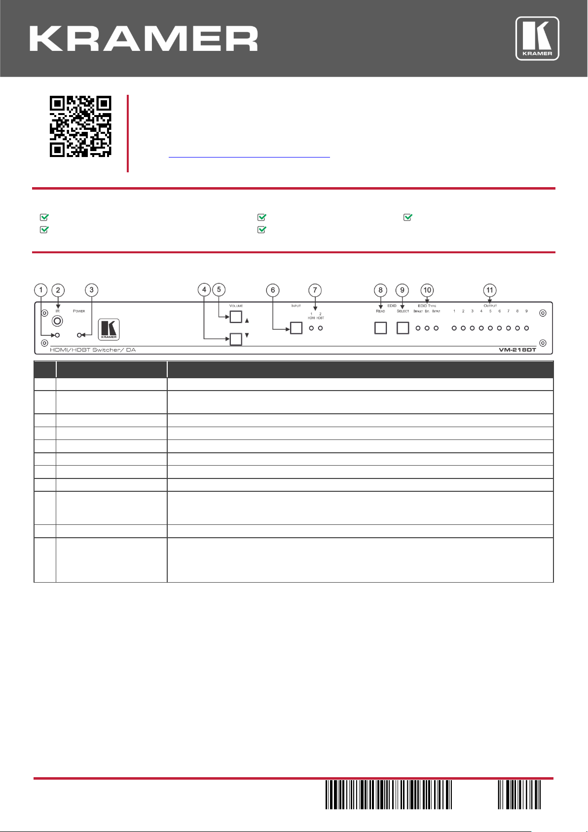
Step 2: Get to know your VM-218DT
#
Feature
Function
1
IR LED
Lights orange when the unit accepts IR remote commands.
2
IR Sensor
Use to control a peripheral device connected to OUT 2 HDBT with that device’s remote
controller.
3
POWER LED
Lights when the unit is powered.
4
VOLUME ()
Press to decrease the volume of the analog audio output.
5
VOLUME ()
Press to increase the volume of the analog audio output.
6
INPUT Selector Button
Press to select input 1 HDMI or input 2 HDBT.
7
INPUT LEDs
Lights green to indicate the selected input: 1 HDMI or 2 HDBT.
8
EDID READ Button
Press to read the selected EDID and write it to both inputs.
9
EDID SELECT Button
Press to cycle through the sources from which to read the EDID: Default, External, or Output.
When Output is selected, cycles through outputs 1 to 9. The relevant EDID TYPE and OUTPUT
LEDs light green.
10
EDID TYPE LEDs
Lights green to indicate the selected EDID type: DEFAULT, EXT. (external) or OUTPUT.
11
OUTPUT LEDs (1 to 9)
In normal operation mode: lights green when an acceptor is connected to the output.
In EDID mode: when EDID TYPE OUTPUT LED lights green, press the EDID SELECT button
briefly to cycle through output 1 to 9 to select the output from which to read EDID. The relevant
LED lights during EDID setup and remains lit after completing the EDID setup.
Page 2
#
Feature
Function
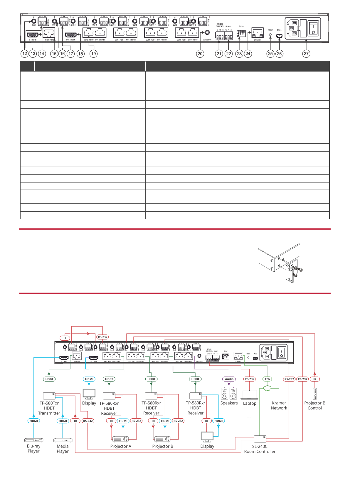
12
IN 2 IR on a 3.5 Mini Jack
Connect to an IR emitter/sensor cable for IR link extension via IN 2 HDBT.
13
IN 2 RS-232 (G, Rx, Tx) Terminal Block
Connector
Connect to a serial controller for RS-232 link extension via IN 2 HDBT.
14
IN 1 HDMI™ Connector
Connect to an HDMI source.
15
IN 2 HDBT on RJ-45 Connectors
Connect to an HDBT transmitter (for example, TP-580Txr).
16
IR OUT on 3.5 Mini Jacks (2 to 9)
Connect to remote IR emitter/sensor cables to IR control the devices that
are connected to the HDBT acceptors.
17
RS-232 OUT (G, Rx, Tx) Terminal Block
Connectors (2 to 9)
Connect to serially control the devices connected to the HDBT acceptors.
18
OUT 1 HDMI Connector
Connect to a local HDMI acceptor.
19
OUT HDBT RJ-45 Connectors (2 to 9)
Connect to HDBT receivers (for example, TP-580Rxr).
20
AUDIO OUT 3.5mm Mini Jack
Connect to an analog audio acceptor.
21
RS-232 CONTROL 3-pin Terminal Block
Connect to the serial controller to control the VM-218DT.
22
REMOTE 3-pin Terminal Block
For future use.
23
SETUP DIP-switches
Use to set the device behavior.
24
ETHERNET RJ-45 Connector
Connect to LAN for remote IP control of the VM-218DT.
25
RESET Button
Press and hold while powering on the device to reset to factory default
parameters.
26
PROG Mini USB Connector
Connect to a PC to perform firmware upgrades.
27
Mains Power Connector, Fuse, and Switch
Connect to the mains supply.
Step 3: Install VM-218DT
Install VM-218DT using one of the following methods:
Remove the three screws from each side of the unit, reinsert those screws through the rack ears
and mount on a 19" rack.
Attach the rubber feet and place the unit on a flat surface.
Step 4: Connect the inputs and outputs
Always switch OFF the power on each device before connecting it to your VM-218DT. For best results, we recommend that
you always use Kramer high-performance cables to connect AV equipment to the VM-218DT.
Page 3

RJ-45 Pinout:
DIP-Switch Settings
For the Ethernet connector, see the wiring diagram
below:
Changes to the DIP-switches only take effect on power-up. After
changing a switch, reboot the device. All DIP-switches are set to Off
(up) by default.
PIN EIA /TIA 568B
PIN
Wire Color
#
Feature
Dip-switch Settings
1
Orange / White
1 Reserved
2
Orange
2 Reserved
3
Green / White
3
Audio deembedding
On (down) – Disable audio de-embedding. Note
that the audio output port is muted.
Off (up) – Enable audio de-embedding to the
analog audio output port (default).
4
Blue
6
Green
7
Brown / White
4 Force RGB
On (down) – Force RGB mode.
Off (up) – Normal mode (default)
8
Brown
For optimum range and performance use the recommended Kramer cables available at www.kramerav.com/product/VM-218DT.
Step 5: Connect the power
Connect the power cord to VM-218DT and plug it into the mains electricity.
Safety Instructions
Caution:
There are no operator serviceable parts inside the unit.
Warning:
Use only the power cord that is supplied with the unit.
Warning:
Do not open the unit. High voltages can cause electrical shock! Servicing by qualified personnel only.
Warning:
Disconnect the power and unplug the unit from the wall before installing.
See www.KramerAV.com for updated safety information.
Step 6: Operate the VM-218DT
Web pages:
RS-232 and Ethernet:
RS-232/Ethernet
Baud Rate:
115,200
Parity:
None
Data Bits:
8
Command Format:
ASCII Protocol 3000
Stop Bits:
1
Example (Route input 1 to output 1):
#ROUTE 1,1,1 <cr>
Ethernet Parameters
IP Address:
192.168.1.39
Subnet Mask:
255.255.0.0
Default UDP Port #:
50000
Default Gateway:
192.168.0.1
Full Factory Reset
Front Panel
Buttons:
Front panel buttons: power off the device, press and hold the
RESET button for 3 seconds while powering the device, and
then release.
Protocol 3000:
“#factory” command.
Web Pages:
In the Device Settings page, click Reset.
Page 4

Technical Specifications
Inputs
1 HDMI
On a female HDMI connector
1 HDBT
On an RJ-45 connector
Outputs
1 HDMI
On a female HDMI connector
8 HDBT
On RJ-45 connector
1 Unbalanced Stereo Audio
On a 3.5mm mini jack
Ports
1 IR IN
On a 3.5mm mini jack for IR link extension via IN 2 HDBT
8 IR OUT
On 3.5mm mini jacks for IR link extension via OUT HDBT (2 to 9)
1 RS-232 IN
On a 3-pin terminal block for serial link extension via IN 2 HDBT
8 RS-232 OUT
On 3-pin terminal blocks for serial link extension via OUT HDBT (2 to 9)
1 Mini USB
On a female USB connector for firmware upgrade
1 RS-232
On a 3-pin terminal block for device control
1 10/100BaseT Ethernet
On an RJ-45 female connector for device control via LAN and Ethernet link
extension via IN HDBT and OUT HDBT (2 to 9)
Extension Reach
4K @60Hz (4:2:0)
Up to 40m (130ft)
Full HD (1080p @60Hz 36bpp)
Up to 70m (230ft)
Compliance
HDBaseT 1.0
Video
Max. Resolution
4K@60Hz (4:2:0) and 4K@30Hz (4:4:4)
Compliance
Supports HDMI 2.0 and HDCP 1.4
RS-232 Extension
Baud Rate
300 to 115,200
Analog Audio
Max Level
1 Vrms
THD + Noise
0.03% @1kHz at nominal level
Controls
Front Panel
Front panel buttons: input select, volume, EDID, IR
Indication LEDs: input select, EDID type, outputs
Rear Panel
RS-232 device control
RS-232 remote control via HDBT ports
IR remote control via HDBT ports
Ethernet device control
DIP-switches
Supported PC Web
Browsers
Windows 7 and Higher
Internet Explorer (32/64 bit) version 10
Firefox version 30
Chrome version 35
MAC
Chrome version 35
Chrome version 63.0.3239.84
Firefox version 30
Firefox version 57.0.2
Safari version 7
Minimum Browser Window Size
1024 x 768 when in full screen mode
Power
Consumption
65VA
Source
100-240V AC, 50/60Hz
Environmental
Conditions
Operating Temperature
0° to +40°C (32° to 104°F)
Storage Temperature
-40° to +70°C (-40° to 158°F)
Humidity
10% to 90%, RHL non-condensing
Regulatory
Compliance
Safety
CE, FCC
Environmental
RoHs, WEEE
Enclosure
Size
19” 1U
Type
Aluminum
Cooling
Fan ventilation
General
Net Dimensions (W, D, H)
43.6cm x 23.7cm x 4.4cm
(17.2” x 9.3” x 1.7”)
Shipping Dimensions (W, D, H)
52.5cm x 33cm x 10.7cm
(20.7” x 13” x 4.2”)
Net Weight
2,47kg (5.5lbs) approx.
Shipping Weight
3.23kg (7.1lbs) approx.
Accessories
Included
Power cord, rack ears
Optional
For optimum range and performance use the recommended USB, Ethernet, serial
and IR Kramer cables available at
www.kramerav.com/product/VM-218DT
Specifications are subject to change without notice at www.kramerav.com
The terms HDMI, HDMI High-Definition Multimedia Interface, and the HDMI Logo are trademarks or registered trademarks of HDMI Licensing Administrator, Inc.
 Loading...