


P/N: 2900-300423 Rev 4 www.kramerAV.com
USER MANUAL
MODEL:
VM-214DT
HDMI/HDBT Switcher/DA

Kramer Electronics Ltd.
VM-214DT – Contents
i
Contents
Introduction 1
Getting Started 1
Overview 2
Defining the VM-214DT HDMI/HDBT Switcher/DA 3
Installing in a Rack 5
Connecting the VM-214DT 6
Connecting to the VM-214DT via RS-232 7
Wiring the RJ-45 Connectors 7
Operating the VM-214DT 8
Acquiring the EDID 8
RS-232 Control and Pass-Through Using the VM-214DT 8
Operating the VM-214DT Remotely Using the Web Pages 11
Browsing the VM-214DT Web Pages 11
The Switching Page 14
The Video and Audio Settings Page 15
The Output Settings Page 16
The EDID Management Page 17
The Data Switching Page 19
The Authentication Page 21
The Device Settings Page 22
The Firmware Upgrade Page 25
The About Us Page 26
Configuring the VM-214DT 27
Setting the DIP-switch 27
Performing a Factory Reset 27
Technical Specifications 28
Default IP Parameters 28
Default Logon Credentials 29
Supported PC Web Browsers 29
Default EDID 30
Protocol 3000 32
Kramer Protocol 3000 Syntax 32
Kramer Protocol 3000 Commands 35

Kramer Electronics Ltd.
VM-214DT – Introduction
1
Introduction
Welcome to Kramer Electronics! Since 1981, Kramer Electronics has been providing a world
of unique, creative, and affordable solutions to the vast range of problems that confront the
video, audio, presentation, and broadcasting professional on a daily basis. In recent years, we
have redesigned and upgraded most of our line, making the best even better!
Congratulations on purchasing your Kramer VM-214DT HDMI/HDBT Switcher/DA. This
product, which incorporates HDMI™ technology, is ideal for:
• Presentation and multimedia applications
• Rental and staging
Getting Started
We recommend that you:
• Unpack the equipment carefully and save the original box and packaging materials for
possible future shipment.
• Review the contents of this user manual.
Go to www.kramerav.com/downloads/VM-214DT to check for up-to-date user manuals,
application programs, and to check if firmware upgrades are available (where appropriate).
Achieving the Best Performance
• Use only good quality connection cables (we recommend Kramer high-performance,
high-resolution cables) to avoid interference, deterioration in signal quality due to poor
matching, and elevated noise levels (often associated with low quality cables).
• Do not secure the cables in tight bundles or roll the slack into tight coils.
• Avoid interference from neighboring electrical appliances that may adversely influence
signal quality.
• Position your Kramer VM-214DT away from moisture, excessive sunlight and dust.
This equipment is to be used only inside a building. It may only be connected to other
equipment that is installed inside a building.
Safety Instructions
Caution: There are no operator serviceable parts inside the unit.
Warning: Use only the power cord that is supplied with the unit.
Warning: Do not open the unit. High voltages can cause electrical shock! Servicing by
qualified personnel only.
Warning: Disconnect the power and unplug the unit from the wall before installing.

Kramer Electronics Ltd.
VM-214DT – Introduction
2
Recycling Kramer Products
The Waste Electrical and Electronic Equipment (WEEE) Directive 2002/96/EC aims to reduce
the amount of WEEE sent for disposal to landfill or incineration by requiring it to be collected
and recycled. To comply with the WEEE Directive, Kramer Electronics has made
arrangements with the European Advanced Recycling Network (EARN) and will cover any
costs of treatment, recycling and recovery of waste Kramer Electronics branded equipment on
arrival at the EARN facility. For details of Kramer’s recycling arrangements in your particular
country go to our recycling pages at www.kramerav.com/support/recycling.
Overview
The VM-214DT HDMI/HDBT Switcher/DA is a switcher/distribution amplifier for HDMI and
HDBT signals. It reclocks and equalizes one of two selectable input signals (HDMI or HDBT)
and distributes it to one HDMI and four HDBT outputs.
In particular, the VM-214DT features:
• Support for 4K UHD (maximum data rate of 10.2Gbps)
• Non-volatile memory that stores the default EDID so it can then provide the EDID
information to the source even if the display device is not connected
• I-EDIDPro™ Kramer Intelligent EDID Processing™, an intelligent EDID handling &
processing algorithm that ensures Plug and Play operation for HDMI systems
• HDMI support for 3D, Deep Color, x.v.Color™ and 7.1 uncompressed audio channels
(Dolby TrueHD, DTS-HD)
• HDCP compliance
• LEDs indicating the selected input and active output
• IR remote control support and a remote IR 3.5mm mini jack
• A 1U rack mount enclosure
• Support for up to 130m (430ft) in normal mode for 1080p @60Hz @36bpp, and up to
100m (328ft) for 4K UHD @30Hz when using BC−HDKat6a cables
Using Twisted Pair Cable
Kramer engineers have developed special twisted pair cables to best match our digital twisted
pair products; the Kramer: BC-HDKat6a (CAT 6 23 AWG cable), and the Kramer:
BC-DGKat7a23 (CAT 7a 23 AWG cable). These specially built cables significantly outperform
regular CAT 6 / CAT 7a cables.
About HDBaseT™ Technology
HDBaseT™ is an advanced, all-in-one connectivity technology (supported by the HDBaseT
Alliance). It is particularly suitable in the ProAV – and also the home – environment as a
digital networking alternative, where it enables you to replace numerous cables and
connectors by a single LAN cable used to transmit, for example, uncompressed, full
high-definition video, audio, IR, as well as various control signals.
The products described in this user manual are HDBaseT certified.

Kramer Electronics Ltd.
VM-214DT – Defining the VM-214DT HDMI/HDBT Switcher/DA
3
Defining the VM-214DT
HDMI/HDBT Switcher/DA
Figure 1: VM-214DT HDMI/HDBT Switcher/DA Front Panel
#
Feature
Function
1
IR LED
Lights yellow when receiving signals from the IR remote sensor
2
IR Remote Control Sensor
Sensor for an IR transmitter. IR data is routed according to the IR routing
configuration, (see The Data Switching Page on page 19)
3
POWER LED
Lights green when the unit receives power
4
VOLUME
Buttons
▼ Down button
Press to decrease the audio volume
5
▲ Up button
Press to increase the audio volume
6
INPUT Button
Press to toggle between HDMI Input 1 and HDBT Input 2. Lights red
when the input is valid, selected and routing to an output(s)
7
1 HDMI LED
Lights green when HDMI 1 Input is selected
8
2 HDBT LED
Lights green when HDBT 2 Input is selected
9
EDID
Buttons
READ Button
Press to read the selected EDID to both inputs, (see Acquiring the EDID
on page 8)
10
SELECT Button
Press to cycle through the EDID sources, (default, external, and each
output) from which to read the EDID. The relevant LED lights green, (see
Acquiring the EDID on page 8)
11
OUTPUT LEDs 1 to 5
In normal operation mode: lights green when an acceptor is connected to
the output.
In EDID mode: Indicates the EDID which is currently stored. The relevant
LED lights during EDID setup and remains lit after completing the EDID
setup, (see Acquiring the EDID on page 8).
12
EDID
TYPE
LEDs
DEFAULT
Lights green when the default EDID is selected, (see Acquiring the EDID
on page 8)
13
EXT.
Lights green when an external EDID is selected
14
OUTPUT
Lights green when one of the output EDIDs is selected

Kramer Electronics Ltd.
VM-214DT – Defining the VM-214DT HDMI/HDBT Switcher/DA
4
Figure 2: VM-214DT HDMI/HDBT Switcher/DA Rear Panel
#
Feature
Function
1
INPUT 1 HDMI Local Input
Connect to the HDMI source
2
INPUT 2 HDBT Remote
Input
Connect to the remote HDBT transmitter, (for example, the WP-20 or
TP-580Txr)
3
OUTPUT 1 HDMI Local
Output
Connect to the HDMI acceptor
4
OUTPUT HDBT
Connectors
2
Connect to the first HDBT acceptor, (for example, the TP-588D)
5 3 Connect to the second HDBT acceptor
6 4 Connect to the third HDBT acceptor, (for example, the TP-580RXR)
7 5 Connect to the fourth HDBT acceptor
8
AUDIO OUT 3.5mm Mini
Jack
Connect to the analog audio acceptor
9
REMOTE IR 3.5mm Mini
Jack
For future use
10
IR 3.5mm Mini Jack
Connect to the remote IR sensor/emitter
11
RS-232 DATA 3-pin
Terminal Block
Connect to the device to be controlled via RS-232
12
RS-232 CONTROL 3-pin
Terminal Block
Connect to the serial controller to control the VM-214DT
13
REMOTE 3-pin Terminal
Block
For future use
14
SETUP 4-way DIP-switch
Used to set the device behavior, (see Setting the DIP-switch
on page 27)
15
ETHERNET RJ-45
Connector
Connect to a remote network controller via a LAN
16
RESET Switch
Press and hold while powering on the device to reset to factory
default parameters, (see Performing a Factory Reset on page 27)
17
PROG Mini USB Connector
Connect to a PC to perform firmware upgrades
18
Mains Power Connector,
Fuse, and Switch
Connect to the mains supply

Kramer Electronics Ltd.
VM-214DT – Installing in a Rack
5
Installing in a Rack
This section provides instructions for rack mounting VM-214DT. Before installing in a rack,
verify that the environment is within the recommended range:
• Operation temperature – 0 to 40C (32 to 104F).
• Storage temperature – -40 to +70C (-40 to +158F).
• Humidity – 10% to 90%, RHL non-condensing.
When installing on a 19" rack, avoid hazards by taking care that:
• It is located within recommended environmental conditions. Operating ambient
temperature of a closed or multi-unit rack assembly may exceed ambient room
temperature.
• Once rack mounted, there is enough air flow around VM-214DT.
• VM-214DT is placed upright in the correct horizontal position.
• You do not overload the circuit(s). When connecting VM-214DT to the supply
circuit, overloading the circuits may have a detrimental effect on overcurrent
protection and supply wiring. Refer to the appropriate nameplate ratings for
information. For example, for fuse replacement, see the value printed on the
product label.
• VM-214DT is earthed (grounded) and connected only to an electricity socket with
grounding. Pay particular attention when electricity is supplied indirectly (for
example, when the power cord is not plugged directly into the wall socket but to an
extension cable or power strip). Use only the supplied power cord.
To rack mount the machine, attach both ear brackets (by removing the
screws from each side of the machine and replacing those screws
through the `ear brackets) or place the machine on a table.
To rack-mount VM-214DT:
Mount the unit in a rack using the recommended rack adapter
(see www.kramerav.com/product/VM-214DT)
Some models, may feature built-in rack ears:
• Detachable rack ears can be removed for desktop use.
• Always mount VM-214DT in the rack before connecting any cables or power.
• Fasten a bracket (included) on each side of the unit and attach it to a flat surface.
For more information go to www.kramerav.com/downloads/VM-214DT.
Kramer Electronics Ltd.
VM-214DT – Connecting the VM-214DT
6
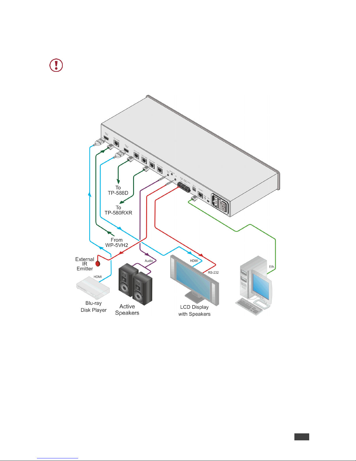
Connecting the VM-214DT
Always switch off the power to each device before connecting it to your VM-214DT. After
connecting your VM-214DT, connect its power and then switch on the power to each
device.
Figure 3: Connecting the VM-214DT HDMI/HDBT Switcher/DA

Kramer Electronics Ltd.
VM-214DT – Connecting the VM-214DT
7
To connect the VM-214DT, as illustrated in the example in Figure 3:
1. Connect the HDMI source (for example, a Blu-ray disk player) to the IN 1 (HDMI)
connector.
2. Connect the HDBT source, (for example, the WP-20) to the Input 2 HDBT connector.
3. Connect the Output 1 HDMI connector to an HDMI acceptor, (for example, an LCD TV
with speakers).
4. Connect the four Output HDBT connectors to up to four HDBT receivers, (for example,
the TP-588D or the TP-580RXR).
5. Connect the Audio Out 3.5mm mini jack to an audio acceptor (for example, active
speakers).
6. Connect an IR emitter to the IR 3.5mm mini jack.
7. Connect the serial RS-232 Data 3-pin terminal block to a device to be controlled, (for
example, the LCD TV connected in step 3).
8. Connect a PC via RS-232 to the RS-232 Control 3-pin terminal block, (see Section
Connecting to the VM-214DT via RS-232 on page 7).
9. Connect the VM-214DT to the mains electricity using the mains cord provided.
Connecting to the VM-214DT via RS-232
You can connect to the VM-214DT via an RS-232 connection using, for example, a PC.
To connect to the VM-214DT via RS-232:
• Connect the 3-pin terminal block serial port on the VM-214DT to the RS-232 9-pin D-sub
port on your PC, (pin Tx to pin 2, pin Rx to pin 3, and G to pin 5)
Wiring the RJ-45 Connectors
This section defines the TP pinout, using a straight pin-to-pin cable with RJ-45 connectors.
EIA /TIA 568B
Figure 4: TP PINOUT
PIN
Wire Color
1
Orange / White
2
Orange
3
Green / White
4
Blue
5
Blue / White
6
Green
7
Brown / White
8
Brown

Kramer Electronics Ltd.
VM-214DT – Operating the VM-214DT
8
Operating the VM-214DT
Acquiring the EDID
Each input on the VM-214DT has a factory default EDID loaded (see Default EDID
on page 30). This lets you connect the power before having to connect one of the acceptors.
The VM-214DT reads the EDID, which is stored in the non-volatile memory.
The following procedure is usually done only once, when the device is being set up.
To acquire the EDID:
1. Press the EDID Select button repeatedly until the required EDID source is selected,
(either Default, Ext, or one of the outputs).
The relevant LED lights green.
2. Press the EDID READ button.
The EDID Read button lights red for a short while and the EDID is copied to the currently
selected input. If the EDID Read button flashes twice after the first flash this indicates
that the EDID was not read and the device reverts to the last stored EDID, as indicated
by the LEDs.
Note: If the EDID READ button is not pressed for five seconds, the procedure is terminated
and the device does not store a new EDID. The last EDID is restored.
The EDID can also be modified using EDID Designer.
RS-232 Control and Pass-Through Using the VM-214DT
The VM-214DT can be controlled via RS-232. As shown in Figure 5, you can connect a PC
(or other serial controller) directly to the VM-214DT to control the VM-214DT.
The VM-214DT also transparently passes bidirectional RS-232 signals over the TP cable from
the TP-580Txr transmitter to the TP-580Rxr receiver. For example, a PC connected to the
RS-232 port on the TP-580Txr can control an RS-232-controllable device (for example, a
projection screen) connected to the TP-580Rxr.
Figure 5: VM-214DT RS-232 Control and Pass-Through
Kramer Electronics Ltd.
VM-214DT – Operating the VM-214DT
9
Local IR Pass-Through and IR Pass-Through Using the
VM-214DT
The VM-214DT provides an IR sensor and a 3.5mm mini jack for connecting a remote IR
emitter or sensor. When the VM-214DT is connected to suitable transmitters and receivers
(for example, the TP-580Txr and TP-580Rxr), the VM-214DT can act as a pass-through for
IR control signals, allowing remote control of multiple devices using multiple IR remote
controllers.
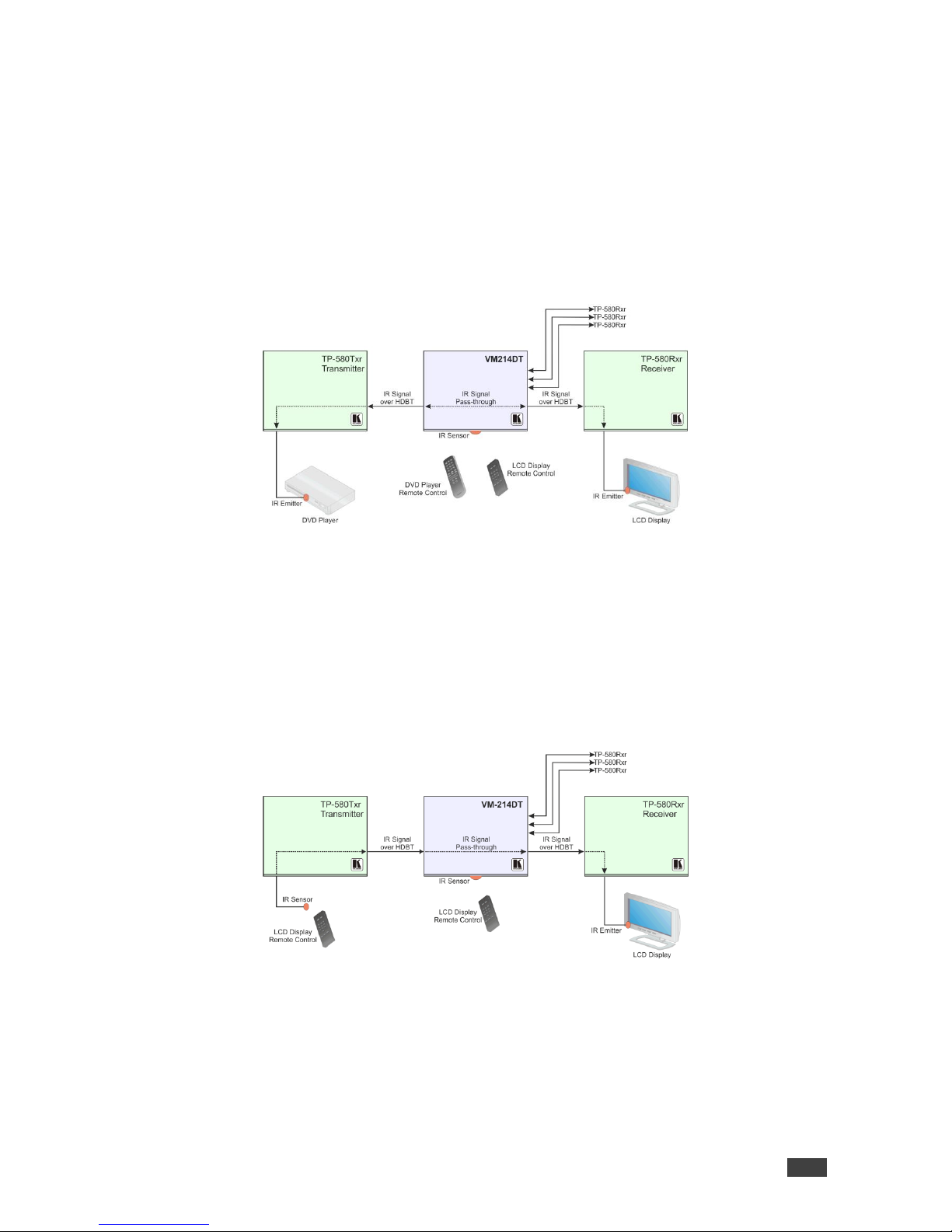
IR Pass-Through Example 1
Figure 6: VM-214DT IR Pass-Through Example 1
• A DVD player is connected to the TP-580Txr transmitter via an IR emitter
• An LCD display is connected to the TP-580Rxr receiver via an IR emitter
• Both the TP-580Txr and the TP-580Rxr are connected to the VM-214DT via TP cabling
Point the appropriate remote control for the device at the VM-214DT IR sensor to control a
device.
IR Pass-Through Example 2
Figure 7: VM-214DT IR Pass-Through Example 2
• An IR sensor is connected to the TP-580Txr transmitter
• An LCD display is connected to the TP-580Rxr receiver via an IR emitter
• Both the TP-580Txr and the TP-580Rxr are connected to the VM-214DT via TP cabling
Point the LCD display remote control either at the TP-580Txr IR sensor or at the VM-214DT
IR sensor to control the LCD display.
Kramer Electronics Ltd.
VM-214DT – Operating the VM-214DT
10
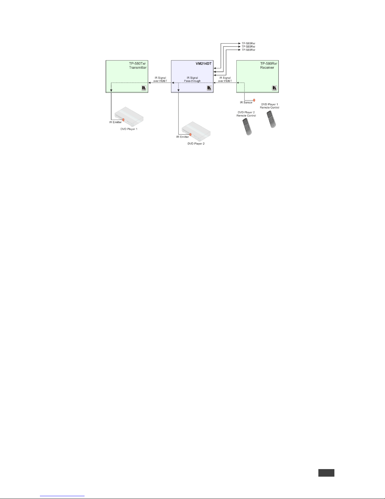
IR Pass-Through Example 3
Figure 8: VM-214DT IR Pass-Through Example 3
• The first DVD player (player 1) is connected to the TP-580Txr transmitter via an IR emitter
• The second DVD player (player 2) is connected to the VM-214DT via an IR emitter
• An IR sensor is connected to the TP-580Rxr receiver
• Both the TP-580Txr and the TP-580Rxr are connected to the VM-214DT via TP cabling
To control DVD player 1, point the DVD player 1 IR remote control at the TP-580Rxr IR
sensor. To control DVD player 2, point the DVD player 2 IR remote control at the TP-580Rxr
IR sensor.

Kramer Electronics Ltd.
VM-214DT – Operating the VM-214DT Remotely Using the Web Pages
11
Operating the VM-214DT
Remotely Using the Web Pages
The VM-214DT can be operated remotely using the embedded Web pages. The Web pages
are accessed using a Web browser and an Ethernet connection.
Before attempting to connect:
• Ensure that your browser is supported (see Default IP Parameters on page 28)
• Ensure that JavaScript is enabled
Browsing the VM-214DT Web Pages
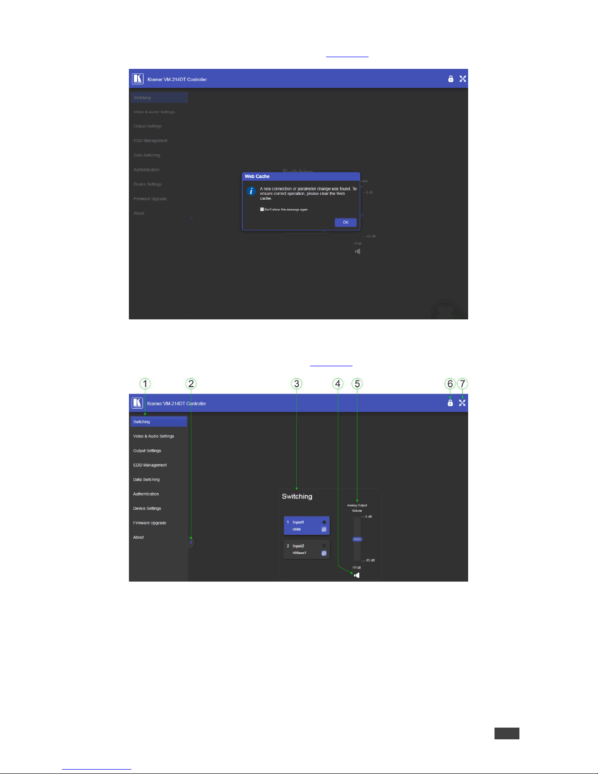
Note: In the event that a Web page does not update correctly, clear your Web browser’s
cache by pressing CTRL+F5.
To browse the VM-214DT Web pages:
1. Open your Internet browser.
2. Type the IP number of the device (see Default IP Parameters on page 28) in the
Address bar of your browser.
Note: If authentication is enabled, the following window appears (Figure 9) and you must
enter the valid username and password to access the Web pages. For default authentication
details, see Default Logon Credentials on page 29.
Figure 9: Entering Logon Credentials
Kramer Electronics Ltd.
VM-214DT – Operating the VM-214DT Remotely Using the Web Pages
12
Following a successful logon, the screen shown in Figure 10 is displayed.
Figure 10: The Default Page
3. Click OK to continue.
The Switching page appears as shown in Figure 11.
Figure 11: The Main Switching Page

Kramer Electronics Ltd.
VM-214DT – Operating the VM-214DT Remotely Using the Web Pages
13
The areas of the main switching page are described in the following table.
#
Item
Description
1
Page Selection Panel
Click one of the buttons to select a page
2
Page Selection Panel
Hide/Reveal Button
Click the arrow to open or close the page selection panel
3
Switching Selection
Click one of the buttons to select an input
4
Mute Button
Click to mute the audio, Click again to unmute the audio
5
Analog Output Volume
Control
Use the slider to control the audio volume
6
Security Indicator
Indicates whether security is enabled (locked) or disabled (unlocked)
7
Full Screen Button
Click to maximize the page
There are nine Web pages described in the following sections:
• Switching (see The Switching Page on page 14)
• Video and Audio Settings (see The Video and Audio Settings Page on page 15)
• Output Settings (see The Output Settings Page on page 16)
• EDID Management (see The EDID Management Page on page 17)
• Data Switching (see The Data Switching Page on page 19)
• Authentication (see The Authentication Page on page 21)
• Device Settings (see The Device Settings Page on page 22)
• Firmware Upgrade (see The Firmware Upgrade Page on page 25)
• About (see The About Us Page on page 26)
Kramer Electronics Ltd.
VM-214DT – Operating the VM-214DT Remotely Using the Web Pages
14
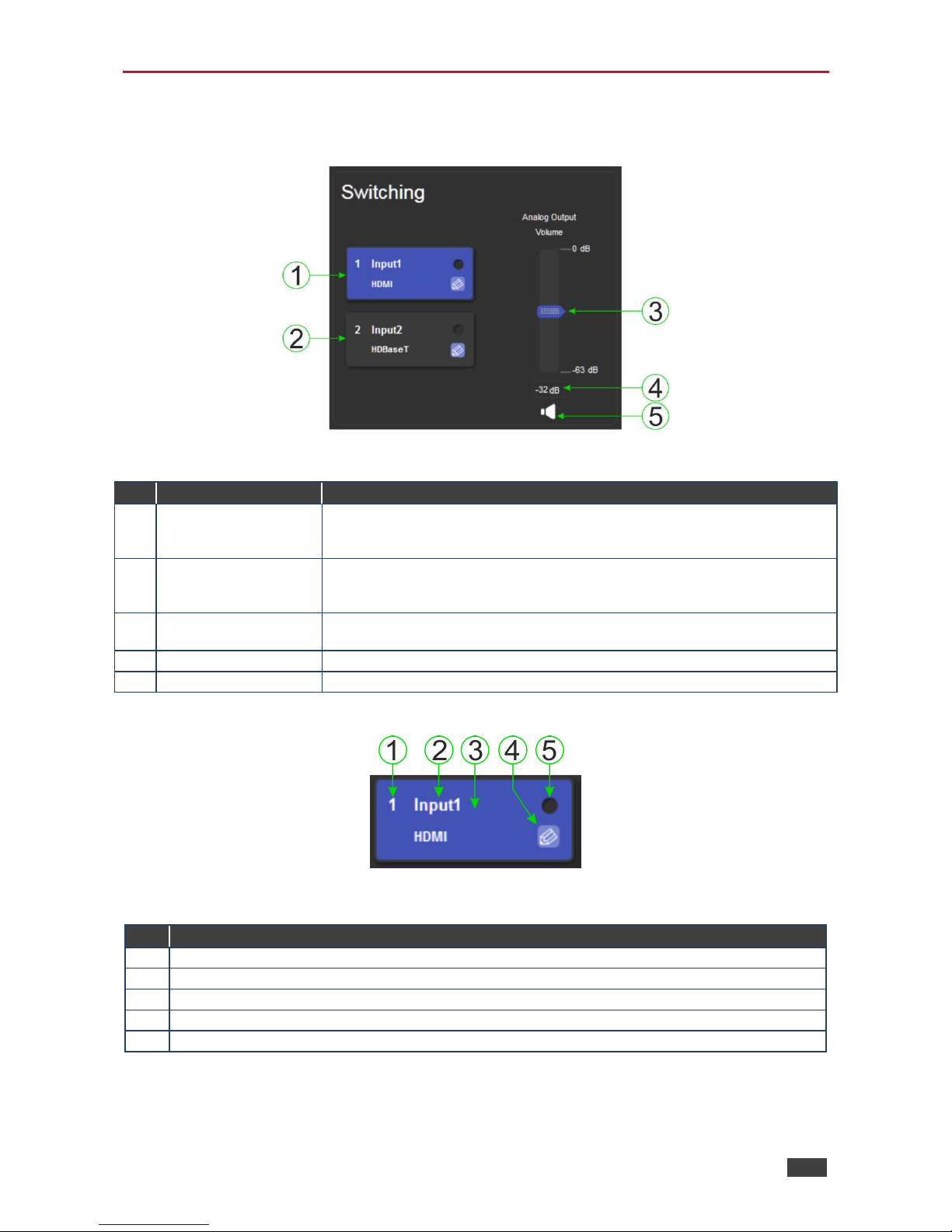
The Switching Page
The Switching page lets you select a video input manually and adjust the audio volume.
Figure 12: The Switching Page
#
Item
Description
1
Input 1 HDMI Button
Click to select the HDMI input. The color of the button indicates whether or
not the input is selected. The color circle indicates whether or not there is a
live signal on the input
2
Input 2 HDBaseT
Button
Click to select the HDBaseT input. The color of the button indicates whether
or not the input is selected. The color circle indicates whether or not there is
a live signal on the input
3
Analog Output Volume
Slider
Slide up to increase the analog output volume or down to decrease the
volume
4
Audio Output Level
Indicates the current audio output level in dB
5
Mute Button
Click to mute or unmute the output audio
The input selection buttons function as described below.
Figure 13: Input Button
#
Description
1
Input number
2
Customizable input button label. See description below
3
Button background color. When the input is selected the background changes from gray to blue
4
Label edit button
5
Live signal indicator. Lights when the input has a live signal on the input
Kramer Electronics Ltd.
VM-214DT – Operating the VM-214DT Remotely Using the Web Pages
15
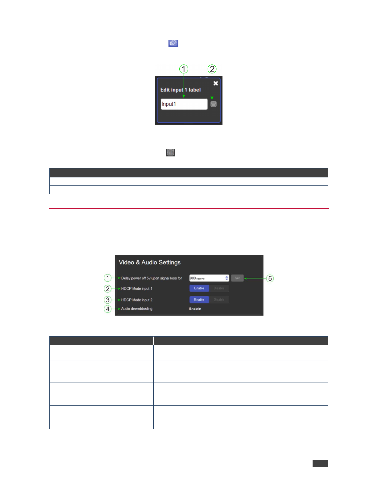
To edit the button label:
1. Click the relevant edit button.
The popup shown in Figure 14 appears.
Figure 14: Input Button Label Editor
2. Enter the required label.
3. Click Enter or the Save button.
#
Description
1
Label text entry box
2
Save button. Click button to save changes after entering the required label text
The Video and Audio Settings Page
The Video and Audio Settings page lets you modify the output power off delay, HDCP support
per input, and audio de-embedding.
Figure 15: The Audio Settings Page
#
Item
Description
1
Delay power off 5V upon signal
loss for Box
Sets the delay for turning off the 5V output because of a signal
loss on the currently selected input. Value in seconds
2
HDCP Mode input 1 Buttons
For Input 1:
Enable—HDCP support is dictated by the display
Disabled—HDCP encrypted content is not passed
3
HDCP Mode input 2 Button
For input 2:
Enable—HDCP support is dictated by the display
Disabled—HDCP encrypted content is not passed
4
Audio de-embedding Indicator
Click enable to de-embed the digital audio
5
Set Button for 5V control upon
signal loss, (see item 1)
Enter the delay in seconds or use the increment/decrement
buttons, then press Set to save the value
Kramer Electronics Ltd.
VM-214DT – Operating the VM-214DT Remotely Using the Web Pages
16
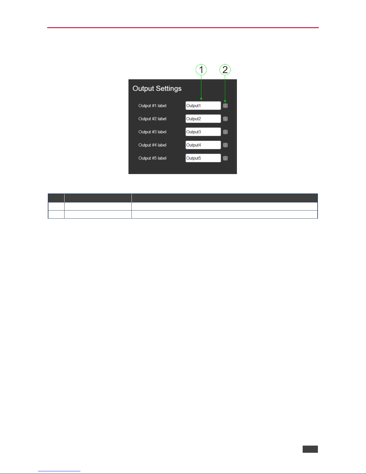
The Output Settings Page
The Output Settings page allows you to custom label the output buttons individually.
Figure 16: The Output Settings Page
#
Item
Description
1
Output Label
Enter the name required for each output
2
Save Button
Click to save the current label
Note: Performing a factory reset returns the labels to their default values.
 Loading...