


KRAMER ELECTRONICS, Ltd.
USER MANUAL
Distribution Amplifiers Models:
VM-1010, VM-1015, VM-1021,
VM-1042, VM-1044, VN-1055, VM-54
IMPORTANT: Before proceeding, please read paragraph entitled
"Unpacking and Contents"
KRAMER ELECTRONICS LTD.

Table Of Contents
Section Name Page
1 INTRODUCTION 1
1.1 A Word On Distribution Amplifiers 1
1.2 Factors Affecting Quality of Results 2
2 SPECIFICATIONS 3
3 HOW DO I GET STARTED? 4
4 UNPACKING AND CONTENTS 4
4.1 Optional Accessories 4
5 VM SERIES AMPLIFIERS 6
5.1 Getting To Know Your VM-1010 Amplifier 6
5.2 Getting To Know Your VM-1015 Amplifier 7
5.3 Getting To Know Your VM-1021 Amplifier 8
5.4 Getting To Know Your VM-1042 Amplifier 10
5.5 Getting To Know Your VM-1044 Amplifier 12
5.6 Getting To Know Your VM-1055 Amplifier 13
5.7 Getting To Know Your VM-54 Amplifier 14
6 INSTALLATION 16
6.1 Rack Mounting 16
7 CONNECTING TO VIDEO DEVICES 16
8 USING THE VIDEO AMPLIFIERS 17
8.1 Powering On The Amplifier 17
8.2 Looping 17
8.3 Level Control 17
8.4 Equalization Control 18
8.5 Coupling 18
8.6 Black Level Clamping 18
8.7 Sync Tip Clamping 19
9 TAKING CARE OF YOUR VIDEO AMPLIFIER 19
10 TROUBLESHOOTING 19
10.1 Power And Indicators 19
10.2 Video Signal 20
Limited Waaranty 21
List Of Illustrations
Figure Page
1 VM-1010 Front/Rear Panel Features 6
2 VM-1015 Front/Rear Panel Features 7
3 VM-1021 Front/Rear Panel Features 8
4 VM-1042 Front Panel Features 10
5 VM-1044 Front/Rear Panel Features 12
6 VM-1055 Front/Rear Panel Features 13
7 VM-54 Front/Rear Panel Features 15
List Of Tables
Table Page
1 VM-1010 Front Panel Features 6
2 VM-1010 Rear Panel Features 7
3 VM-1015 Front Panel Features 8
4 VM-1015 Rear Panel Features 8
5 VM-1021 Front Panel Features 9
6 VM-1021 Rear Panel Features 9
7 VM-1042 Front/Rear Panel Features 11
8 VM-1044 Front/Rear Panel Features 12
9 VM-1055 Front/Rear Panel Features 13
10 VM-54 Front Panel Features 15
11 VM-54 Rear Panel Features 16
12 Signals Supported By Model 16
KRAMER ELECTRONICS LTD.
i

INTRODUCTION
Congratulations on your purchase of this Kramer Electronics amplifier. Since 1981 Kramer has been
dedicated to the development and manufacture of high quality video/audio equipment. The Kramer
industrial line has become an integral part of many of the best production and presentation facilities
around the world. In recent years, Kramer has redesigned and upgraded most of the industrial line,
making the best even better. Kramer’s line of professional video/audio electronics is one of the most
versatile and complete available, and is a true leader in terms of quality, workmanship,
price/performance ratio and innovation. In addition to the Kramer line of high quality amplifiers, such
as the one you have just purchased, Kramer also offers a full line of high quality industrial and
broadcast switchers, processors, interfaces, controllers and computer-related products. Kramer
welcomes your inquiries for Kramer equipment or custom-manufactured products, engineering, private
labeling and OEM manufacturing per your specifications.
This manual includes configuration, operation and information for the following products from the
Kramer VM line of distribution amplifiers. All these VM amplifiers are similar in operation and
features.
VM-1010 - 1:10 Video Distributor
VM-1015 - 1:5 Video Distributor
VM-1021 - 1:20 Video Distributor
VM-1042 - 4:2 Video Component Distributor
VM-1044 - 4:4 Video Distributor
VM-1055 - 1:5 Five Channel Video Component Distributor
VM-54 - Looping Video Distributor
A Word On Distribution Amplifiers
Distribution amplifiers are used to distribute one source to several acceptors for simultaneous
recording or monitoring of one source, with no discernible signal degradation. They vary in the
number of inputs, looping capability, programming capability, number of outputs, operating format,
bandwidth and input/output coupling. A good quality distribution amplifier amplifies the incoming
signal, pre-compensates the signal for potential losses (resulting from the use of long cables, noisy
source, etc.) and generates several identical buffered and amplified outputs. Often, a signal processor is
inserted between the source and the distribution amplifier for correction and fine-tuning of the source
signal before multiplication, so that all copies are corrected in the same way. The front panels of these
Kramer amplifiers are designed to be simple to operate.
KRAMER ELECTRONICS LTD.
1

Factors Affecting Quality of Results
There are many factors affecting the quality of results when signals are transmitted from a source to an
acceptor:
Connection cables - Low quality cables are susceptible to interference, they degrade signal quality due
to poor matching and cause elevated noise levels. They should therefore be of the best quality.
Sockets and connectors of the sources and acceptors - So often ignored, they should be of highest
quality, since "Zero Ohm" connection resistance is the target. Sockets and connectors also must match
the required impedance (75ohm in video). Cheap, low quality connectors tend to rust, thus causing
flaws in the signal path.
Amplifying circuitry - Must have quality performance when the desired end result is high linearity,
low distortion and low noise operation.
Distance between sources and acceptors - Plays a major role in the final result. For long distances
(over 15 meters) between sources and acceptors, special measures should be taken in order to avoid
cable losses. These include using higher quality cables or adding line amplifiers.
Interference from neighboring electrical appliances - These can have an adverse effect on signal
quality. Balanced audio lines are less prone to interference, but unbalanced audio should be installed
far from any mains power cables, electric motors, transmitters, etc. even when the cables are shielded.
KRAMER ELECTRONICS LTD.
2

SPECIFICATIONS
VM-1010 VM-1015 VM-1021 VM-1042 VM-1044 VM-1055 VM-54
Configuration
Input Type
Input
Connections
Input Level
Output Type
Output
Connector
Output Level
Output
Coupling
S/N Ratio
Bandwidth
Differential
Gain
Differential
Phase
K-Factor
Non Linearity
EQ. Control
DC Clamp
Level Control
Dimensions
Weight
Power
consumption
Power Source
2X CV 1X CV 1X CV 4XCV/RGB 4XCV/RGB 5XCV/ RGB
CV CV CV CV/RGB CV/RGB CV/RGB HSVS CV/Comp
BNC BNC BNC BNC BNC BNC BNC
1Vpp/75
looping
1X10 or 2X5 5XCV CV 3Vpp Max. 2X4 CV/RGB
BNC BNC BNC BNC BNC BNC BNC
1Vpp/75 1Vpp/75 1Vpp/75 1Vpp/75 1Vpp/75 1Vpp/75 1Vpp/75
DC/AC AC/ DC/
74dB 75dB 74dB 73dB 74dB 74dB 70dB
220MHz –3dB 340MHz -3dB 350 MHz -3dB 200 MHz -3dB 320 MHz -3dB 300 MHz -3dB 350MHz
0.05 %. 0.08 %. 0.1 %. 0.05 %. 0.05 %. 0.1 %. 0.03%
0.05Deg 0.12Deg 0.07Deg 0.05Deg 0.05Deg 0.1Deg 0.09Deg
<0.05%. <0.03%. <0.03%. <0.05%. 0.1%. 0.05%. <0.05%
0.2% <0.1%. 0.1%. <0.1%. <0.1%. 0.1%. 0.2%
0-2.5dB @
100% color bar,
4.43MHz
Not clamped 0 VDC Black
-1.4db-+2.5db -1.2db-+2.8db
19 inch (W),
7 inch (D), 1U
(H) 48.26
cm x 17.78 x
4.5cm
2.5Kg
(5.55Lbs.)
Approx.
10.3VA 4.6VA 6.7VA 3.2VA 4.6VA 5.3VA 21.39VA
230V/115VAC
50/60Hz
1Vpp/75
looping
Clamped
0-2.7dB @
100% color bar,
4.43MHz
Level, or sync
bottom TIP
(trimmer)
19 inch (W),
7 inch (D), 1U
(H) 48.26
cm x 17.78 x
4.5cm
2.420Kg
(5.38Lbs)
Approx.
230V/115VAC
50/60Hz
1Vpp/75
looping
AC/ DC/
Clamped
0-2.9dB @
100% color bar,
4.43MHz
0 VDC Black
Level, or sync
bottom TIP
4 accessible
trimmers
19 inch (W),
7 inch (D), 1U
(H) 48.26
cm x 17.78 x
4.5cm
2.660Kg
(5.91Lbs)
Approx.
230V/115VAC
50/60Hz
1Vpp/75
looping
2Vpp
DC DC DC DC/AC
0-1.3dB @
100% color bar,
4.43MHz
Not clamped Not clamped Not clamped Not clamped
-2.2db-+2.0db -1.1db-+2.5db Fixed gain=1 24 accessible
19 inch (W),
7 inch (D), 1U
(H) 48.26
cm x 17.78 x
4.5cm
2.5Kg
(5.55Lbs.)
Approx.
230V/115VAC
50/60Hz
1Vpp/75 1Vpp/75 1Vpp/75
4X4 CV/RGB 5X5CV/ RGB
0-0.9dB @
100% color bar,
4.43MHz
19 inch (W),
7 inch (D), 1U
(H) 48.26
cm x 17.78 x
4.5cm
2.540Kg
(5.64Lb)
Approx.
230V/115VAC
50/60Hz
HSVS
HSVS
No equalization 0 to 2.3dB
19 inch (W),
7 inch (D), 1U
(H) 48.26
cm x 17.78 x
4.5cm
2.660Kg
(5.91Lbs)
Approx.
230V/115VAC
50/60Hz
1X CV, 3comp
looping
3x18
Composite/ CV
trimmers
19 inch (W),
7 inch (D), 2U
(H) 48.26
cm x 17.78 x 9
cm
3.980Kg
(8.84Lbs)
Approx.
230V/115VAC
50/60Hz
KRAMER ELECTRONICS LTD.
3

HOW DO I GET STARTED?
The fastest way to get started is to take your time and do everything right the first time. Taking 15
minutes to read the manual may save you a few hours later. You don’t even have to read the whole
manual. At the beginning of each section, you’ll find an overview of the section. So if the section
doesn’t apply to you, you don’t have to spend your time reading it.
UNPACKING AND CONTENTS
The items contained in your Kramer VM Amplifier packaging are listed below. Please save the
original box and packaging materials for possible future transportation and shipment of the Amplifier.
Amplifier (rack-mountable)
AC power cable
User Manual
Kramer concise product catalog
4 rubber feet
For additional information regarding optional cables and optional accessories contact your Kramer
dealer.
Optional Accessories
The following Kramer accessories can enhance implementation of your amplifier.
SP-11 - (Video/Audio Processor) can be serially connected between the video/audio source and the
VM amplifier for video and audio control/correction. The machine provides camera control and
luminance/white balance correction. The SP-11 is also capable of performing Composite to Y/C
conversion and bi-directional transcoding. The machine allows full control over the video signal:
Video gain down to full fade, log or linear Definition control, log or linear Contrast control, Color
saturation control, Black Level control, Red, Green and Blue controls and a Screen Splitter control
for “before-after” comparison. The Input switch control is "Audio-follow-Video".
SP-3001 - (Component Video Processor) can be serially connected to the VM amplifier in order to
achieve full control of component video. The SP -3001 has 3 looping Component Video inputs and 9
outputs- three for each component; thus it serves as a Component DA as well. The SP -3001 allows
full control of Gain, Contrast, Definition and black level of the Y channel and individual Gain and
Black level controls of the R-Y and B-Y channels. A Screen Splitter control for "before-after"
comparison is also built in.
VS-2516 - (Programmable Vertical Interval Matrix Switcher) can be serially connected to the VM
amplifier for input switching and source selection. The VS -2516 serves as a 16x16 Composite Video
switcher, as an 8x8 Super Video (YC) switcher, as a 4x4 RGBS or as a 5x5 YUV switcher. It may be
connected to a VS-2216/VS-2616 (16x16 Audio Matrix Switchers) for "Audio follow Video"
applications. The VS -2516 has very low cross talk and wide frequency response, DC coupled
outputs, with RS-232 interface built-in, (software provided), LCD panel read-out, LED status
display, up to 15 setups savable in non-volatile RAM, and is microprocessor controlled with user
programmable settings. It can be easily extended up to 96x96 by using additional machines.
VP-102 (VGA to RGBS Converter) is a full bandwidth VGA to RGBS Converter especially
designed for computer, workstation and presentation applications, and for simplifying computer
graphics distribution. The machine may be installed between a PC and one of the DA's for
conversion between the DB-15 connector type signals, to a signal appropriate to the DA. This is
implemented by using the VP-102 as a converter from VGA/Super - VGA/XGA graphics output to
KRAMER ELECTRONICS LTD.
4

Red, Green, Blue, Horizontal/Composite sync and Vertical Sync signals available on BNC
connectors. The VP-102 allows the user to select either a Composite or Horizontal sync output and
the Green output either includes Composite sync or is blanked.
SG-11 (Sync-Green Adder/Separator) is used for adding a sync signal to the "GREEN" channel
prior to distribution. The SG-11 interfaces between the two most widely used professional
Component Video formats: RGB with Sync on Green and RGBS. The SG-11 either combines Sync
with Green or splits Green & Sync signal to separate Green and Sync on the BNC connectors.
TP-1 (Video Line Transmitter). If one of the DA outputs is sent over a long distance (100 meter or
more), it is necessary to convert the signal to twisted pair type. The TP-1 sends a color video signal
over long distances using telephone wire or any other twisted pair wire thus extending the range of
operation of a DA. The TP-1 maintains the bandwidth of an industrial color video signal up to
several hundred meters and of broadcast quality (up to 12 MHz) signals up to 100 meters. At shorter
distances, as in a studio, bandwidth of 30 MHz is easily achieved. By using the KRAMER TP-1
together with the TP-2 (Video Line Receiver) coax wiring (in a studio for example) can be
completely eliminated. The TP-1 can also be used for simplification of security and CCTV
installations, and for teleconferencing in offices and hospitals using existing intercom or telephone
wiring.
VA-11AV - (Video/Audio Combiner) Used to distribute audio/video signals. The machine can be
inserted in front of a DA, allowing the DA to distribute a video signal and two audio signals
simultaneously. It sends a color video signal and a stereo audio signal using only one standard coax
cable in real time. The machine maintains the bandwidth of an industrial color video signal and the
output signal may be viewed and recorded as a normal video signal. By using the VA-11AV together
with the VA-12AV (Video/Audio Separator) the audio stereo signal may be recovered so audio
signals may be sent in a hidden mode, to be recovered only by the VA-12AV. The VA-11AV can be
used for simplification of security and CCTV installations, using existing video coax wiring for
video and audio transmissions.
611T/611R - (611T full bandwidth Fiber Optic Transmitter and 611R matching Fiber Optic
Receiver) Part of the KRAMER TOOLS series, and designed for studio and other demanding
applications. These machines, in combination, may be used to send one of the distributed channels to
distances of 5-25Km. The 611T and 611R use state-of-the-art fiber optic circuitry and allow the user
(via rear panel trimmers) to adjust input and output video levels and high frequency peaking to
achieve best performance. Both machines, like all KRAMER TOOLS, are fed from a 12VDC source,
making them perfectly suitable for fieldwork as well.
VIDEO TESTER - A new, unique, patented, indispensable tool for the video professional, the
Video Tester is used to test a video path leading to/from an amplifier. By pressing only one touch
switch it can trace missing signals, distinguish between good and jittery (VCR sourced) signals, and
identify the presence of good signals. Whenever a video signal is missing, because of bad
connections, cable breaks or faulty sources, the Video Tester is all you need.
KRAMER ELECTRONICS LTD.
5
VM SERIES AMPLIFIERS
This section describes all the controls and connections of your amplifier. Understanding all of the
controls and connections helps you realize its full power.
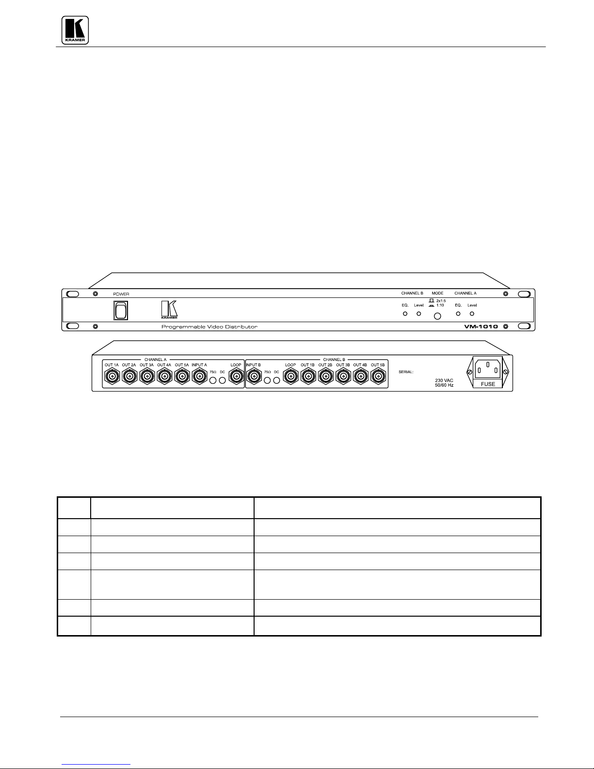
Getting To Know Your VM-1010 Amplifier
The KRAMER VM-1010 is full broadcast, state-of-the-art, Programmable Video Distribution
Amplifier designed for studio and other demanding applications. The VM-1010 has two looping video
inputs, each splitting to 5 outputs. The user may select 2x1:5 or 1:10 operation via front panel control
switches. Several VM-1010 units may be chained through the looping inputs. Output signals are (user
selectable) DC or AC coupled for maximum flexibility.
Front/rear panel features of the VM-1010 are described in Figure 1, Table 1 and Table 2.
No.
1.
2.
3.
4.
5.
6.
Figure 1: VM-1010 Front/Rear Panel Features
Table 1: VM-1010 Front Panel Features
Feature
Function
Power Switch Illuminated switch: Supplies power to the unit.
EQ trimmer (CHANNEL B) Controls cable equalization of channel B outputs.
Level trimmer (CHANNEL B) Controls video level of channel B outputs.
MODE (2 x 1:5, 1:10)
Selects either 1:10 or 2 x 1:5 operation.
pushbutton
EQ trimmer (CHANNEL A) Controls cable equalization of channel A outputs.
Level trimmer (CHANNEL A) Controls video level of channel A outputs.
KRAMER ELECTRONICS LTD.
6
 Loading...