

Page 1

www.kramerAV.com
info@kramerel.com
Installation Instructions
MODEL:
T1AF-114
Inner Frame
P/N:
29 00- 30 1426QS
Rev:
1
SAFETY WARNING
Disconnect the unit from the power supply before opening and servicing
For the latest information on our products and a list of Kramer distributors, visit our
Web site where updates to these installation instructions may be found.
We welcome your questions, comments, and feedback.
Page 2
2
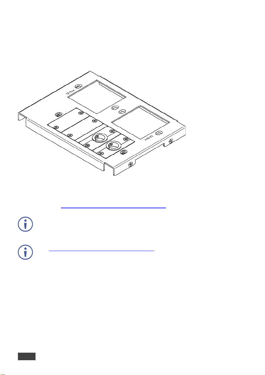
T1AF-114 Inner Frame
T1AF-114 Inner Frame
Congratulations on purchasing your Kramer Kramer T1AF-114 Inner Frame for
TBUS-1AXL, TBUS-1-KWC and TBUS-1N.
T1AF-114 includes:
• 2 openings for 2 single power sockets.
• 1 opening with 2 blank inserts and 2 cable pass-through inserts.
Power Socket and Power Cord Options
Various power sockets and power cords are available to use with the T1AF-114, as
described in the “TBUS Modular Power Socket Installation and Power Cord” Installation
Instructions (see www.kramerav.com/downloads/T1AF-114), supplied with the power
socket.
Each power socket comes with detailed assembly instructions.
Mounting Inserts
Go to www.kramerav.com/downloads/T1AF-114 to download the latest user manual
and the complete list of Kramer wall plates and module connectors.
You can rearrange or remove any of the plates mounted on the inner frame and replace
them with Kramer passive wall plates or connector modules for interfacing A/V type signals.
To mount a Kramer insert or connector module:
1. Unscrew the two screws that fasten the blank plate to the inner frame and remove the
blank plate.
2. Place the required Kramer insert over the opening, insert the two screws to fix the
Kramer insert in place, and tighten them.
Page 3

Installation Instructions
3
Installing the Assembled Inner Frame
To install the T1AF-114 inner frame:
1. Place the assembled inner frame inside the TBUS enclosure.
2. Set the required height using your fingers to bring the inner frame to the desired
position, screw and tighten it in place using the height adjustment screws supplied with
the inner frame.
Connecting the Cables
To connect the cables when replacing blank inserts with connector inserts (for
example, VGA, audio, HDMI and so on):
1. Insert the cables to their appropriate connectors from underneath.
2. Secure the cables to the tie holes on the TBUS. Do not secure the cables too tightly or
too loosely. Leave a small amount of slack.
Inserting Pass-through Cables
To insert the pass-through cables (for example, to connect a laptop) do the
following:
1. Remove the two screws attaching the split pass-through bracket.
2. Remove the split grommet(s).
3. Insert the cable(s) through the rectangular opening.
4. Open the split grommet slightly and insert the required cables.
5. Place the split bracket around the grommet and position this assembly over the inner
frame.
6. Place the two screws appropriately and tighten the split bracket together with the
grommet and inserted cables to the inner frame.
7. Insert the self-locking ties through the tie holes to secure the cables to the inside walls
of the enclosure.
 Loading...