

Page 1

Kramer Electronics, Ltd.
USER MANUAL
Model:
SV-552/SV-552 ALC
SummitView™ Processor/Switcher
Page 2

Contents
i
Contents
1 Introduction 1
2 Getting Starte d 1
PART I Your SummitView™ System 2
3 Overview 2
3.1 Basic SummitView™ SV-552 Installation 2
3.2 Shielded Twisted Pair and Unshielded Twisted Pair 3
3.3 8-Step SummitView™ Basic System Quick Installation Guide 4
PAR T II The SV-552 SummitView™ Processor/Switcher 6
4 Defining the SV-552 Processor/Switcher 6
4.1 DDC Support 9
PAR T II I Detailed Installation Instructions 10
5 Connecting the SV-552 SummitView™ Processor/ Switcher 10
5.1 Connecting the SV-552 Processor/Switcher 10
5.2 Operating the SV-552 Processor/Switcher Remotely 11
5.3 Installing the SV-552 in a 19” Rack (Optional) 12
6 The RC-63DL Room Controller 13
6.1 Defining the RC-63DL 13
6.2 Connecting the Room Controller 15
7 Defining and Connecting the Wall Plates 16
7.1 Defining the Wall Plates (U.S.) 17
7.1.1 Defining the SV-301xl (U.S.) 17
7.1.2 Defining the SV-302 (U.S.) 19
7.1.3 Defining the SV-306 (U.S.) 20
7.1.4 Defining the SV-307 (U.S.) 21
7.2 Defining the Wall Plates (England and Europe) 22
7.2.1 Defining the SV-301xl (England and Europe) 22
7.2.2 Defining the SV-302 (England and Europe) 23
7.2.3 Defining the SV-306 (England and Europe) 24
7.3 Connecting the Wall Plates to the SV-552 25
7.3.1 Connecting the SV-301xl Wall Plate to the SV-552 25
7.3.2 Connecting the SV-302 Wall Plate to the SV-552 26
7.3.3 Connecting the SV-306 Wall Plate to the SV-552 (Optional) 27
8 Wiring the TP Line In/Line Out Connectors 28
8.1 Wiring the Twisted Pair RJ-45 Terminals (U.S.) 28
8.2 Wiring the Terminal Block (England and Europe) 29
8.3 Cabling for the SV-306 and SV-307 30
9 Grounding the Wall Plate 30
PA RT IV Further information 32
10 Customizing the Controllers' Buttons and Labels 32
Page 3

KRAMER: SIMPLE CREATIVE TECHNOLOGY
Contents
ii
10.1 Backlit Buttons 32
10.2 Button Label Sheet 32
11 SummitView™ System Cables 33
12 SummitView™ Cable Termination 34
13 Technical Specifications 36
14 ADA Requirements 37
15 SV-552 SummitVie w™ Essentials Basic System Check List 39
Figures
Figure 1: SV-552 SummitView™ P rocessor / Switcher Front and Rear Panels 7
Figure 2: SV-552 SummitView™ Processor / Switcher Underside
9
Figure 3: Connecting the SV-552
11
Figure 4: RC-63DL Room Controller Front Panel 14
Figure 5: RC-63DL Room Controller Rear Panel
14
Figure 6: Connecting the RC-63DL to the SV-552 SummitView™ Processor/Switcher
16
Figure 7: Connecting the SV-301xl to the SV-552
25
Figure 8: Connecting the SV-3 02 t o the SV-552 26
Figure 9: Connecting the SV-306/307 to the SV-552
27
Figure 10: Wiring the K-Net Connector
31
Figure 11: Sample Button Labels Sheet
32
Figure 12: Stickers Affixed to Cables 35
Figure 13: Overhead and Side Clearance Requirements
37
Figure 14: High/Low Forward, Side and Over Obstruction Reach Limit Requirements
38
Page 4

Contents
iii
Tables
Table 1: Quick Installation Guide for the SummitView™ Basic S ystem 4
Table 2: SV-552 SummitView™ Processor/Switcher Underside Features 8
Table 3: SV-552 SummitView ™ Proc e s s or/ Switcher Underside Features
9
Table 4: RC-63DL Room Controller Front Panel Features
14
Table 5: RC-63DL Room Controller Rear Panel Features
15
Table 6: Defining the SV-301xl (U.S.) 17
Table 7: Enclosing a Wall Plate (U.S.) in its Plastic Frame
18
Table 8: Defining the SV-302 (U.S.)
19
Table 9: Defining the SV-306 (U.S.)
20
Table 10: Defining the SV-307 (U.S.) 21
Table 11: Defining the SV-301xl (England and Europe)
22
Table 12: Defining the SV-302 (England and Europe)
23
Table 13: Defining the SV-306 (England and Europe)
24
Table 14: UTP Pinout (U.S.)
29
Table 15: Terminal Block Pinout (England and Europe) 29
Table 16: Grounding Screw, Lock Washers and Ring Tongue Terminal
30
Table 17: Recommended Cables for use with SummitView™ Systems
33
Table 18: SummitView™ Cable Termination
34
Table 19: Technical Specifications of the SV-552 Proce ss or / Switcher 36
Table 20: SV-552 SummitView™ Basic System Check List
39
Page 5

Introduction
1
1 Introduction
Welcome to Kramer Electronics! Since 1981, Kramer Electronics has been providing
a world of unique, creative, and affordable solutions to the vast range of problems
that confront the video, audio, presentation, and broadcasting professional on a daily
basis. In recent years, we have redesigned and upgraded most of our line, making the
best even better! Our 1,000-plus different models now appear in 11 groups
1
that are
clearly defined by function.
Congratulations on purchasing your Kramer SummitView™ system! This user
manual is comprised of four parts:
PART I: A description of the SummitView™ system, its devices and a quick start
section
PART II: A definition of the SV-552 SummitView™ Processor/Switcher
PART III: Detailed ins ta lla tion instructions for install ing the wall plates and
connecting the SV-552 SummitView™ Processor/Switcher
PART IV: Further information
2 Getting Started
We recommend that you:
• Unpack the equipment carefully and save the original boxes and packaging
materials for possible future shipment
• Review the contents of this user manual
2
1 GROUP 1: Distribution Amplifiers; GROUP 2: Switchers and Matrix Switchers; GROUP 3: Control Systems; GROUP 4:
Format/Standards Converters; GROUP 5: Range Extenders and Repeaters; GROUP 6: Specialty AV Products; GROUP 7: Scan
Converters and Scalers; GROUP 8: Cables and Connectors; GROUP 9: Room Connectivity; GROUP 10: Accessories and Rack
Adapters; GROUP 11: Sierra Products
2 Download up-to-date Kramer user manuals from
http://www.kramerelectronics.com
Page 6

KRAMER: SIMPLE CREATIVE TECHNOLOGY
Overview
2
PART I Your SummitView™ System
PART I describes the SummitView™ system and its devices
3 Overview
We have designed a complete and simple solution for the integration of media and
control in classrooms, training rooms and presentation rooms. SummitView™ is as
easy to use as it is to specify and install. The components that make up the
SummitView™ system are also available as standalone products. With a
SummitView™ kit, you get everything you need for a high end integrated media system
– just add the mounting hardware, displays, and sources. All the signals are transmitted
over economical TP cable and switched using the SV-552 Switcher/Processor.
The SV-552 ALC version is aimed at installers who p refer to design their own
SummitView installations. The SV-552 ALC kit differs from the standard SV-552
only in regards to the contents of the box (see
Section 15
The SummitView™ System controlled via th e n etw ork is everything you need from the
company you can count on for quality products and the ultimate in customer support –
Kramer Electronics.
).
3.1 Basic SummitView™ SV-552 Installation
The usual SummitView™ SV-552 installation includes t he following:
• SV-552 ALC SummitView™ Processor/Switcher
• SV-301xl, SV-302 and SV-306 Wall Plates
• RC-63DL Room Controller
• SPK-CC444 Speakers
• Power adapter (12V DC output)
• Required cables (for details see
Section 11
• Check list (see
)
Table 20)
The following additional products are available for purchase:
• SV-301xl, SV-302, SV-306 and SV-307 Wall Plates
1
and compatible cables
• Kramer Pico TOOLS™ FC-200 EDID Copier
• RC-63D series (RC-63D, RC-63DL), RC-53D series, and RC-63A series
(RC-63A, RC-63AL) Room Controllers
2
• A range of ceiling and wall mounted speakers
1 Download the user manual: SV-301/301xl/302/303/304/305/306/307 from http://www.kramerelectronics.com
2 Download the RC-53D user manual from
http://www.kramerelectronics.com
Page 7
Overview
3
• MT-P9P 9” and MT-P6P 6” center pole sections for the SV-1 Mounting Box
which can be attached to any 1.5NFS projector mounting system
• SV-1 Pole Mounting Box which can be attached to any 1.5NFS projector
mounting s yst e m
• Additional TP cables (see
Section 11
The following items are not provided by Kramer :
)
• Projector (or display device)
• Screen (and mounti ng hardwa re)
• Source devices, such as, DVD/VCR player, scanner, or computer
• Installation hardware (where needed), such as, bolts for concrete structural
ceilings, toggles (used for sc reen mounti ng on dry wall), and so on
To achieve the best performance:
• Consider the condition of the room—its size, the way it is arranged, whether the
walls and ceiling are drywall or cement—that may limit where and how you can
install the SummitView™, where required, refer to the ADA requirements
(see
Section 14).
Where an internal installation is impractical (for example, if the walls and
ceiling are constructed of cement and you do not want to drill inside them), you
can install the SummitView™ system externally, that is, install the SV-552 in a
rack (see
5.2Section
• Connect only good quality connection cables and avoid interference from
neighboring electrical appliances and position your SummitView™ away from
moisture, and excessive sunlight
) using the RK-551 rack mount ki t
3.2 Shielded Twisted Pair and Unshielded Twisted Pair
We recommend that you use Shielded Twisted Pair (STP) cable. There are different
grades of STP cable available, and we advise you to use the best quality STP cable
that you can afford. Our non-skew-free cable, Kramer BC-STP is intended for
digital signals and for analog signals where skewin g is not an issue. For ca s es where
skewing occurs, our UTP skew-free cable, Kramer BC-XTP, should be used. Bear in
mind, though, that we advise using STP cables where possible, since the compliance
to electromagnetic interference has been tested using STP cables.
Althoug h Unshielded Twisted Pair (UTP) cable might be preferred for long range
applications, UTP cable should be installed as far as possible from electric cables,
motors, and so on, as these devices tend to create electromagnetic interference.
Page 8
KRAMER: SIMPLE CREATIVE TECHNOLOGY
Overview
4
However, since the use of UTP cable might not conform to electromagnetic
standards, Kramer does not commit to meeting the standard with UTP cable.
3.3 8-Step SummitView™ Basic System Quick Installation Guide
The following guide summarizes how to install a SV-552 SummitView™ basic
system (similar principles appl y if you are installing other SummitView™
configurations).
Table 1: Quick Installation Guide for the SummitView™ Basic System
Description
1 Prepare the openings for the wall plates and the room controller.
2 Route the wiring from the proposed
location of the SV-552 via:
1. STP
1
, BC-DGKat524 or
BC-DGKat-623 (SV-306/307) cable
to the intended wall plate locations.
2. K-Net cabling to the intended
RC-63DL location.
3. Speaker cabling to the intended
location of the speakers.
4. If t he SV-552 and/or the RC-63DL
are to be used as room controllers,
route the appropriate control
cable s t o the ir i n ten de d loc ati o ns.
3 Install the wall plates by connecting the:
1. STP, BC-DGKat524 or BC -DGKat-623 cables to the wall plates and
installing the wall plate.
2. BCP-KNET-50 cable to the RC-63DL and installing the RC-63DL
(see
Section 10
).
4 Install the ceiling speakers.
1 There are two types of STP cable recommended with SummitView™: XXP-XXX (plenum-rated for the SummitView™ US) or XXXXX (non-plenum for the SummitView™ Europe)
Page 9
Overview
5
Description
5 Connect the appropriate wiring—STP, BC-DGKat524 or
BC-DGKat-623, and BCP-2S-25—from t he wal l pl a tes an d the ro om
controller, and from th e SV -5 52 to the speake rs.
6 Install the projector and the screen. Connect the projector to the
SV-552 video outputs using the supplied video cables. Connect the
RS-232 cable between the SV-552 and the projector.
7 Turn on the SV-552 and the projector. By choosing the input
channels on the SV-552 (from the front panel buttons) and on the
projector you should be able to switch between inputs connected to
the different wall plates.
8 Load the control progr am on to the SV-552 via its PROG RA M port.
For additional information regarding how to program the SV-552,
refer to the separa te onl ine “K-Config Software Guide”
at
http://www.kramerelectronics.com. You should now be able to control
the SV-552 pr o gra mm ed fun c tio ns from the RC-63DL.
Page 10

KRAMER: SIMPLE CREATIVE TECHNOLOGY
Defining the SV-552 Proc e s s or /Switche r
6
PART I I The SV-552 SummitView™ Processor/Switcher
PART II defines the SV-552 SummitView™ Processor/Switcher
4 Defining the SV-552 Processor/Switcher
The Kramer SV-552 SummitView™ Processor/Switcher is designed s p e cifically for the
SummitView™ system and is an integral part of it. The SV-552 f i ts inside the SV-1
housing (optional) and can only be controlled via the default RC-63DL or via one of the
other (optional) Kramer K-Net™ compatible controllers. The SV-552 features Twisted
Pair video and audio inputs. It also has an IR output for video sources and features a
Master controller, as well as a power amplifier and audio line out. The SV-552 front
panel controls include six input selector buttons, three LEDs and a USB port. It receives
input signals via the RJ-45 connectors from the SV-301xl, SV-302, SV-306 and the
SV-307 wall plate devices.
The SV-552 RJ-45 TP inputs include:
• Two for video
• Three for computers
• One for HDMI
The SV-552 projector outputs include:
• VGA out put on a 15-pin HD connector
• Composite video on an RCA connector
• HDMI with embedded audio on a DVI-D connector
In addition, the SV-552 features:
• Terminal blocks for unbalanced stereo audio speaker output
• Terminal blocks for Monitor and Line audio out
• Terminal blocks f or an AU X input (Line or Mic level)
• 10V volume control
• Control relays
• RS-232 and RS-485
The SV-552 can be controlle d b y any of the following:
• One of Kram er' s remote controllers (for example, RC-63DL) via the
proprietary communication K-Net channel
• Over a network connection via the Ethernet port
• Front panel input selector buttons
• The RC-4 IR Remote Controller or similar device
Page 11
Defining the SV-552 Proce s sor / S witcher
7
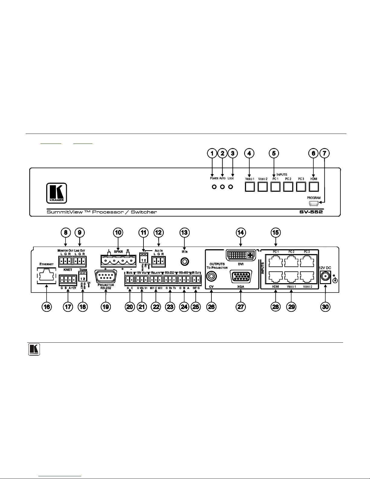
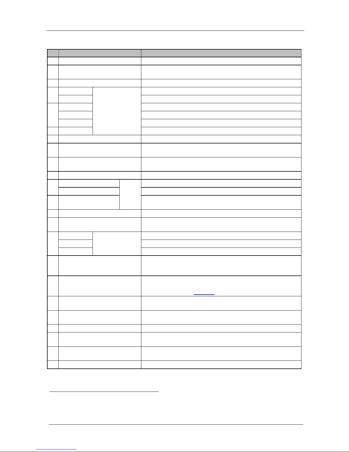
Figure 1 and Table 2 define the front and rear panels of the SV-552 SummitView™ Processor/ Switcher.
Figure 1: SV-552 SummitView™ Processor / Switcher Front and Rear Panels
Page 12
KRAMER: SIMPLE CREATIVE TECHNOLOGY
Defining the SV-552 Proc e s s or /Switche r
8
Table 2: SV-552 SummitView™ Processor/Switcher Underside Features
#
Feature
Function
1 POWER LED Lights when the unit receives power
2 AUTO LED Lights when the unit is configured to automatically identify and
select an input according to a preconfigured priority
3 LOCK LED Lights when the front panel buttons are locked
4 VIDEO 1
INPUTS Buttons
(used for testing)
Press to select the video 1 source
VIDEO 2 Press to select the video 2 source
5 PC 1 Press to select the PC 1 source
PC 2 Press to select the PC 2 source
PC 3 Press to select the PC 3 source
6 HDMI Press to select the HDMI source
7 PROGRAM USB Connector Program software - for service use only
8 MONITOR OUT Terminal Block Connect to an exter nal au dio am pl ifier. This is the same as the
audio Line Out but lacks level control
9 LINE OUT Terminal Block Connect to an external au dio am pl ifi e r. T his is the same as the
Monitor Out but with level control
10 SPKR Terminal Block Connect to the left and right speakers
11 PHANTOM DIP-switch 1
AUX IN
Configures Aux In for use with a microphone
MIC DIP-switch 2 Turns on Phantom Power 9V on the A ux In connector
12 L, G, R Terminal Block Connect to an additio nal au di o sou rce or microphone for mi xing
with the audio line level input (talk over)
13 IR IN 3.5mm Mini Connector Connect to an IR receiver
14 OUTPUTS TO PROJECTOR DVI
Connector
Connect to the D VI/HDMI input o f t he pr oje ctor
15 PC 1
INPUTS
RJ-45 Connectors
Connect to the PC 1 source
PC 2 Connect to the PC 2 source
PC 3 Connect to the PC 3 source
16 ETHERNET RJ-45 Connector Connect t o a PC runn ing t he S ite-CNTL software via the network or
Internet for contro l and conf igura t ion of the unit. Default IP settings:
Address 192.168.1.39, port 50000, subnet mask 255.255.255.0
17 K-NET1 Terminal Block Connect pin G to the Ground co nnect ion ; Conne ct pin B and pin A to
the RS-485, and pin +12V to the power adapter. For details on
connecting K-Net, see
Figure 10
18 TERM DIP-switches DIP-switches for line termination of the unit (DIP-switch 1 is for
K-Net, DIP-switch 2 is for RS-485)
19 PROJECTOR RS-232 9-pin D-sub
Connector
Connect to the projector for projector control
20 MUTE Terminal Block Mutes the audio outpu ts
21 10V VOL Terminal Block Connect to an external pot entiometer on a wall plate2 to adjust the
volume of the speakers
22 RELAYS Terminal Block Connect t o a roo m item (such a s l ightin g, scre en se tting s, bl inds , an d
so on)
23 RS-232 Terminal Block Connect to the RS-23 2 c onne ctor o n a ny s er ial contro lled d ev ice
1 K-Net is a proprietary Kramer protocol for interconnecting Kramer units
2 For example, the RC-63DL
Page 13
Defining the SV-552 Proc e s s or /Switche r
9
# Feature Function
24 RS-485 Terminal Block Connect to the RS-485 detachable terminal block on a RS-485
controlled devic e
25 IR OUT Terminal Block Control a machine via an IR Emitter
26 CV RCA
Connector
OUTPUTS
TO
PROJECTOR
Connect to the co mposite v ideo inp ut of the pro jecto r
27 XGA 15-pin HD
Connector
Connect to the co mputer gr aphic s or other display device input of the
projector
28 HDMI/DVI
INPUTS
RJ-45
Connectors
Connect to the HDMI /D VI accep tor1
29 VIDEO 1 Connect to the video 1 sour ce
VIDEO 2 Connect to the video 2 sour ce
30 12V DC +12V DC connector for powering the unit
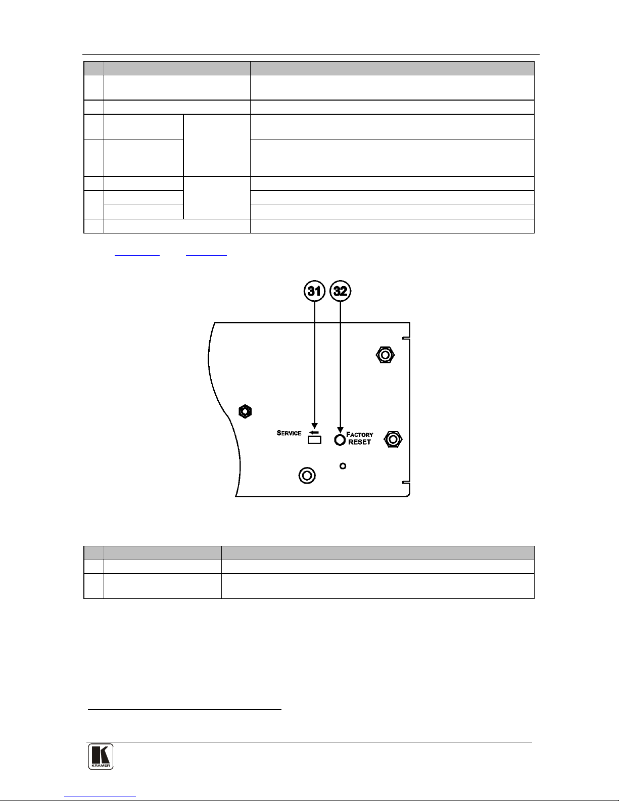
Figure 2 and Table 3 define the underside panel of the SV-552
SummitView™ Pro cessor/ Switch er.
Figure 2: SV-552 SummitView™ Processor / Switcher Underside
Table 3: SV-552 SummitView™ Processor/Switcher Underside Features
#
Feature
Function
31 SERVICE Switch For technical support use only
32 FACTORY RESET Button Press and hold while powering up the unit to reset the audio, switching
and Ethernet settings to their factory default values
4.1 DDC Support
When establishing a VGA connection between a PC or laptop and a display
device, a set of parameters known as EDID which is carried over the DDC
channel is exchanged between them. With some PC graphic cards and laptops
1 Using a DVI/HDMI adapter or the Kramer C-HDMI/DVI HDMI to DVI Single Link (18 +1 pin) cable
Page 14

KRAMER: SIMPLE CREATIVE TECHNOLOGY
Connecting the SV-552 SummitView™ Processor/ Switcher
10
this information excha nge i s e ssential for proper VGA OUT operation. Using
the Kramer Pico TOOLS™ FC-200 EDID Copier, you can copy the EDID
information from your display and upload it to the SV-301xl wall plate,
ensuring trouble-free operation of the system with any PC or Laptop.
When used in conjunc tion with the SV-301 and the SV-306, the SV-552
Processor/Switcher provides E DID PassThru. When use d in conjunction with
the SV-306, the SV-552 Processor/Switcher also provides HDCP support.
PART III Detailed Installation Instructions
PART III covers connecting the SV-552, installing the Wall Plates and the Room
Controller
We recommend that after deciding where you want to install the screen and
the projector, you install in this or der, the:
1. Cables and wires (see
Section 5.1
2. Room controller (see
).
Section 5) and wall plates (see 7Section
5 Connecting the SV-552 SummitView™ Processor/
Switcher
).
This section describes:
• Connecting the SV-552 (see Section 5.1
• Operating the SV-552 Remotely (see ) Section 5.2
• Installing the SV-552 in a 19” rack (see ) Section 5.2
5.1 Connecting the SV-552 Processor/Switcher
)
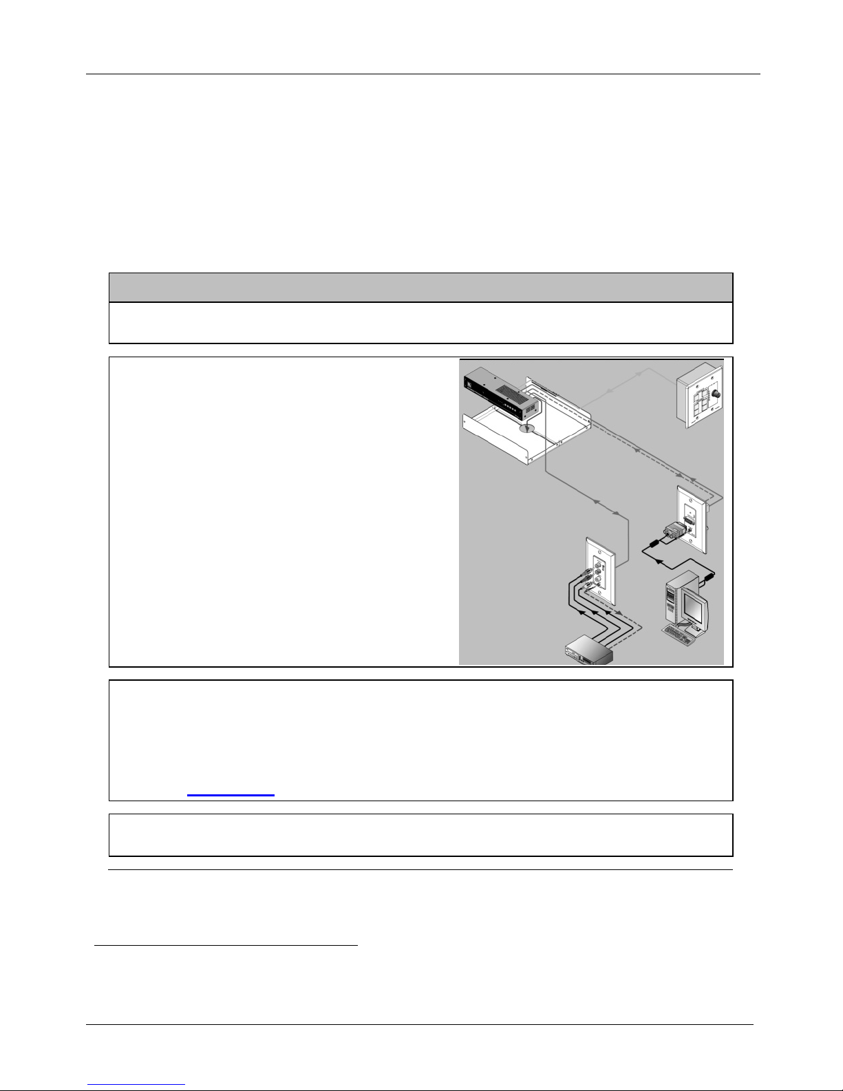
The example in
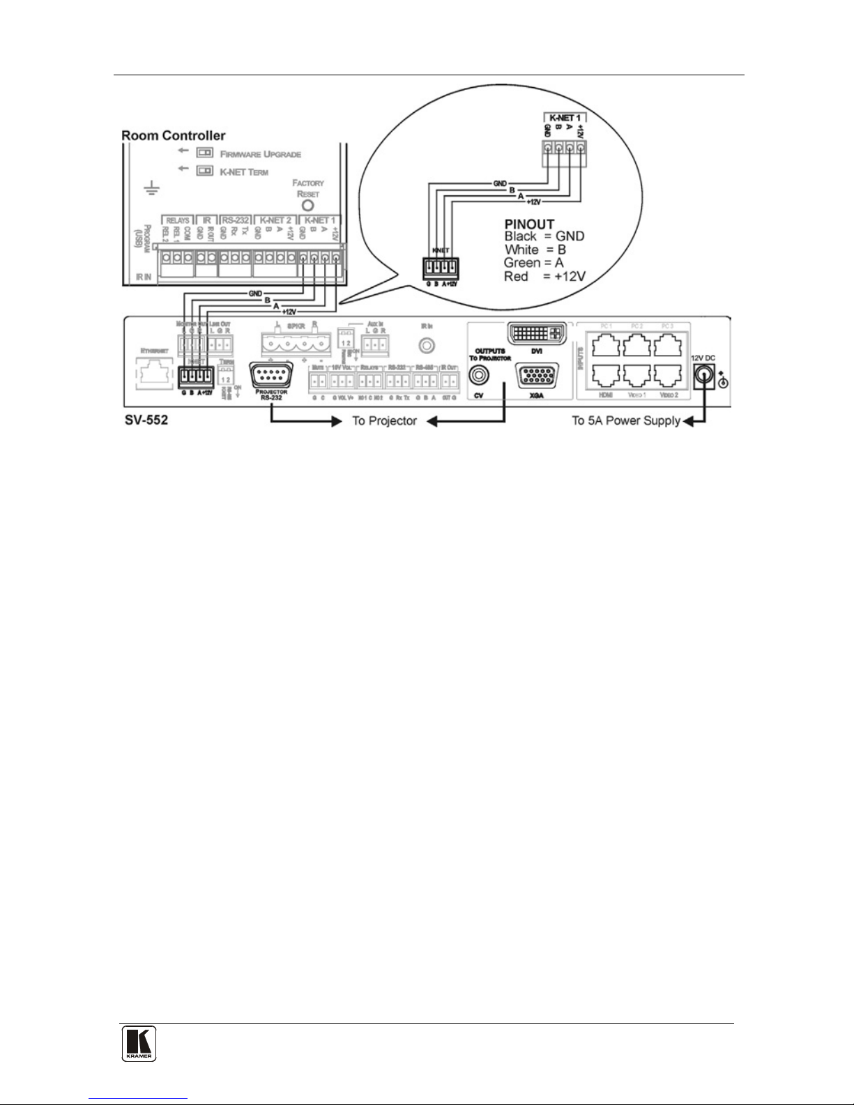
Figure 3 shows how to connect t he SV-552.
Page 15

Connecting the SV-552 SummitView™ Processor/ Switcher
11
Figure 3: Connecting the SV-552
For instructions on wiring t he K-Net connector, see Section 8.
5.2 Operating the SV-552 Processor/Switcher Remotely
The SV-552 Processor/Switcher can be operated r emotely via Ethernet over
a LAN using the Krame r Site-CTRL
™
software. For details see the
Site-CTRL and Web Access Online User Guide
1
.
1 Available from http://www.kramerelectronics.com
Page 16
KRAMER: SIMPLE CREATIVE TECHNOLOGY
Connecting the SV-552 SummitView™ Processor/ Switcher
12
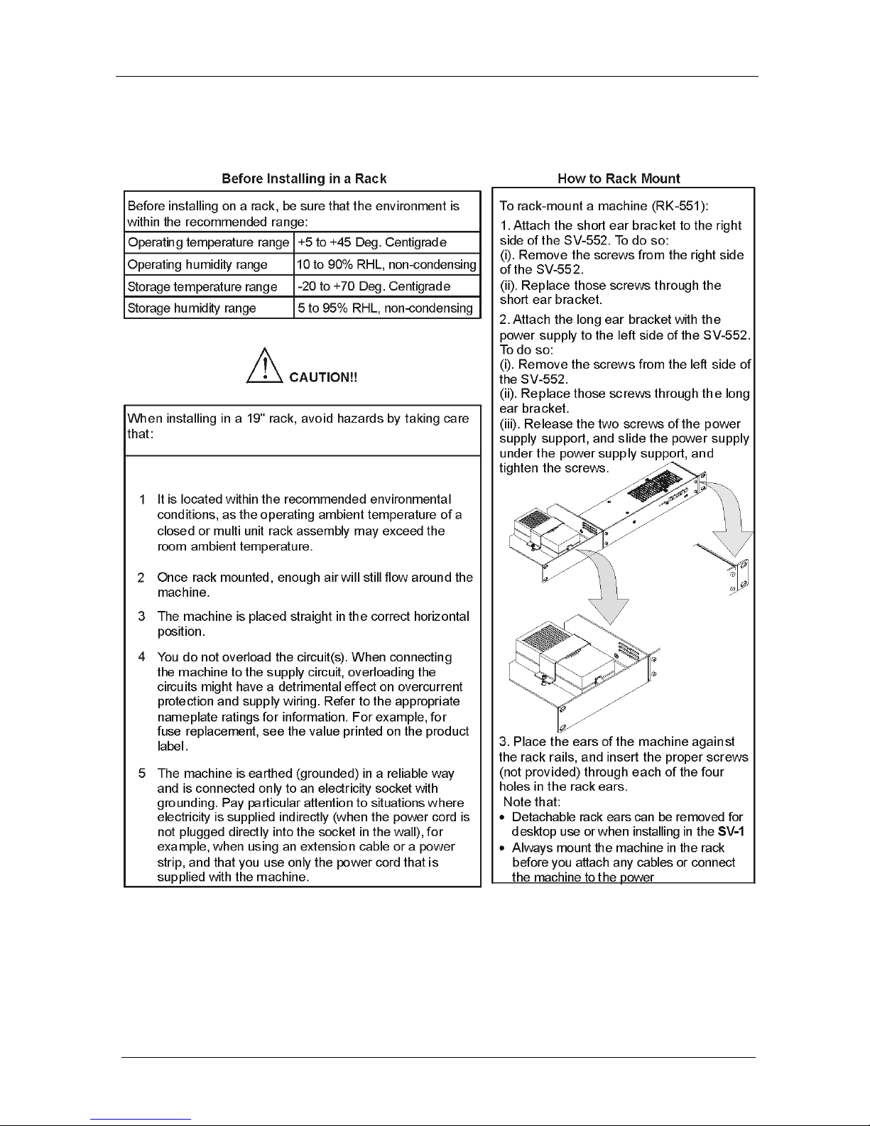
5.3 Installing the SV -552 in a 19” Rack (Optional)
This section descr ibes how to mount the SV-552 in a 1 9” rack using the
(optional) RK-551 Rack Adapt er.
Page 17

The RC-63DL Room Controller
13
6 The RC-63DL Room Controller
The RC-63DL is a room control panel that can be used independently or as a
user interface when connected to a Master Room Controller
1
for control of
A/V equipment in any room.
RC-63DL is th e recommended room controller for an SV-552 SummitView™
basic installation and is described in that user manual . The RC-63DL has an
LCD screen, letting you program the required group labels.
The Kramer RC-63DL is available as a 2 gang wall plate for either the USA
or Euro pe. It feature s 6 front pa nel buttons designed in two groups; one group
of 2 buttons, and another group of 4 buttons. Each group is user
programmable.
The RC-63DL also includes:
• A digital volume control a djustment kn ob w ith fiv e L EDs
• Two relays for the simplified and centralized control of room functions
(such as lighting, closing blinds, screen settings, and so on)
• An IR output, a bi-directional RS-232 port, and two K-Net ports
• An IR-learner for the customized control of external sources,
memorizing the IR commands from different remote transmitters
A USB port is included for programming the RC-63DL via a computer.
6.1 Defining the RC-63DL
Figure 4, Table 4, Figure 5 and Table 5 define the RC-63DL.
1 Such as the Kramer SummitView System or the SL-1 Master Room Controller
Page 18

KRAMER: SIMPLE CREATIVE TECHNOLOGY
The RC-63DL Room Controller
14
Figure 4: RC-63DL Ro om Co nt r o ll e r Front Pa nel
Table 4: RC-63DL Room Controller Front Panel Features
# Feature Function
1 SOURCE Buttons 4 configurable backlit buttons for any supported command1
2 “DISPLAY” and
“SOURCE” Labels
LCD on a blue background that displays up to 8 characters at a time (programmed
via the USB port) and includes rolling text
3 DISPLAY Buttons 2 configurable backlit buttons for any supported command
4 VOLUME LED Lights red, indicating maximum volume
5 VOLUME LEDs Lights green, indicating volume level
6 VOLUME Knob Rotate clockwise to increase the level
Version for Europe
Version for the USA
Figure 5: RC-63DL Room Controller Rear Panel
1 By the system integrator only
Page 19
The RC-63DL Room Controller
15
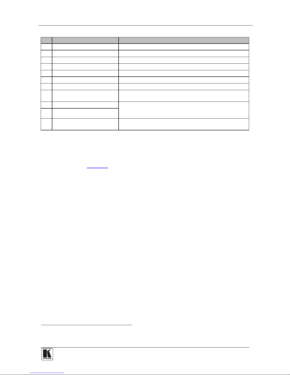
Table 5: RC-63DL Room Controller Rear Panel Features
#
Feature
Function
1 FIRMWARE UPGRADE Switch For technical support use only
2 Grounding Screw Connect to groundin g wi re
3 K-NET TERM Switch For line termination
4 PROGRAM USB Connector Connect to a computer for unit configuration
5 IR IN Receiver Receives IR remote commands
6 RELAY Connections Connect to room ite ms (such as li ghting , screen s ettin gs, and so on)
7 IR Connections Control a machine via an IR Emitter
8 RS-232 Connections Connect to the RS-232 conne ctor on the A/V equipment or a PC or
other Serial Controll er
9 K-NET 2 Connections On K-NET 1 and K-NET 2, PIN GND is for the Ground
connection
1
; PIN B (-) and PIN A (+) are for RS-485, and PIN
+12V is for powering the unit
10 K-NET 1 Connections
11 FACTORY RESET Button Press and hold while powering up the unit to reset the audio,
switching and Ethernet settings to their factory default values
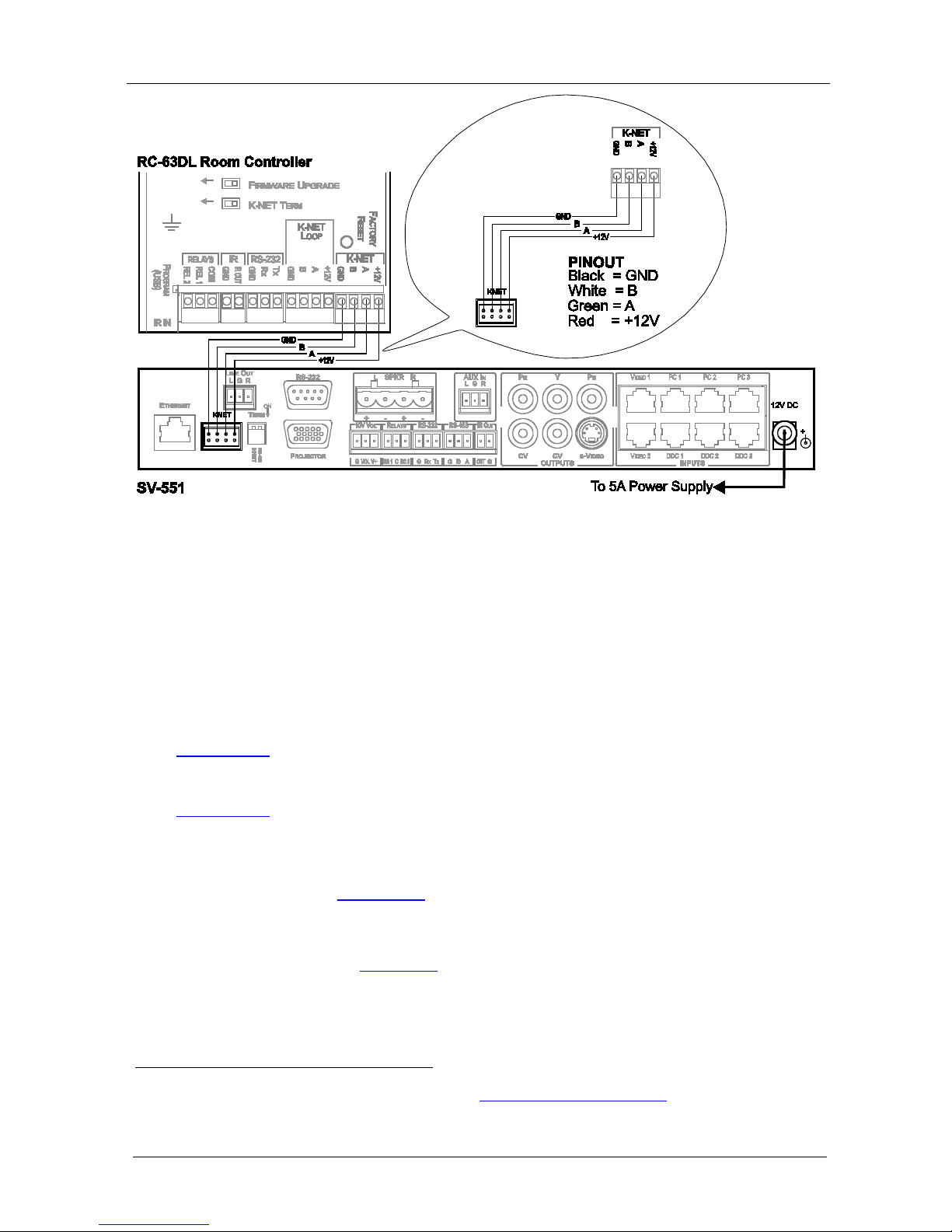
6.2 Connecting the Room C ontroller
Since the room controller is used as a slave system controller for Master
Room Controllers via the proprietary communication chan nel K-Net (as
illustrated in
Figure 6):
• It requires only a K-Net connection to the Master Room controller
• A power supply unit is not required
2
• The room controller can be programmed only via the SV-552
Processor/Switcher Master Room controller
1 The ground connection is sometimes connected to the shield of the RS-485 cable (in most applications, it is not connected)
2 Power supplies are sold separately. Consult your Kramer dealer for details
Page 20
KRAMER: SIMPLE CREATIVE TECHNOLOGY
Defining and Con necting the Wall Plates
16
Figure 6: Connecting the RC-63DL to the SV-552 SummitView™ Processor/Switcher
7 Defining and Connecting the Wall Plates
The SV-301xl and SV-302 Wall Plates are recommended as a part of a
SV-552 SummitView™ basic installation.
The SV-306 and SV-307 Wall Plates
1
are also available for a dditional
purchase (optional) and require dedicated BC-DGKat524 or BC-DGKat-623
cable.
Section 7.1 defines the SV-301xl, SV-302, SV-306 and SV-307 for the United
States.
Section 7.2
STP cabling of 15.24m (50ft) in length is available2 which is suitable for the
SV-301xl/302 (see
defines the SV-301xl, SV-302 and SV-306 for England and
Europe.
Section 11). When req uired, longe r STP cabling can be
used but we recommend a maximum transmis sion range o f 30m (100ft).
Exceeding the recommended distance may result in reduced image quali ty.
For the TP pinout see
8Section .
1 Download the user manuals for the SV-306 and SV-307 from http://www.kramerelectronics.com
2 Plenum-rated for the SummitView™ US version; non-plenum for the SummitView™ Europe
Page 21
Defining and Con necting the Wall Plates
17
Advanced User Tip
The SV-302 and SV-306 IR OUT port enables remote
IR control (this requires the appropriate programming
of the SV-552) over the source connected to it (for
example, a DVD player, a VHS player, and so on).
7.1 Defining the Wall Plates (U.S.)
This sect ion defines the U.S. v e rsion of the following wall plates:
• SV-301xl (
Section 7.1.1
• SV-302 () Section 7.1.2
• SV-306 (
)
Section 7.1.3
• SV-307 () Section 7.1.4
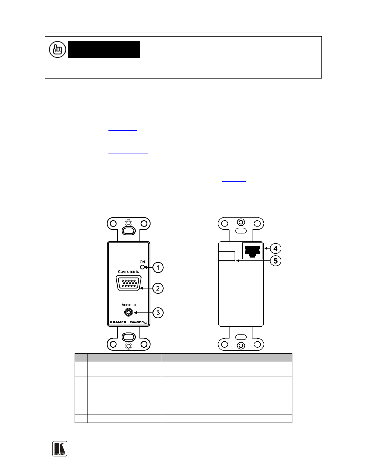
7.1.1 Defining the SV-301xl (U.S.)
)
The SV-301xl is a sin gle-gang wall plate insert.
Table 6 defines the front and
rear views of the SV-301xl.
Table 6: Defining the SV-301xl (U.S.)
SV-301xl Front View
SV-301xl Rear View
#
Feature
Function
1 ON LED Lights red w hen r ecei ving power (w hen no s ignal is
detected); lig hts gr een w hen r ecei ving a s ignal
2 COMPUTER IN 15-pin HD
Connector
Connect to the co mputer gr aphic s sour ce
3 AUDIO IN 3.5mm Mini
Connector
Connect to the unba lanced s tereo a udio sou rce
4 RJ-45 connector
Connect to the SV-552 Processor/Switcher
5 DC IN Power Connec tor Connect to a 12V power supply
Page 22
KRAMER: SIMPLE CREATIVE TECHNOLOGY
Defining and Con necting the Wall Plates
18
EDID information can be sto r e d in the wall plate by using the FC-200 XGA
EDID Copier Kramer Tool (see the FC-200 XGA EDID Copier User
Manual).
Table 7
defines the SV-301xl, as an example, in its plastic frame.
Table 7: Enclosing a Wall Plate (U.S.) in its Plastic Frame1
1 Each model that is designed specifically for the U.S. market can be fitted inside a plastic frame
Page 23
Defining and Con necting the Wall Plates
19
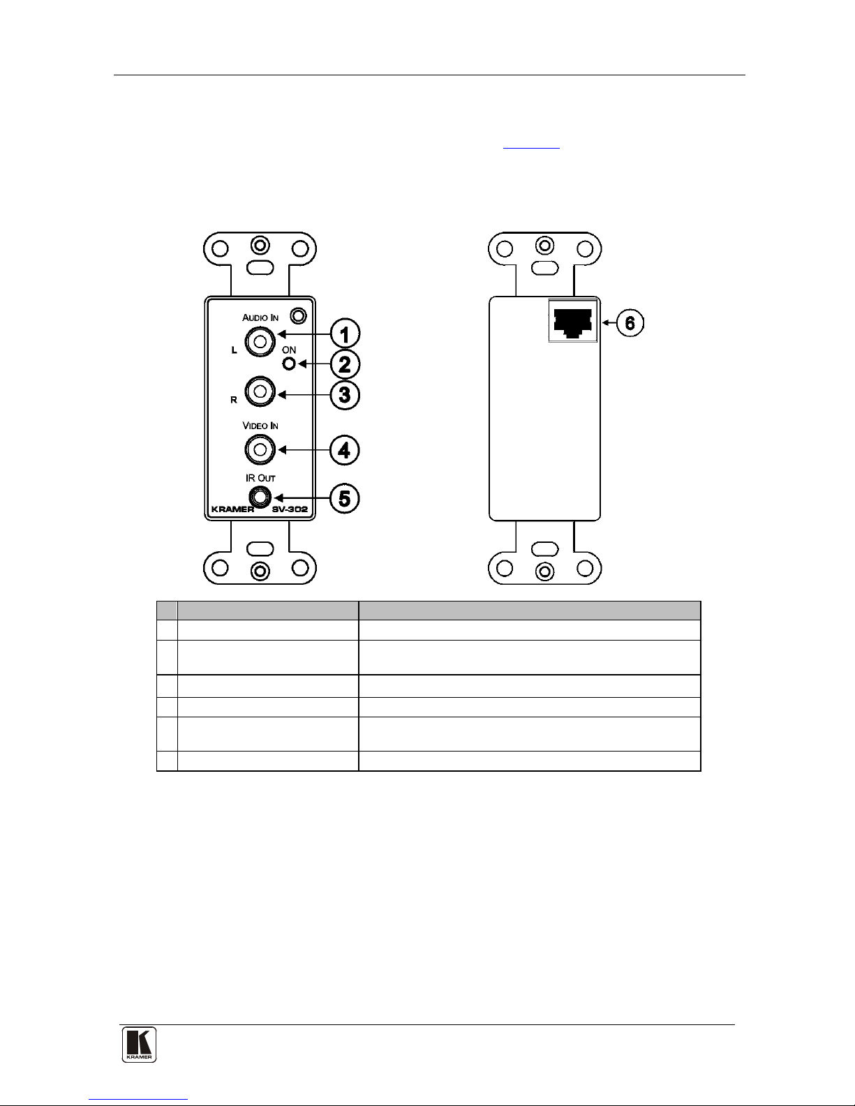
7.1.2 Defining the SV-302 (U.S.)
The SV-302 is a single-gang wall plate insert. Table 8 defines the front and
rear views of the SV-302.
Table 8: Defining the SV-302 (U.S.)
SV-302 Front View SV-302 Rear View
#
Feature
Function
1 L AUDIO IN RCA Connector Connect to the left analog audio source
2 ON LED Lights red when receiving power (when no signal is
detected); lights green when receiving a signal
3 R AUDIO IN RCA Connector Connect to the right analog audio source
4 VIDEO IN RCA Connector Connect to the co mposite v ideo sour ce
5 IR OUT 3. 5m m Mini
Connector
Connect to a machine via an IR Emitter
6 RJ-45 connector
Connect to the SV-552 Processor/Switcher
Page 24
KRAMER: SIMPLE CREATIVE TECHNOLOGY
Defining and Con necting the Wall Plates
20
7.1.3 Defining the SV-306 (U.S.)
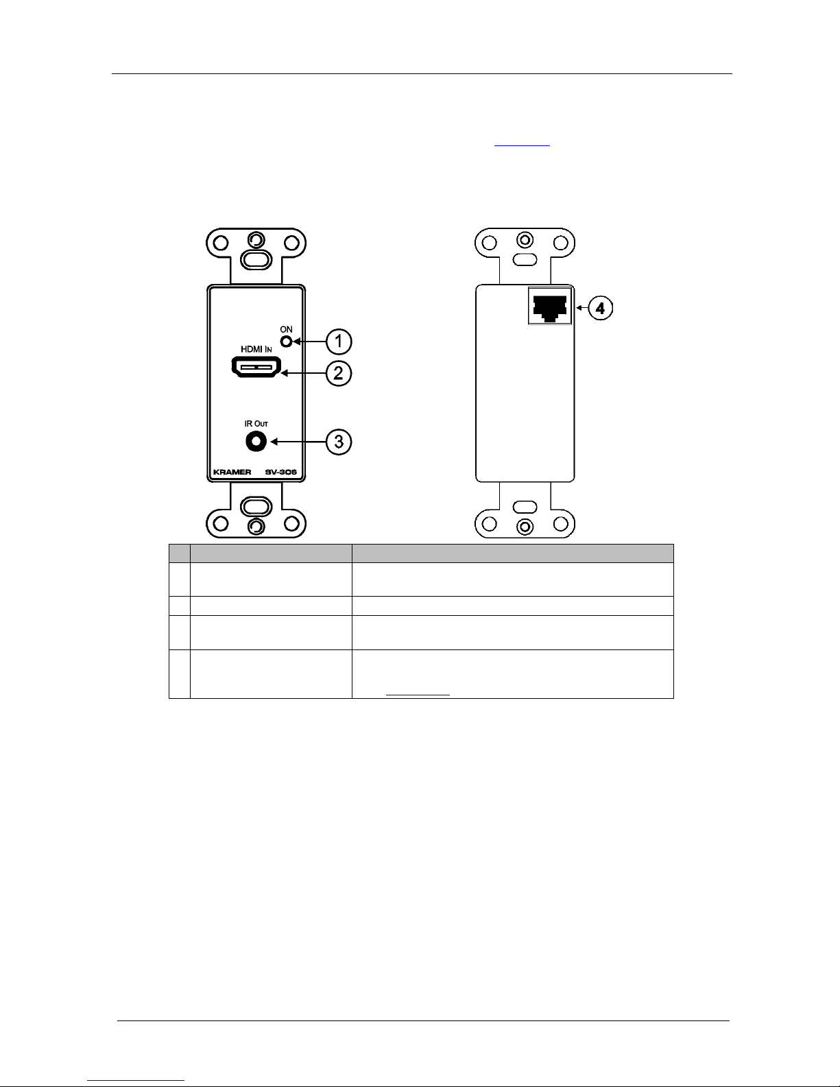
The SV-306 is a single-gang wall plate insert. Table 9 defines the front and
rear views of the SV-306.
Table 9: Defining the SV-306 (U.S.)
SV-306 Front View SV-306 Rear View
#
Feature
Function
1 ON LED Lights red w hen re ceiv ing pow er (when no s ignal i s
detected); lig hts gr een w hen r ecei ving a s ignal
2 HDMI IN Connector Connect to the HDMI digital sour ce
3 IR OUT 3.5mm Mini
Connector
Connect to a machi ne via a n IR Emi tter
4 RJ-45 connector
Connect to the SV-552. Note that the SV-306 requires
BC-DGKat524 or BC-DGKat-623 cable for connection
(see
USection 8.3U)
The SV-306 provides EDID PassThru (passes EDID signals from source to
display) and HDCP support.
Page 25
Defining and Con necting the Wall Plates
21
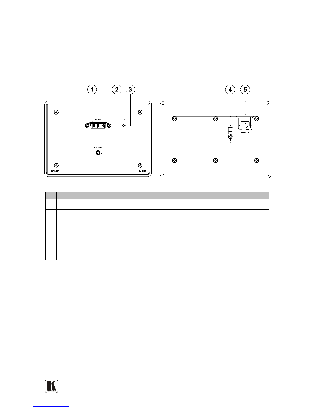
7.1.4 Defining the SV-307 (U.S.)
The SV307 is a triple-gang wall plate. Table 10 defines the front and rear
views of the SV-307.
Table 10: De fi ni ng t he SV -307 (U.S.)
SV-307 Front View SV-307 Rear View
#
Feature
Function
1 DVI IN Connector Connect to the DVI source
2 AUDIO IN 3.5mm Mini
Connector
Connect to the unbalanced stereo audio source
3 ON LED Lights red when receiving power (when no signal is detected); lights
green when receivi n g a signal
4 Ground C onne ction Ring tongue terminal and grounding screw
5 LINE OUT RJ-45
Connector
Connect to the SV-552. Note that the SV-307 requires BC-DGKat524
or BC-DGKat-623 cable for connection (see
USection 8.3U)
Page 26

KRAMER: SIMPLE CREATIVE TECHNOLOGY
Defining and Con necting the Wall Plates
22
7.2 Defining the Wall Plates (England and Europe1)
This sect ion defines the England and European version of the fol l owing wall
plates:
• SV-301xl (
Section 7.2.1
• SV-302 () Section 7.2.2
• SV-306 () Section 7.2.3
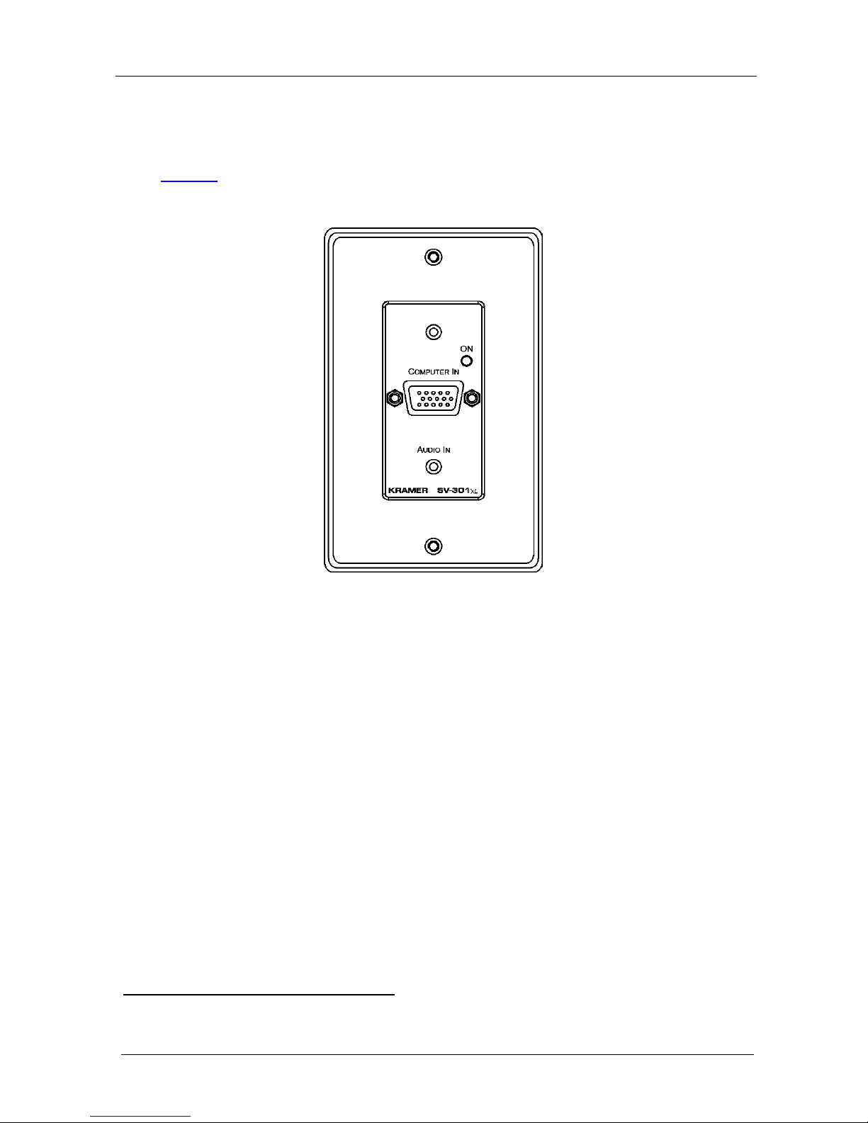
7.2.1 Defining the SV-301xl (England and Europe)
)
The SV-301xl is a sin gle-gang wall plate. The SV-301xl has a terminal block
at the rear.
Table 11 defines the front and rear views of the SV-301xl.
Table 11: Defining the SV -301xl (Engl an d an d Europe)2
SV-301xl Front View SV-301xl Rear View3
#
Feature Function
1 ON LED
Lights red when re ceiv ing pow er (w hen no s ign al i s dete ct ed) ;
lights green w hen recei ving a signa l
2 COMPUTER IN 15-pin HD
Connector
Connect to the computer gr aph ics source
3 AUDIO IN 3.5mm Mini
Connector
Connect to the unba lan ced s tere o a udio sou rce
4 Terminal Block
Connect to SV-552 u sing STP cabl ing (see
Section 8.15 )
GROUND Connection Ring tongue terminal and grounding screw
1 The European versions are equipped with easy terminals, see Section 8.2
2 When mounting in Belgium and Germany, use the standard WP Adapter
3 Some models may have a DC IN connector for connecting to a 12V DC power supply
Page 27

Defining and Con necting the Wall Plates
23
EDID information can be sto r e d in the wall plate by using the FC-200 XGA
EDID Copier Kramer Tool (see the FC-200 XGA EDID Copier User
Manual).
7.2.2 Defining the SV-302 (England and Europe)
The SV-302 is a single-gang wall plate and has a terminal block at the
rear.
Table 12 defines the front and rear views of the SV-302.
Table 12: De fi ni ng t he SV -302 (England and Europe)1
SV-302 Front View SV-302 Rear View
# Feature Function
1 ON LED Lights red when re cei ving power (w hen no sign al i s
detected); lig hts gr een w hen r ecei ving a s ignal
2 L AUDIO IN RCA Connector Connect to the le ft ana log au dio s our ce
3 R AUDIO IN RCA Connecto r Connect to the right analog au dio s our ce
4 VIDEO IN RCA Connector Connect to the co mposite v ideo sour ce
5 IR OUT 3.5mm Mini Connector Conne ct t o a machine via a n I R Emi tter
6 Terminal Block
Connect to SV-552 u sing STP cabl ing (see
Section 8.1 )
1 When mounting in Belgium and Germany, use the standard WP Adapter
Page 28

KRAMER: SIMPLE CREATIVE TECHNOLOGY
Defining and Con necting the Wall Plates
24
7.2.3 Defining the SV-306 (England and Europe)
The SV-306 is a single-gang wall plate and has a terminal block at the
rear.
Table 13 defines the front and rear views of the SV-306.
Table 13: De fi ni ng t he SV -306 (England and Europe)1
SV-306 Front View
SV-306 Rear View
#
Feature
Function
1 ON LED Lights red when re ceiv ing pow er (w hen no s ign al i s dete ct ed) ; light s
green when rece iving a s ig nal
2 HDMI IN Connector Connect to the HDMI digital source
3 IR OUT 3.5mm Mini
Connector
Connect to a machi ne via a n IR Emi tter
4 Terminal Block
Connect to SV-552. Note that the SV-306 requires BC-DGKat524 or
BC-DGKat-623 cable for connection
5 GROUND Connection Ring tongue terminal and grounding screw
6 GND +12V Terminal Block Connect t o an op tiona l 12 V power supp ly
The SV-306 provides EDID PassThru (passes EDID signals from source to
display) and HDCP s upport.
1 When mounting in Belgium and Germany, use the standard WP Adapter
Page 29

Defining and Connecting the Wall Plates
25
7.3 Connecting the Wall Plates to the SV-552
The wall plates are connected to the corresponding inputs on the SV-552
using the supplied
1
STP or optional BC-DGKat524 or BC-DGKat-623
cables (SV-306/307, see
Section 8.3
). The SV-301xl and the SV-302 U.S.
versions have RJ-45 CAT 5 connectors on the rear, as defined in
Table 14.
The SV-301xl and the SV-302 European versions have terminal blocks on the
rear, as defined in
Table 11 and Table 12 respectively.
The diagrams below show both U.S. and European versions for illustration
purposes only.
7.3.1 Connecting the SV-301xl Wall Plate to the SV-552
To connect the SV-301xl as the example i n Figure 7 illustrates (see also the
separate color illustratio n in
Section 5.1):
Figure 7: Connecting the SV-301xl to the SV-552
1. Connect the computer graphics source (for example, a laptop) to the
Computer In 15-pin HD connector and to the unbalanced stereo Audio In
3.5mm mini jack on the front of the SV-301xl, for example, using a
1 There are two types of STP cable provided with SummitView™: CP-STP-50 (plenum-rated for the SummitView™ US) or
C-STP-50 (non-plenum for the SummitView™ Europe). Other STP cables can also be used. However, when using longer
STP cables, image quality may be impaired
Page 30

KRAMER: SIMPLE CREATIVE TECHNOLOGY
Defining and Con necting the Wall Plates
26
Kramer C-GMA/GMA cable (VGA HD15M +Audio connector to VGA
HD15M +Audio connector)
1
.
2. On the rear of the SV-301xl, connect the RJ-45 CAT 5 connector using
either the RJ-45 connector (U.S. vers ion) or terminal block (European
version) to either of the PC 1, PC 2, or PC 3 inputs.
7.3.2 Connecting the SV-302 Wall Plate to the SV-552
To connect the SV-302 as the ex am pl e in Figure 8
illustrates (see also the
separate color illustratio n in
Section 5.1):
Figure 8: Connecting the SV-302 to the SV-552
1. On the front of the SV-302, connect the:
Composite video source (for example, a DVD
player) to the yellow RCA connector, and to the
unbalanced stereo audio RCA connectors
IR OUT 3.5mm mini connector via an IR Emitter2
Control cable directly onto the IR sensor window of
the controlled device (for example, a DVD player)
1 Not supplied. The complete list of Kramer cables is available from http://www.kramerelectronics.com
2 The Emitter contains a small infrared LED housed in a miniature, mouse shaped, black plastic shell. It emits visible red light
in addition to IR (infrared) control signals when activated by IR commands sent to it by IR receivers or other controllers. The
Emitter Control Cable comes with a clear adh esive film included o n the emitter housin g for attachment to the IR window of
the controlled component and pieces of double-sided clear adhesive tape included for replacement purposes
Page 31

Defining and Con necting the Wall Plates
27
2. On the rear of the SV-302, connect the RJ-45 CAT 5 connector to either
input VIDEO 1 or VIDEO 2 input on the SV-552.
7.3.3 Connecting the SV-306 Wall Plate to the SV-552 (Optional)
In addition, using BC-DGKat524 or BC-DGKat-623 cable as shown
in
Figure 9, you can connect the:
• SV-306 which accepts an HDMI source and connects to the HDMI
input on the rear of the SV-552. The input signals are converted via an
RJ-45 CAT 5 connector at the rear, and transmitted to the SV-552. The
SV-306 also has an IR out 3.5mm mini connector (connection to the
SV-552 is sim ilar to th e SV-302)
• SV-307 which accepts a DVI component video source on three RCA
connectors, as well as a digital audio (S/PDIF) input on an RCA
connector, and connects to the HDMI input on the rear of the SV-552.
The input signals are converted via an RJ-45 CAT 5 connector at the
rear and transmitted to the SV-552.
Figure 9: Connecting the SV-306/307 to the SV-552
Page 32

KRAMER: SIMPLE CREATIVE TECHNOLOGY
Wiring the TP Line In/Line Out Connectors
28
8 Wiring the TP Line In/Line Out Connectors
STP cabling1 with a length of 15.2m (50ft) in length is available for use with
the Kramer A/V SummitView™ systems for c onnecting to the SV-301xl/302
Wall Plates. When required, longer STP cabling can be used when purcha s ed
for standalone wall plates but we recommend a maximum transmi s sion range
of 30m (100ft). Exceeding the recommended distance may result in reduced
image qua lity.
Connecting the SV-306/307 requires BC-DGKat524 or BC-DGKat-623
cable (see
Section 8.3
This section describes how to connect the rear panel for the:
).
• US wall plate versions (see
Section 8.1
• European wall plate versions (see ) Section 8.2 )
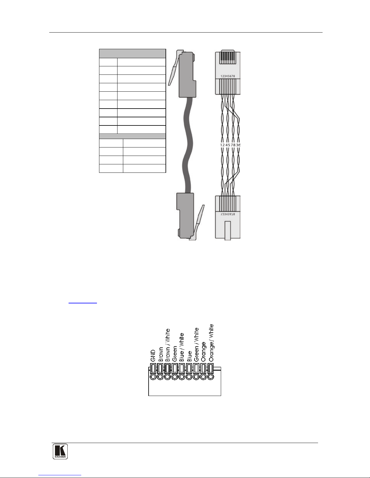
8.1 Wiring the Twisted Pair RJ-45 Terminals (U.S.)
The U.S. versions of the wall plates are equipped with RJ-45 terminals.
Table 14 defines the TP pinout, using a straight pin to pin cable with RJ-45
connectors. When using STP cable, connect/solder the cable shield to the RJ-45
connector shield.
1 Plenum-rated for the SummitView™ US version; non-plenum for the SummitView™ Europe
Page 33
Wiring the TP Line In/Line Out Connectors
29
Table 14: UTP Pinout (U.S.)
EIA /TIA 568B
PIN
Wire Color
1 Orange/White
2 Orange
3 Green/White
4 Blue
5 Blue/White
6 Green
7 Brown/White
8 Brown
Pair 1 4 and 5
Pair 2 1 and 2
Pair 3 3 and 6
Pair 4 7 and 8
8.2 Wiring the Terminal Block (England and Europe)
The European versions of the wall plates are equipped with an easy plug-in
terminal block for the STP cables. Use the color coded sticker on these
terminals for proper connection of the STP cable.
Table 15 defines the pinout for the termi nal block.
Table 15: Terminal Block Pinout (England and Europe)
Notes:
• Use the connector clips when removing the wires, not when in sert ing
them
Page 34
KRAMER: SIMPLE CREATIVE TECHNOLOGY
Grounding the Wall Plate
30
• Each wire pr ot rudes 9mm in len gth from the pl asti c in sulat ion so th at it
can be easily connected. To prevent the wires crossing, be sure that each
wire is com plet ely in se rted
• With STP cable, the GND pin is used for shi elding . Shie lding is not
needed, but if desired, connect to the GND pin of the PC
8.3 Cabling for the SV-306 and SV-307
Kramer engineers have developed special twisted pair cables to best match
our digital twisted pair products; the Kramer BCP-DGKat524 (CAT 5 24
AWG), and the Kramer BCP-DGKat623 (CAT 6 23 AWG cable). These
specially built cables sig nificantly outperform regular CAT 5/CAT 6 cables.
A system range of up to 90m (295ft) at 1080i/SXGA, or up to 30m (98ft) at
1080p/UXGA on shielded BCP-DGKat524 cable; 90m (295ft) at 1080i, or
up to 70m (230ft) at 1080p/UXGA on shielded BCP-DGKat623 cable.
Note that the STP cable Ground shield must be connected/soldered to the
connector shield.
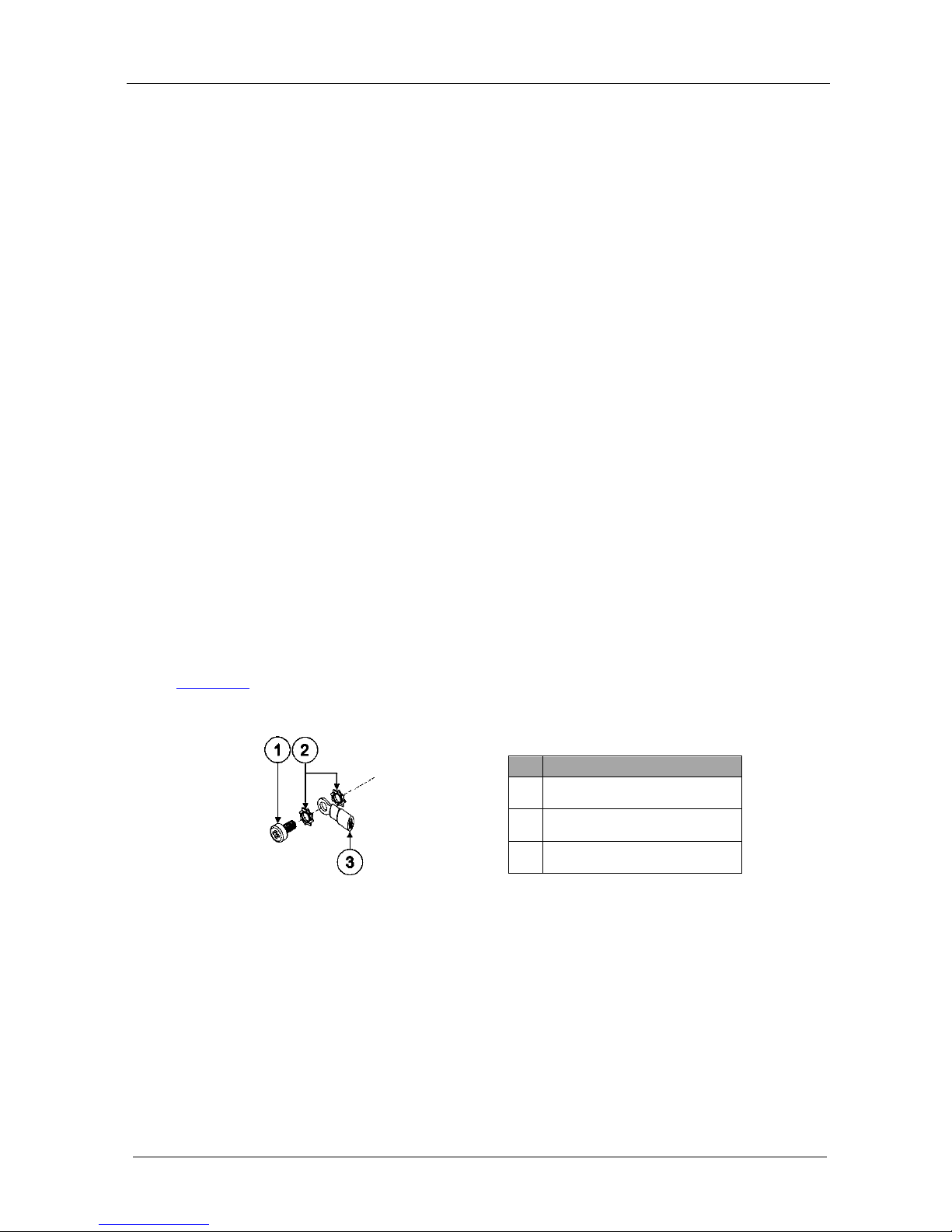
9 Grounding the Wall Plate
The gro unding scre w is used to earth the cha s s is of the uni t to the gro und of
the building, thus preventing static electricity from interfering with the
product’s performance.
Table 15 defines the groundi ng screw components.
Table 16: Grounding Screw, Lock Washers and Ring Tongue Terminal
# Item
1 M3X6 s crew
2 1/8" Toothed Lock Washer
3 M3 Ring Tongue Terminal
To ground a wall plate:
1. Connect the Ring Tongue terminal to the building grounding point wire
(it is recommended to use a green-yellow AWG#18 wire, crimped with a
proper hand-tool).
2. Insert the M3x6 screw through the toothed lo ck washer s and the tongue
terminal in the order shown ab ove.
3. Insert the M3x6 screw (with the two toothed lock washers and ring
tongue terminal) into the grounding screw hole and t ighten the s crew.
Wiring t he K-Net™ Connector:
Page 35
Grounding the Wall Plate
31
Figure 10: Wiring the K-Net Connector
Page 36
KRAMER: SIMPLE CREATIVE TECHNOLOGY
Customizing the Controllers' Buttons and Labels
32
PART I V Further information
PART IV includes further information
10 Cust omizing the Controllers' Buttons and Labels
This section describes the backlit buttons and the button labels sheet.
10.1 Backlit Buttons
The RC-63DL backlit b uttons
1
have plastic caps. To insert a label on a button
(we recommend doing this be f ore installing the controller as it in volves
removing the front plate), unscr ew the front p late attach ment screws using a
screwdriver, gently remove t he transparent button cap with yo ur fingers, and
insert the label under the button cap. Replace the button cap with the label
onto the button base .
10.2 Button Label Sheet
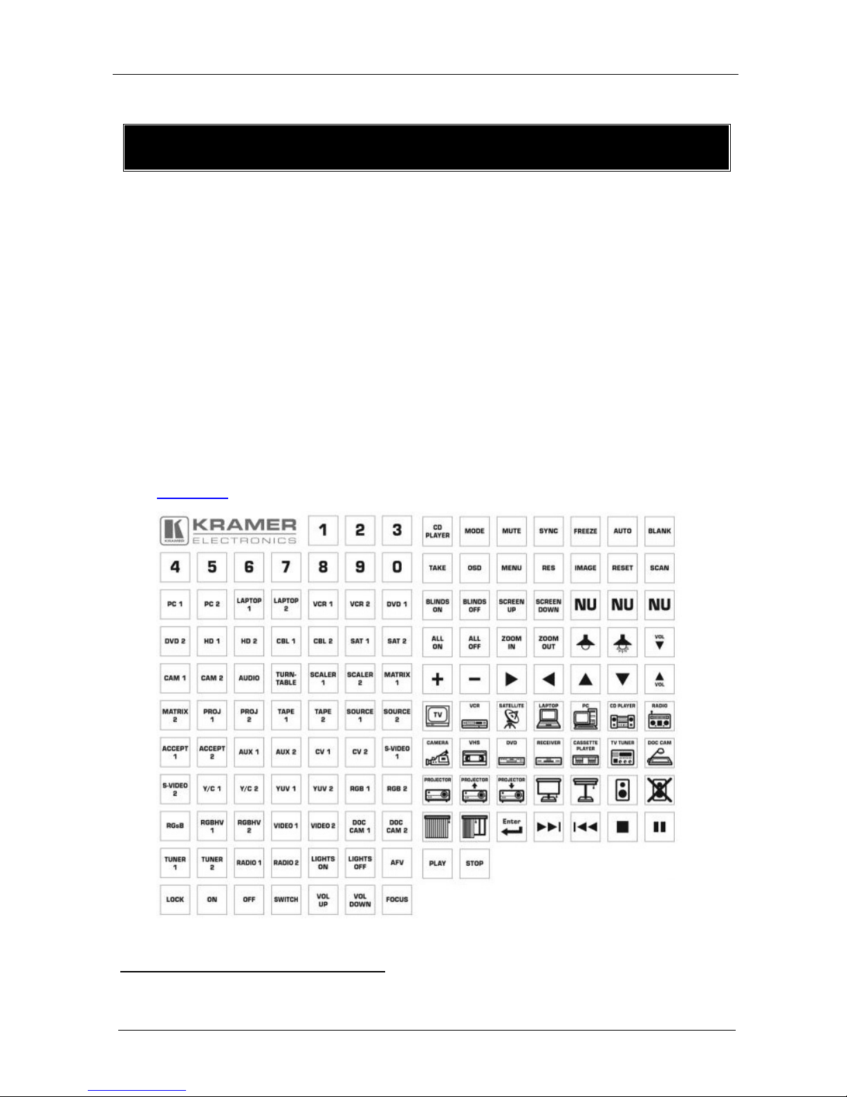
Figure 11 illustrates the sample Button Label sheet.
Figure 11: Sample Button Labels Sheet
1 You can program the color of the button with flexible RGB values
Page 37
SummitView™ System Cables
33
11 Summ it Vi ew™ System Cables
Table 17 defines the recommended cables for a SummitView™ installation.
Table 17: Recommended Cables for use with SummitView™ Systems
Item Description Supplied with
the SV552 ALC
Cable for use with the SV-301xl
CP-STP-50/C-STP-50
(1 cable
1)2
STP cable 15.2m (50ft) from SV-301 to SV-552
-
Cable for use with the SV-302
CP-STP-50/C-STP-50
(1 cable
1)2
STP cable 15.2m (50ft) from SV-302 to SV-552
-
Cables for use with the SV-552
P.S 12V/5A DESKTOP with
DC plug
(1 cable)
1
POWER CORD 110V
(1 cable)
1
C-MGM/MGM-3 (1 cable)3
Molded Micro VG A to VG A cab le 0.91 m (3ft),
from SV-552 to the d isp lay devic e
1
C-RVM/RVM-3 (1 c able)3
Molded RCA RG-59 video cable 0.91m (3ft),
from SV-552 to the display dev ice
1
C-HM/DM-3
HDMI to DVI cab le 0,91 m (3ft), from the SV-552
to the display device
1
C-D9M/D9F-3 (1 cable)
RS-232 cable 0.91m (3ft), fro m the SV-552 to
the display device
1
C-D9M/D9F-3 RS-232 Gender cha nger 1
BCP-2S-25 (2 cables)
Speaker cables , fro m the SV-552 to t he
speakers
-
C-UA/MUB-3 (1 cable)
USBA to Mini USB cable 0.91m (3ft), for
configuring the SV-552 or the RC-63DL
1
Cable for use with the RC-63DL or other controller
BCP-KNET-50 (1 cable)
Balanced Stereo Audio/Contr ol ca ble 15.2m
(50ft), from the RC-63DL to the SV-552
1
1 There are two types of STP cable provided with SummitView™ : CP -STP-50 (plenum-rated for the SummitView™ U.S.) or
C-STP-50 (non-plenum for the SummitView™ Europe)
2 Connect the wall plate to the SV-552
3 Connects the SV-552 to the projector
Page 38
KRAMER: SIMPLE CREATIVE TECHNOLOGY
SummitView™ Cable Termination
34
12 Summ it Vi ew™ Cable Termination
Table 18 defines the SummitView™ cable termination (connector-to-cable).
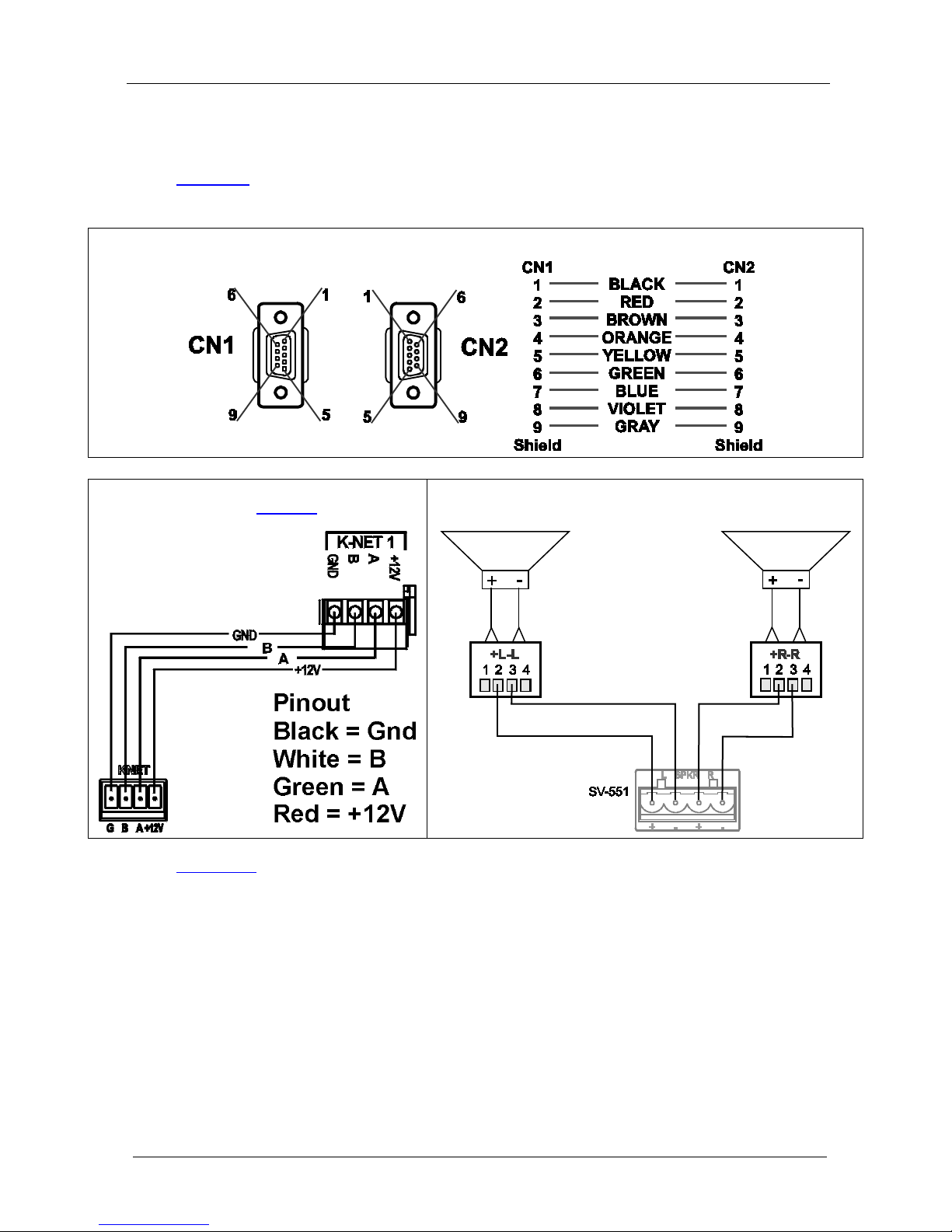
Table 18: SummitView™ Cable Termination
C-D9M/D9F-3 RS-232 Cable PINOUT
BCP-KNET-50 Cable Pinout
(see also
Figure 10)
BCP-2S-25 Cable
Figure 12 defines the stickers affixed to the SummitView™ cables.
Page 39

SummitView™ Cable Termination
35
Figure 12: Stickers Affixed to Cables
Page 40
KRAMER: SIMPLE CREATIVE TECHNOLOGY
Technical Specifications
36
13 Technical Specifi cations
Technical specifications of the SV-552 SummitView™ Processor/Switcher
are sho wn in
Table 19.
Table 19: Technical Specifications1 of the SV-552 Processor/Switcher
Item
Description
INPUTS: 1 AUX stereo on a 3-PIN terminal block; 1 HDMI, 3 PC (XGA and Y, Pb,
Pr), 1 Composite Video on RJ-45 connectors
OUTPUTS: 1 SPKR (speaker) stereo on a 4-PIN terminal block; 1 Projector (XGA) on a
15-pin HD computer graphics video connector; 1 composite video on RCA
connector; 1 DVI, 3 DDC (bi-directional, inputs/outputs, as required) on RJ45 connectors
10V Volume, 2 relays on termina l block connectors (36VAC or DC, 2A, 60VAC
maximum on non-indu ctive load) , RS-232, and RS-485 3-PIN terminal blocks;
IR OUT 2-PIN terminal block
MAX. OUTPUT LEVEL: VIDEO: CV 2.6Vp p; XGA 2.2Vpp AUDIO: 7W per channel into 4Ω
LINEOUT: 5.8Vpp @ m a x volum e, to ne
controls zeroed
BANDWIDTH (-3dB): VIDEO: CV 68MHz; XG A and Y,
Pb, Pr 130MHz
AUDIO: 20Hz to 20kHz
DIFF. GAIN: 0.35%
DIFF. PHASE: 0.01Deg.
K-FACTOR: <0.05%
S/N RATIO: VIDEO: 59dB unweighted,
66dB @5MHz weighted
AUDIO: 55dB @1KHz,
LINEOUT: 85dB @1KHz
CONTROLS: IR, RS-232, RS-485, Ethernet, K-Net
COUPLING: VIDEO: DC AUDIO/LINEOUT: Input: AC; Output: DC
AUDIO THD + NOISE: AUDIO: 1.1% @1KHz, 12.8Vpp, LINEOUT: 0.063% @1KHz 2.4Vpp
AUDIO 2nd HARMONIC: AUDIO: 0.4% @1KHz, 8Vpp, LINEOUT: 0.02% @1KHZ, 2.4Vpp
AUDIO INPUT SENSITIVITY: 140mVpp
AUDIO VOLTAGE GAIN: 97 x 39.7dB
OPERATING
TEMPERATURE:
0° to +55°C (32 ° t o 1 31°F)
STORAGE
TEMPERATURE:
–45° to +72°C (–49° to 162 °F)
HUMIDITY: 10% to 90%, RHL non-condensing
POWER CONSUMPTION: 12V 4.3A
DIMENSIONS: 27.78cm x 7.65cm x 4.36c m (10. 94" x 3.01" 1.72") W, D, H
WEIGHT: 0.65kg (1.43lbs) approx.
ACCESSORIES: See Table 17
OPTIONS: Power supply, a pair of detachable rack ears and shelf, RC-4 Infrared
Remote Controll er , RK-551 (for installing in a 19” rack)
1 Specifications are subject to change without notice
Page 41
ADA Requirements
37
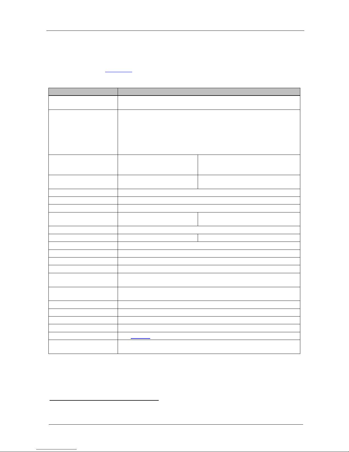
14 AD A Requirements
When not mounting the SV-552 in a rack, attention must be paid to overhead
clearances. Refer to the ADA Standards for Accessible Design (courtesy of
the U.S. Department of Justice)
1
, and in particular, section 4 -4", "Head
Room":
Figure 13: Overhead and Side Clearance Requi r em ents
1 You can download the file from their Web site at http://www.ada.gov/stdspdf.htm
Page 42

KRAMER: SIMPLE CREATIVE TECHNOLOGY
ADA Requirements
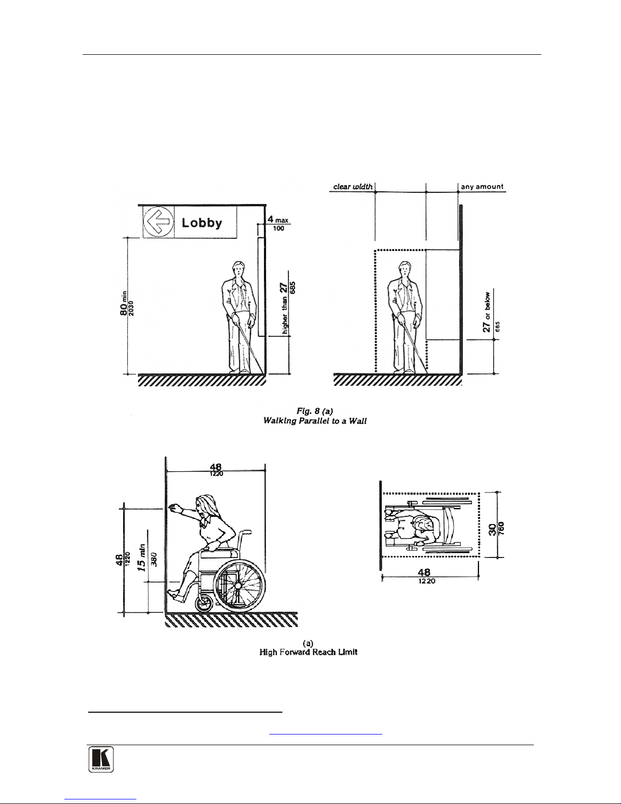
38
Figure 14: High/Low Forward, Side and Over Obstruction Reach Limit Requirements
Page 43

SV-552 SummitView™ Essentials Basic System Check List
39
15 SV-552 SummitView™ Essentials Basic System Check List
Remove this list from the user manual a nd use it to check that all components
are present.
Table 20: SV-552 SummitVi e w ™ Basic System Ch eck List
PART DESCRIPTION #
SV-552 SummitView™ Processor/Switcher
1
C-D9M/D9F-3 RS-232 cable 0.91 (3ft)
1
BCP-2S-25 Speaker cab le
2
BCP-KNET-50 Balanced Audio/Control cable 15.2m (50ft)
1
C-UA/MUB-3 USB A to mini USB B cable 0.91m (3ft)
1
P .S 12V/ 5A US and EU models
1
POWER CORD According to country
1
CD-ROM K-Config Configuration software
1
SCREWDRIVER For installation
1
RC-63DL Room Controller
1
C-UA/MUB-3 USB A to mini USB B cable 0.91m (3ft)
1
CD-ROM RC Configuration software
1
SV-301xl Wall Plate (Computer Graphics Video + Audio)
1
C(P)-STP-501 STP cable 15.2m (50ft)
1
C-MGM/MGM-3 Molded Micro VGA to VGA cable 0.91m (3ft)
1
SV-302 Wall Plate (Composite Video + Audio)
1
C(P)-STP-501 STP cable 15.2m (50ft)
1
C-RVM/RVM-3 Molded RCA RG-59 video cable 0.91m (3ft)
1
1 CP-STP-50 is plenum-rated for the SummitView™ U.S.; C-STP-50 is non-plenum for the SummitView™ Europe
Page 44

Page 45

Kramer Electronics, Ltd.
Web site: www.kramerelectronics.com
E-mail: info@kramerel. com
P/N: 2900-000603 REV 3
For the latest information on our products and a list of Kramer
distributors, visit our Web site
www.kramerelectronics.com
where updates to this user manual may be found.
We welcome your questions, commen ts and feedba ck .
Safety Warning:
Disconnect the unit from the power supply before
opening/servicing.
Caution
P/N:
2900-000603
Rev:
3
 Loading...