

Page 1

Kramer Electronics, Ltd.
USER MANUAL
Models:
SPK-CC678, Closed-back Ceiling Speakers
SPK-CCV448, Closed-back Ceiling Speakers
SPK-CCV444, Closed-back Ceiling Speakers
Page 2

Contents
i
Contents
1 Introduction 1
2 Getting Starte d 1
3 Overview 2
4 Your Closed-back Ceiling Speakers 3
5 Installing the Closed-back Ceiling Speakers 6
5.1 Choosing the Best Location 6
5.2 Cutting the Ceiling Tile 7
5.3 Mounting the Speakers 8
5.4 Painting the Speaker 10
6 Technical Specifications 11
Figures
Figure 1: Closed-back Ceiling Speakers in a Boardroom Setup 2
Figure 2: SPK-CC678 Closed-back Ceiling Speaker 4
Figure 3: SPK-CCV448 / SPK-CCV444 Closed-back Ceiling Speaker
4
Figure 4: Closed-back Ceiling Speaker Schematic Diagram
6
Figure 5: Installing the Closed-back Ceiling Speakers
8
Figure 6: Plugging and Securing the Cable 9
Figure 7: Tighten the Mounting Tabs
9
Figure 8: Adjust Tap Selector (for the SPK-CC678)
10
Tables
Table 1: Closed-back Ceiling Speakers – Definition 2
Table 2: Closed-back Ceiling Speakers Hardware Items
5
Table 3: Ceiling Mounting Kit Items
5
Table 4: Technical Specifications of the SPK-CC678 11
Table 5: Technical Specifications of the SPK-C CV448 and the SPK-CCV444
11
Page 3

Introduction
1 1
1 Introduction
Welcome to Kramer Electronics! Since 1981, Kramer Electronics has been
providing a world of unique, creative, and affordable solutions to the vast
range of problems that confront the video, audio, presentation, and
broadcasting professional on a daily basis. In recent years, we have
redesigned and upgraded most of our line, making the be s t even better! Our
1,000-plus different models now appear in 11 groups
1
Congratulations on purchasing your Kramer Closed-back Ceiling Speakers,
whic h are available in three models: SPK-CC678, SPK-CCV448 and
SPK-CCV444, and are ideal for:
that are clearly defined
by functio n.
• Conference rooms, classrooms and training rooms
• Boardrooms
• Hotel lobbies
• Presentation venues
The package includes the following items:
• SPK-CC678, and/or SPK-CCV448 and/or SPK-CCV444
• Mounting kit
• This user manual
2
2 Getting Started
We recommend that you:
• Unpack t he equip ment carefully and s ave the original box and packaging
materials for possible fut ure shipment
• Review the contents of this user manual
• Use Kramer high performance cables
3
1 GROUP 1: Distribution Amplifiers; GROUP 2: Switchers and Matrix Switchers; GROUP 3: Control Systems;
GROUP 4: Format/Standards Converters; GROUP 5: Range Extenders and Repeaters; GR OUP 6: Specialty AV Products;
GROUP 7: Scan Converters and Scalers; GROUP 8: Cables and Connectors; GROUP 9: Room Connectivity;
GROUP 10: Accessories and Rack Adapters; GROUP 11: Sierra Products
2 Download up-to-date Kramer user manuals from the Internet at this URL: http://www.kramerelectronics.com
3 The complete list of Kramer cables is on our Web site at http://www.kramerelectronics.com
Page 4
KRAMER: SIMPLE CREATIVE TECHNOLOGY
Overview
2
3 Overview
The Closed-back Ceiling speakers consist of a pair of high performance
closed back speakers. The pair can be mounted on the ceiling, as well as via a
ceiling mounting kit used to safely secure the speakers to the ceiling.
Table 1
defines t he Closed-back Ceiling speakers:
Table 1: Closed-back Ceiling Speakers – Definition
Name Diameter [“]
Resistance [Ω]
Closed-back Depth [“]
SPK-CC678 6.5 8 7
SPK-CCV448 4 8 4
SPK-CCV444 4 4 4
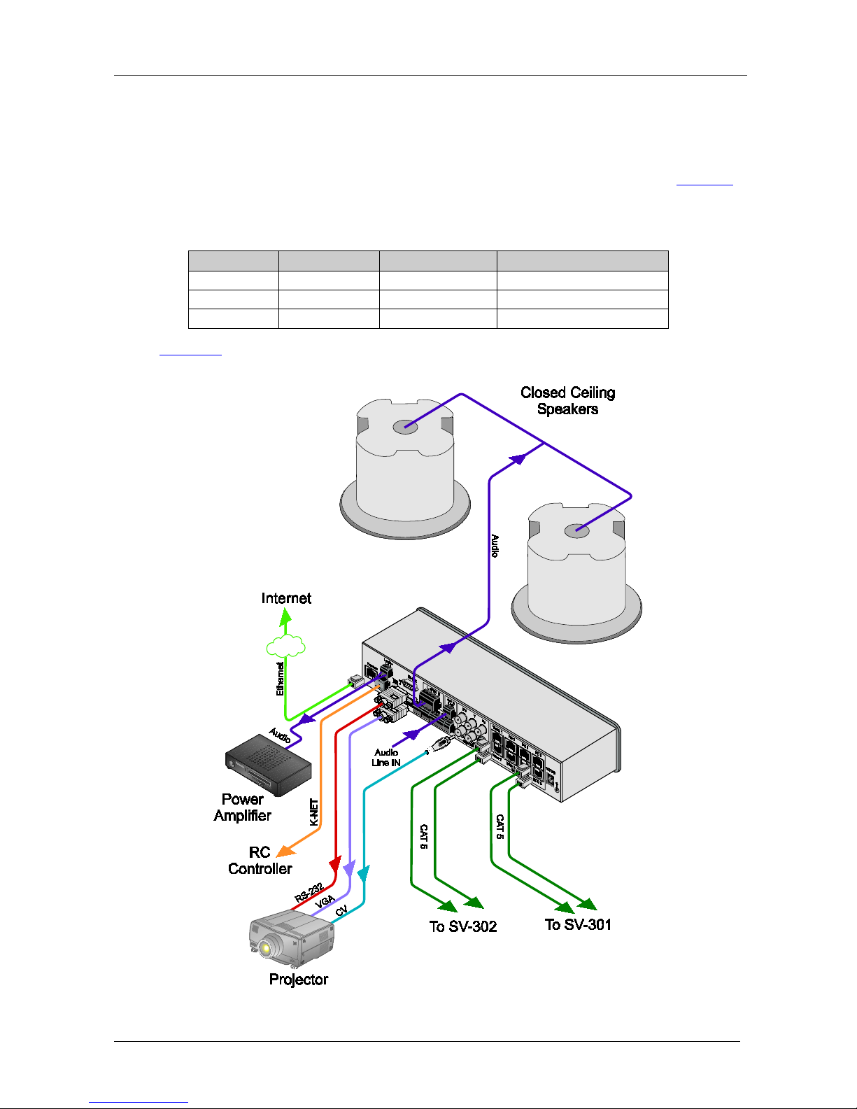
Figure 1 shows an example of how the Closed-back Ceiling speakers can be
installed in a boardroom setup:
Figure 1: Closed-back Ceiling Speakers in a Boardroom Setup
Page 5

Your Closed-back Ceiling Speaker s
3 3
To achieve the best performance:
• Connect only good quality connection cables
1
• Avoid interference from neighboring electrical ap pliances and positio n
your Kramer Closed-back Ceiling speakers a w ay fro m mo ist u r e,
excessive sunlight and dust
, thus avoiding int erference,
deterioration in signal q uality due to poor matching, and elevated noiselevels (often associated with low quality cables)
4 Your Closed-back Ceiling Speakers
Figure 2 and Figure 3 define the SPK-CC678 and the SPK-CCV448 and
SPK-CCV444, respectively.
1 Such as the Kramer BC-2S cable
Page 6

KRAMER: SIMPLE CREATIVE TECHNOLOGY
Your Closed-back Ceiling Speakers
4
Figure 2: SPK-CC678 Closed-back Ceiling Speaker
Figure 3: SPK-CCV448 / SPK-CCV444 Closed-back Ceiling Speaker
Page 7

Your Closed-back Ceiling Speaker s
5 5
Table 2 defines t he Closed-back Ceiling speaker hardware items (per speaker
pair):
Table 2: Closed-back Ceiling Speakers Hardware Items
Description
A pair of
ceiling
speakers
(one shown
1
)
Two grilles
(one shown)
Cutout
template
Table 3 defines the ceiling mountin g k it items:
Table 3: Ceiling Mounting Kit Items
Four
support
ring screws
Two
ceiling
support
rings
(C-ring) –
one shown
Two pairs of
tile rails – one
of a pair
shown
Each Closed-back ceiling speaker is su pport ed by a C-ring and two tile rails2.
When mounting onto the ceiling tiles
3
, use both supports . When mount ing ont o
a sheetrock ceiling, the C-ring alone is used to reinforce th e ceiling material.
Figure 4 shows a schematic diagram of the closed-back ceiling speaker:
1 The quantity applies to all models
2 The tile rails prevent the speakers from falling if the tile itself comes out or falls apart, as their ends catch onto the T-grid
3 Be sure that the tiles can support the spea ker. Smaller sized tiles or fiberglass-type tiles ca nnot support the weight of the
speakers. When this is the case, the speakers will need additional support
Page 8

KRAMER: SIMPLE CREATIVE TECHNOLOGY
Installing the Closed-back Ceiling Speakers
6
Figure 4: Closed-back Ceiling Speaker Schematic Diagram
5 Installing the Closed-back Ceiling Speakers
This section explains ho w to install the closed-back ceiling speakers, that is:
• Choosing the best place to locate your speakers (see section
5.1)
• Cutting the ceiling tile (see section
5.2)
• Mounting the Speakers (see section
5.3)
• Painting the speakers (see section
5.4)
5.1 Choosing the Best Location
Ideally, locate the speakers above the main listening area. Before doing so, be
sure that:
• The desired location is free of obstructions, such as electrical piping, AC
ducts or water lines, and so on
• There i s enough space behind the mounting surface for the speakers
• Rear side of the speaker is not blocked by wall studs or other objects
Page 9

Installing the Closed-back Ceiling Speakers
7 7
5.2 Cutting the Ceiling Tile
To cut the ceiling tile, do the f ollowing:
1. Remove the circle in the supplied template
1
2. Mark the opening in the correct location by tracing the hole in the template.
.
3. Cut out the hole a c c ording to the template or with a circular cutter set to
the appropriate cutout size
2
4. Route the wiring from the amplifier to the speakers’ cutout holes, taking
care not to place them next to electrical wires or at least at a distance of
about two feet from an AC line
.
3
If you are mounting the speakers onto a ceiling tile, remove the ceiling tiles
where you plan to install the s p eakers. Use the template to trace and then
cutout the speake r hole over an empt y box.
.
The closed-back ceiling speakers are supported by the ceiling mounting kit
(two C-rings and two pairs of tile rails
4
). When mounting o nto the ce iling
tiles
5
, use both supports. When mounting onto a sheetrock ceiling, the C-ring
alone is used to reinforce the ceiling material.
1 Keep this template for later use as a mask, as you may want to paint the speakers (see section 5.3)
2 Initially, you can cut a smaller area inside the marked hole just to be sure that the space above the speakers is clear
3 Do not nail or staple the speaker wires
4 The tile rails prevent the speakers from falling if the tile itself comes out or falls apart, as their ends catch onto the T-grid
5 Be sure that the tiles can support the spea ker. Smaller sized tiles or fiberglass-type til es cannot support the weight of the
speakers. When this is the case, the speakers will need additional support
Page 10

KRAMER: SIMPLE CREATIVE TECHNOLOGY
Installing the Closed-back Ceiling Speakers
8
5.3 Mounting the Speakers
To install the closed-back ceiling speakers, do the following:
1. Place the C-ring over the hole c ut in t he ce iling tile (on the “ceiling”
side). Place it around the hole so that the tabs are located in parallel to the
tile edges (see
Figure 5).
T-channel Grid
Support Ring
Screws
Ceiling Tile
Tile Rails
C-ring
Figure 5: Installing the Closed-back Ceiling Speakers
2. Place the tile r a ils on the tile and snap the m into the two tabs on the
C-ring.
Align the r ails so that the e nds extend over the T-channe l gr i d .
3. Insert a screw through each tab on the C-ring to secure the rails.
4. Connect the speaker wires to the appropriate connector terminals
1
and
screw the hold-down screws on the connector until tight
2
Wiring in parallel: connect the wire pair of the subsequent speaker
to PIN 2 and PIN 3. When one input connector is removed,
subsequent speakers will remain connected (see
.
You can connect the speakers in the two following possible layouts:
Figure 4)
Daisy-chaining: connect the wire pair of the subsequent speaker to
PIN 1 a nd PIN 4. W hen one inp ut connector is removed, subsequent
speakers will be disconnected (see
Figure 4)
5. Plug the connector into the socket in the terminal cup of the speaker (see
Figure 6).
6. Run the wires through the wires’ op ening in t he input te rminal cover plug
and then into the terminal block connector of the speaker.
1 PIN 1 and PIN 2 are connected internally and are positive (+). PIN 3 and PIN 4 are connected internally and are negative (-)
2 Use a small screwdriver
Page 11

Installing the Closed-back Ceiling Speakers
9 9
Figure 6: Plugging and Securing t he Ca ble
7. Push the speaker into t he ceiling hole until the front baf fl e rim is leveled
with the ceiling.
8. Tighten the mounting tabs by turning the screw counter clockwise
1
(see
Figure 7).
When tightening the mounting tabs, the tab s automatically t urn outward,
thus clamping the speaker to the wall from its rear side.
Note: Do not over-tighten the screws. It ma y cause damage to both the
speakers and the surface.
Figure 7: Tighten the Mounting Tabs
9. If required, you can further secure the speaker by connecting the speaker
support ring to an independ ent secure anchor point.
10. Adjust each speaker to the appropriate tap setting before insta lling the
grille (see
Figure 8).
1 The first quarter turn, rotates the tab outwards, and the following turns tighten the tabs to the rear side of the ceiling surface
Page 12

KRAMER: SIMPLE CREATIVE TECHNOLOGY
Installing the Closed-back Ceiling Speakers
10
Figure 8: Adjust Tap Selector (for the SPK-CC678)
11. Install the grilles to the speakers:
Push the grille fastener i nto the hole in front of the baffle
Press the grille into place until the front of the grille is flush with the
rim of t h e baffle
Check that the grille is securely seated
1
5.4 Painting the Speaker
You can paint the speakers before or after they are installed.
When painting before installation:
• Clean the rim and grille with mi ner a l sp irits or other light solvent that is
unlikely to d amage the surface
• Spray with color by holding the spray can at an angle of 45°
Note: When spraying the grill e, take care not to clog the holes in the grille
as this will greatly reduce the sound quality of the speakers
When painting after installation:
• Use the circle that you cut out of the template as a paint mask
• After yo u finish pa inting, r emove t he paint mask
1 To remove the grille, insert two bent paper clips into the holes in the grille and carefully pull it down. Repeat this around the
perimeter of the grille until it is completely removed
Page 13

Technical S pecifications
11 11
6 Technical Specifications
Table 4 and Table 5 include the technical specifications
1
Table 4: Technical Specifications of the SPK-CC678
of the closed-back
ceiling speakers:
DESCRIPTION: 2-way co-axial speaker
HIGH FREQU ENCY DRI VER : 1” MYLAR dome tweeter
LOW FREQUENCY DRIVER: 6.5” Polypropylen e cone with rubb er edge
woofer
IMPEDANCE: 8Ω
CROSSOVER FREQUENCY: 8kHz
SENSITIVITY: 87dB
FREQUENCY RESPONSE: 55Hz to 20KHz
POWER RATING: 30W nominal, 60W Max.
RECOMM END ED AMPL IF IER POWER: 30W
WEIGHT PER SINGLE SPEAKER: 2.85kg (6.28lbs) approx.
SHIPPING WEIGHT (FOR PAIR): 8kg (17.64lbs) approx.
DIMENSIONS (OD): 25.2cm (9.92")
CUT OUT SIZE (MOUNT DIMENSION): 22.3cm (8.78")
MOUNT DEPTH: 19.5cm (7.68”)
ACCESSORIES: Ceiling mounting kit
Table 5: Technical Specifications of the SPK-CCV448 and the SPK-CCV444
SPK-CCV444 SPK-CC448
DESCRIPTION: 2-way co-axial speaker
HIGH FREQU ENCY DRI VER : 1” MYLAR tweeter
LOW FREQUENCY DRIVER: 4” Polypropylene cone with rub ber edge woofer
IMPEDANCE: 4Ω 8Ω
CROSSOVER FREQUENCY: 10kHz 10kHz
SENSITIVITY: 85 dB 85dB
FREQUENCY RESPONSE: 85-20KHz 95-20KHz
POWER RATING: 20W nominal, 40W
Max.
20W nominal, 40W
Max.
RECOMM END ED AMPL IF IER POWER: 20W 20W
WEIGHT PER SINGLE SPEAKER: 2.2kg (4.85lbs) approx.
SHIPPING WEIGHT (FOR PAIR): 6kg (13.23lbs) a pprox .
DIMENSIONS (OD): 25.2cm (9.92")
CUT OUT SIZE (MOUNT DIMENSION): 22.3cm (8.78")
MOUNT DEPTH: 10.8cm (4.25”)
ACCESSORIES: Cei ling mount ing kit
1 Specifications are subject to change without notice
Page 14

KRAMER: SIMPLE CREATIVE TECHNOLOGY
12
LIMITE D WARRAN TY
WHO IS PROTECTED?
WHA T IS COVERED AND WHA T I S NOT COVERED
WHAT WE WILL PAY FOR AND WHAT WE WILL NOT PAY FOR
HOW YOU CAN GET WARRANTY SERVICE
LIMITA TION OF IMPLIED W ARRANTIES
EXCLUSION OF DAMAGES
CAUTION!
Kramer Electronics (hereafter ) warrants this product free from defects in material and wor kma nship unde r the
following terms.
Kramer
HOW LONG IS THE W ARRANTY
Labor and parts are warranted for one year from the date of the first customer purchase.
Only the first purchase customer may enforce this warranty.
W e will p ay labor and ma teria l expen ses for cover ed item s. W e wi ll not pa y for th e fol lowing:
The li abil ity of Krame r for any e ffe ct ive pr oduc ts is l imi ted t o the repair or re pla ceme nt of the pro duc t at ou r op tion. Kram er sha ll
not be liabl e for:
This wa rran ty give s you spec ific l egal rights , and yo u may al so have other r ights, w hich va ry fr om place to place.
All produ cts ret urned t o Krame r for service must hav e pri or approv al. This ma y be obt ained f rom you r deal er.
This e quipm ent has b een tes ted to determi ne co mpliance with t he requ ireme nts of:
EN-50 081: "Ele ctrom agnetic c ompat ibili ty (EMC );
generic emission standard.
Resi denti al, co mmercia l and l ight ind ustry "
EN-50 082: "Ele ctrom agnetic c ompat ibili ty (EMC ) gener ic immu nity st andar d.
Part 1 : Reside ntia l, comm ercial and lig ht indus try e nviro nment".
CFR-47: FCC* Rules and Regulations:
Part 15 : “Ra d io f r equency devices
Subpart B Unintentional radiators”
Except as below, this warranty covers all defects in material or workmanship in this product. The following are not covered
by the warranty:
1. Any product which is not distributed by Kramer, or which is not purchased from an authorized Kramer dealer. If you are
uncertain as to whether a dealer is authorized, please contact Kramer at one of the agents listed in the Web site
www.kramerelectronics.com.
2. Any product, on which the serial number has been defaced, modified or removed, or on which the WARRANTY VOID
TAMPER E D sti c ke r ha s be e n to r n,
3. Damage, deteri oratio n or ma lfuncti on resu lting from:
i) Accident, misuse, abuse, neglect, fire, water, l ightn ing or oth er ac ts of nat ure
ii) Produc t modi ficati on, or fa ilur e to foll ow instr ucti ons sup plied w ith the produ ct
iii) Rep air o r attemp ted re pair by a nyone not auth oriz ed by Kra mer
iv) Any ship ment o f the pr oduct ( claim s must b e presen ted to the carr ier)
v) Remova l or i nstalla tion of the pro duct
vi) Any other cause, which does not relate to a product defect
vii)Cartons, e quipm ent encl osure s, cabl es or accesso ries use d in c onjunc tion wi th the p roduct
1. Rem oval or insta llatio ns char ges.
2. Costs of initial technical adjustments (set-up), including adjustment of user controls or programming. These costs are the
respon sibi lity of the Kra mer deal er fr om whom t he produ ct wa s purcha sed.
3. Shipp ing char ges .
1. To obtain service on you product, you must take or ship it prepaid to any authorized Kramer service center.
2. Whenever warranty service is required, the original dated invoice (or a copy) must be presented as proof of warranty
coverage, and should be included in any shipment of the product. Please also include in any mailing a contact name,
company, address, and a description of the problem(s).
3. For the name of the nearest Kramer authorized service center, consult your authorized dealer.
All implied warranties, including warranties of merchantability and fitness for a particular purpose, are limited in duration to
the length of this warranty.
1. Damag e to other prop erty cau sed by def ects in this product , damage s based upon inc onven ience , loss of use of the produ ct, los s
of time, commercial lo ss; o r:
2. Any ot her dam ages , w het her i nci den tal, conse que nti al o r o the rwise . S ome c oun tri es ma y n ot a llow lim ita tion s on ho w lon g a n
implied warranty lasts and/or do not allow the exclusion or limitation of incidental or consequential damages, so the above
limit ation s and exc lusio ns may no t apply to yo u.
Servicing the machines can only be done by an authorized Kramer technician. Any user who makes changes or
modifications to the unit without the expressed approval of the manufacturer will v oid user authority to operate the
equipment.
Use th e suppl ied DC p ower sup ply t o feed p ower to t he mach ine.
Please use recommended interconnection cables to connect the machine to other components.
IF reattached, removed or otherwise interfered with.
* FCC and CE app roved usi ng STP cable ( for twi sted pa ir produ cts)
NOTE:
Part 1 :
Page 15

Kramer Electronics, Ltd.
Web site: www.kramerelectronics.com
E-mail: info@kramerel. com
P/N: 2900-000692 REV 1
For the latest information on our products and a list of Kramer
distributors, visit our Web site: www.kramerelectronics.com,
where updates to this user manual may be found.
We welcome your questions, commen ts and feedba ck .
 Loading...