

Page 1

Kramer Electronics, Ltd.
USER MANUAL
Model:
SP-11HD
HD-SDI Processor
Page 2

Contents
i
Contents
1 Introduction 1
2 Getting Started 1
2.1 Quick Start 2
3 Overview 3
4 Your SP-11HD HD-SD I Processor 4
5 Installing the SP-11HD HD-SDI Pro ces sor in a Rack 8
6 Connecting the SP-11HD HD-SDI Pro cessor 9
6.1 Connecting the RS-232 Port 10
6.2 Setting the DIP-Switches 11
7 Operating the SP-11HD HD-SDI Processor 12
7.1 Storing/Recalling Setups 13
7.2 Locking the Front Panel 14
7.3 Black Screen/Blue Screen Selection 14
8 Technical Specifications 15
9 Communication Protocol 16
Figures
Figure 1: SP-11HD HD-SDI Processor Funct i ons 5
Figure 2: Connecting the SP-11HD HD-SDI Processor 10
Figure 3: Connecting a PC Without Using a Null-Modem Adapter 11
Tables
Table 1: SP-11HD HD-SDI Processor Functi ons 6
Table 2: DIP-Switch Settings 11
Table 3: Test Signals 11
Table 4: Technical Specifications of the SP-11HD HD-SDI Processor 15
Table 5: Structure of the Protocol 16
Table 6: Instruction Set 17
Page 3

Introduction
1
1 Introduction
Welcome to Kramer Electronics! Since 1981, Kramer Electronics has been
providing a world of unique, creative, and affordable solutions to the vast
range of problems that confront the video, audio, presentation, and
broadcasting professional on a daily basis. In recent years, we have
redesigned and upgraded most of our line, ma king the best even b etter! Our
1,000-plus different models now appear in 11 groups
1
Thank yo u for purchasing the Kra mer SP-11HD HD-SDI Processor, which
is ideal for:
that are clearly
defined by function.
• Video broadcasting and editing studios
• All postproduction uses
• Presentation applications for multi-standard / multi-format sources use
Each package includes the following items:
• The SP-11HD HD-SDI Processor
• Power cord
2
• This user manual
3
2 Getting Started
We recommend that you:
• Unpack t he equip ment carefully and s ave the original box and
packaging materials for possible future shipment
• Review the contents of this user manual
• Use Kramer high-performance high-resolution cables
4
1 GROUP 1: Distribution Amplifiers; GROUP 2: Switchers and Matrix Switchers; GROUP 3: Control Systems;
GROUP 4: Format/Standards Converters; GROUP 5: Range Extenders and Repeaters; GR OUP 6: Specialty AV Products;
GROUP 7: Scan Converters and Scalers; GROUP 8: Cables and Connectors; GROUP 9: Room Connectivity;
GROUP 10: Accessories and Rack Adapters; GROUP 11: Sierra Products
2 We recommend that you use only the power cord supplied with this device
3 Download up-to-date Kramer user manuals from our Web site at
http://www.kramerelectronics.com
4 The complete list of Kramer cables is on our Web site at
http://www.kramerelectronics.com
Page 4
KRAMER: SIMPLE CREATIVE TECHNOLOGY
Getting Started
2
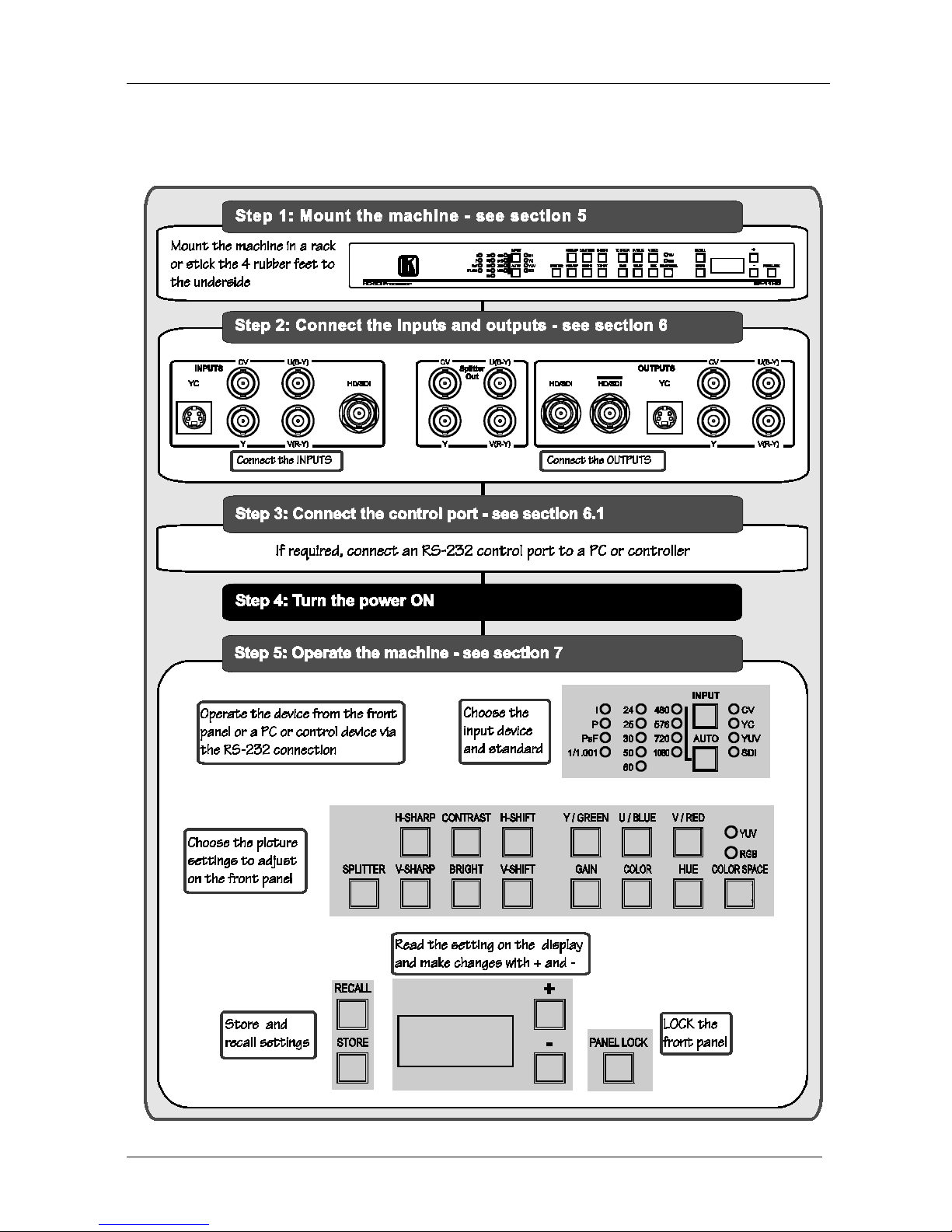
2.1 Quick Start
This quic k start chart summarizes the basic setup and operation steps.
Page 5

Overview
3
3 Overview
The Kramer SP-11HD is a multi-standard/multi-format, broadcast-quality
video processor and ProcAmp. It is a universal single-box solution for all
your video processing requir ements.
The SP-11HD HD-SDI Processor features the following:
• Inputs: composite video, s-Video, component video (YUV), SD/HD-SDI
• Outputs
1
• Input Video Standards: composite PAL-B, PAL-M, PAL-N,
NTSC-3.58, NTSC -4.43, SECAM; component (with auto
identification) 480i/60, 480p/60, 576i/50, 576p/50, 720p/ 50, 720p/60,
1080p/24, 1080p/2 5, 1080 p/ 30, 1080i/25, 1080i/30, 1080i/50,
1080i/60, 1080psf/24, 1080psf/25, 1080psf/30
: composite video, s-Video, component video (YUV),
SD/HD-SDI (2 outputs), “Before/after” split-screen
• ProcAmp Functions: video gain, brightness, contrast, color, hue,
and sharp ness (independent H and V ). A full r ange of co lor control
features in both YUV and RGB color space
• 5-line super-adaptive 2D comb filter for CVBS decoding
• Individual H and V chroma-luma delay
In addition, the SP-11HD Digital Video Processor includes:
• 16 non-volatile memory setups available for saving the settings
• Power-down save
• A screen splitter that provides simultaneous "before and after"
image comparison on one monitor
• Full 10-bit digital processing throughout, for the highest possible
video quality
Control the SP-11HD:
• Using the front pa nel buttons and the 7-segment display
• Remotely, by RS-232 serial commands transmitted by a touch
screen system, PC, or other serial controller
1 All output formats are always available except where a format does not support the resolution in use. For example,
composite video and s-Video outputs are not available when an HD input (e.g. 1080p) is used
Page 6

KRAMER: SIMPLE CREATIVE TECHNOLOGY
Your SP-11HD HD-SDI Processor
4
To achieve the best performance:
• Use only good quality connection cables
1
• Avoid interference from neighboring electrical appliances that
may adversely influence signal quality and position your Kramer
SP-11HD away from moisture, excessive sunlight and dust
to avoid interference,
deterioration in signal q ualit y due to poor matching, and elevated
noise levels (often associa te d with low quality cables).
4 Your SP-11HD HD-SDI Processor
Figure 1 and Table 1 define the unit.
1 Available from Kramer Electronics on our Web site at http://www.kramerelectronics.com
Page 7
Your SP-11HD HD-SDI Processor
5
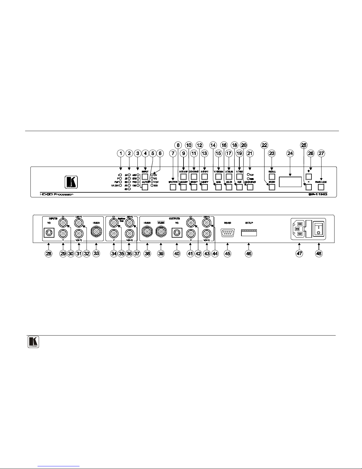
Figure 1: SP-11HD HD-SDI Processor Functions
Page 8

KRAMER: SIMPLE CREATIVE TECHNOLOGY
Your SP-11HD HD-SDI Processor
6
Table 1: SP-11HD HD-SDI Processor Functions
#
Feature
Function
1 Scanning Format LEDs i = interlaced
p = progressive
PsF = progressive segmented frame
1/1.001 l ights in HDTV mode on ly if the frame ra te is 2 3.9 8, 29. 97
or 59.94 (instead of 24, 30 or 60 respectively)
2 Field/Frame Rate LEDs Corresponds to 24, 25, 30, 50 and 60 fields/s (interlaced) or
frames/s (progressive and Psf).
3 Active Lines Per Frame LEDs Corresponds to 48 0, 576 , 7 20 and 1080 lines per frame
4 INPUT Selector Button Press to select t he source , illumin at ing th e appr opr iate LED
5 AUTO Button Toggles between a uto mat ical ly re cogn izing th e inpu t st andar d
(lighting the appropr iate LEDs) and the manua l selection mode.
The cycle sequence: AUTO, 480 i/60, 480p /60 , 576i /50 , 576p /50,
720p/50, 720p/59.94 , 720p/60, 1080 i/25, 10 80 i/50, 1080 i/59.94,
1080i/25, 1080i/29.97, 1080i /30 , 1080p /23 .98 , 1080p /24 ,
1080p/60, 1080p/ 29.97, 108 0p/ 30, 108 0psf/ 23. 98, 1080ps f/2 4,
1080psf/25, 10 80psf/ 29. 97 a nd 1080p sf /30 .
Note: Standards 1080psf/25, 1080p sf/29 .97 and 1080psf /30 in
AUTO mode are identified as 1080i/50, 1080 i /59 .94, 10 80i /25,
respectively. If the input sour ce is CVBS or Y/C, the cycling
sequence is redu ced to t hree modes: AUTO, 480 i/6 0 and
576i/50.
6 INPUT LEDs Cycles through the video sou rces: CV, YC, YUV and SDI
7 SPLITTER Button Press the SPLITTER button and adjust the position of the
boundary between the edited image an d the or ig inal image in a
split screen using the + and - buttons
8 V-SHARP Button Press the V-SHARP button a nd adj us t the ver t ical sha rpne ss
using the + and – buttons
9 H-SHARP Button Press the H-SHARP button and adjust the horizontal sharpness
using the + and – buttons
10 BRIGHT Button Press the BRIGHT button and adjus t the brig htnes s u sing the +
and – buttons
11 CONTRAST Button Press the CONTR AST bu tton a nd adj ust u sing the + and –
buttons
12 V-SHIFT Button Press the V-SHIFT button and adjust V-Chroma-Luma delay
using the + and – buttons
13 H-SHIFT Button Press the H-SHIFT button and adjust the H-Chroma-Luma delay
using the + and – buttons
14 GAIN Button Press the VIDEO GAIN button and adjust the using the + and –
buttons
15 Y/GREEN Button Press the Y1/GREEN
2
16
button and adjus t u sing t he + and –
buttons, when COLOR SPACE button is activ ated
COLOR Button Press the COLOR
3
17
button and adjus t using the + and – buttons
U/BLUE Button Press the U1/BLUE2 button and ad just us ing t he + and – buttons,
when COLOR SPACE button is activated
18 HUE Button Press the HUE button and adjust using the + and – buttons. This
function is availab le for a ll i nput a nd o utp ut for mats and stand ards
1 For YUV
2 For RGB
3 Pressing the + button enhances dull colors. Pressing the – button reduces distortion (snow)
Page 9

Your SP-11HD HD-SDI Processor
7
7
#
Feature
Function
19 V/RED Button Press the V1/RED
2
20
button and adjust us ing the + and – buttons,
when COLOR SPACE button is activated
COLOR SPACE Butto n Press to select the color space of color control; if the COLOR
SPACE button does n’t illuminate, color control is disabled in any
color space
21 YUV/RGB LEDs Cycle between di ff erent co lor space s of co lor c ontr ol: YUV and
RGB. The corresponding LED lig hts
22 STORE Button Stores the current setup in the non-volatile memory
3
23 RECALL Button Recalls a setup fro m the non-volatile memory3
24 7-segment Display Displays data w hen us ing a front pan el button
25 - Button Press to decrease the level
26 + Button Press to increase the level
27 PANEL LOCK Button Disengages/engages the front pan el bu ttons ( press and hold
down for 2 seconds to toggle)
28
INPUTS
Y/C 4-pin Conn ector Connects to the s-Vide o source
29 Y B NC Connec tor Connects to the Y component of the YUV source
30 CV BNC Connector Connects to the composite video source
31 V(R-Y) BNC Connector Connects to the V component of the Y UV sour ce
32 U(B-Y) BNC Con nector Connects to the U c o mponent of the YUV source
33 HD-S DI BNC Conne ctor Connects to the HD-SDI sou rce
34
OUTPUTS
SPLITTER Y BNC Connector Connects to the split image Y co mponent o f the YUV acceptor
35 SPLITTER CV BNC Connector Conne cts to the split image CV acceptor
36 SPLITTER V BNC Connector Connects to the split image V component of the Y UV acceptor
37 SPLITTER U BNC Connector Connects to the split image U component o f the YUV acceptor
38 HD/SDI BNC Connector Connects to the serial dig ital video a cceptor 1
39 HD/SDI BNC Connector Connects to the serial digital video a cceptor 2
40 YC 4-pin Connector Connects to the s-Video (Y/C) a cceptor
41 Y B NC Connec tor Connects to the Y input of the YUV acceptor
42 CV BNC Connector Connects to the composite video acceptor
43 U(B-Y) BNC Connector Connects to the U input of the YUV acceptor
44 V(R-Y) BNC Connec tor Connects to the V input of the YUV acceptor
45 RS-232 Port Connects to the PC or the re mote controller
46 SETUP DIP-switches Use to conf igu re and test the un it (see section 6.2)
47 Power Connector with Fuse AC connector en abli ng pow er supp ly t o the un it
48 Power Switch Illu minated swi tch for tur ning the un it ON or OFF
1 For YUV
2 For RGB
3 See section
7.1
Page 10

KRAMER: SIMPLE CREATIVE TECHNOLOGY
Installing the SP-11HD HD-SDI Processor in a Rack
8
5 Installing the SP-11HD HD-SDI Processor in a Rack
This section describes how to install the SP-11HD in a rack.
Before Installing in a rack
How to Rack Mount
Before installing in a rack, be sure that the environment is
within the recommended range:
To rack-mount a machine:
1. Attach both ear brackets to the
machine. To do so, remove the
screws from each side of the
machine (3 on each side), and
replace those screws through the
ear brackets.
2. Place the ears of the machine
against the rack rails, and insert the
proper screws (not provided)
through each of the four holes in the
rack ears.
Note that:
• In some models, the front panel
may feature built-in rack ears
• Detachable rack ears can be
removed for desktop use
• Always mount the machine in the
rack before you attach any cables
or connect the machine to the
power
• If you are using a Kramer rack
adapter kit (for a machine that is not
19"), see the Rack Adapters user
manual for installation instructions
(you can download it at:
http://www.kramerelectronics.com)
Operating temperature range
+5° to +45° C (41° to 113° F)
Operating humidity range 10 to 90% RHL, non-condensing
Storage temperature range
-20° to +70° C (-4° to 158° F)
Storage humidity range 5 to 95% RHL, non-condensing
!
CAUTION!!
When installing on a 19" rack, avoid hazards by taking
care that:
1. It is located within the recommended environmental
conditions, as the op era ti ng ambi ent t e m pera tur e of a
closed or multi unit rack assembly may exceed the
room ambient temperature.
2. Once rack mounted, enough air will still flow around
the machine.
3. The machine is placed straight in the correct
horizontal positi on.
4. You do not overload the circuit(s). When connecting
the machine to the supply circuit, overloading the
circuits might have a detrimental effect on overcurrent
protection and supply wiring. Refer to t he app ro priate
nameplate ratings for information. For example, for
fuse replacemen t, s ee the value printed on the
product label.
5. The machine is earthed (grounded) in a reliable way
and is connected onl y to an ele ctric ity socket with
grounding. Pay particular attention to situations where
electricity is supplied indirectly (when the power cord
is not plugged directly into the socket in the wall), for
example, when using an extension cable or a power
strip, and that you use only the power cord that is
supplied with the machine.
Page 11

Connecting the SP-11HD HD-SDI Processor
9
9
6 Connecting the SP-11HD HD-SDI Processor
You can use your SP-11HD to convert1 composite video, s-Video,
component video (YUV), or SDI signals to composite video (PAL or
NTSC), s-Video, component video (YUV) and
2
Figure 2
SDI, as well as to a
“Before/after” split-screen, as the example illustrates in .
To connect
3
the SP-11HD Digital Video Processor, do the following
4
1. Connect the following sources to the SP-11HD:
:
• The composite video source (for example, a DVD player) to
the CV INPUT BNC connector
• The s-Video source (for example, an S-VHS player) to the
Y/C INPUT 4-pin connector
• The SDI source (for example, a digital video player) to the
SDI INPUT BNC connector
2. Connect the component video INPUTS BNC connectors, Y, B-Y, and
R-Y to YUV video source.
3. Connect the following acceptors to the SP-11HD:
• The SPLITTER OUT PUT BNC connector to the split image
acceptor (for example, a display)
• The Y/C OUTPUT 4-pin connector to an s-Video acceptor
(for example, a display)
• The CV OUTPUT BNC connector to a composite video
acceptor (for example, a display)
• The BNC OUTPUTS connectors: Y, B-Y and R-Y to a video
acceptor (for example, a plasma display)
• The two SDI OUTPUTS BNC connectors to two serial digital
video acceptors (for example, two monitors: SDI 1 and SDI 2)
4. Connect a PC or other controller, if required (see section
6.1).
5. Set the DIP-switch es (s ee s ecti on
6.2).
6. Connect the AC power cord.
1 The SP-11HD does not perform standard conversion or scaling. The output resolution is always identical to the input
resolution
2 All output formats are always available when the format is valid for the input resolution being used
3 When only one output is required, connect that output of the SP-11HD, and leave the other outputs unconnected
4 Switch OFF the power on each de vice before connectin g it to your SP-11HD. After connecting your SP-11HD, switch on
its power and then switch on the power on each device
Page 12

KRAMER: SIMPLE CREATIVE TECHNOLOGY
Connecting the SP-11HD HD-SDI Processor
10
Figure 2: Connecting the SP-11HD HD-SDI Proces sor
6.1 Connectin g th e RS-232 Port
To connect a PC
1
• Connect the RS-232 9-pin D-sub rear p anel port on the Master
SP-11HD unit to the null-modem adapter and connect the nullmodem adapter with a straight cable to the RS-232 9-pin D-sub
port on your PC
to the SP-11HD unit, using the null-modem adapter
provided with the machine (recommended):
To connect a PC to the SP-11HD unit, without using a null-modem adapter:
• Connect the RS-232 9-pin D-sub port on your PC to the RS-232
9-pin D-sub rear panel port on the Master SP-11HD unit, using a
cable illustrated in
Figure 3 :
1 Or some other RS-232 remote control system
Page 13

Connecting the SP-11HD HD-SDI Processor
11
11
Figure 3: Connecting a PC Without Using a Null-Modem Adapter
6.2 Setting the DIP-Switches
Configur e the SP-11HD unit by setti ng the 8 DIP-switches, as defined in
Table 2 and Table 3:
Table 2: DIP-Switch Settings
DIP-Switch
Set as follows:
1 PEDESTAL ON for pedestal o f outpu t signa l (7.5 I R E off set se lect io n for
NTSC); OFF for n o p edes tal
2 Input sync bi-level or tri-level
(HDTV)
Active only in HDTV mode: ON for bi-level input sync, OFF for
tri-level.
3 Output sync bi-leve l or tri-level
(HDTV)
Active only in HDTV mode: ON for bi-level output sync, OFF for
tri-level.
4 TEST - 4 These three switch es define test si gnals (see Tab le 3 )
5 TEST - 5
6 TEST - 6
7 AGC ON to enable Auto Gain Control ; OFF to disable
8 ADDR Defines address of machine: OFF – 0x18; ON – 0x19
Table 3: Test Si gnals
#
TEST-4
TEST-5
TEST-6
Test Signal
1 OFF OFF OFF Normal operating mode, no test active
2 ON OFF OFF RAMP 100%
3 OFF ON OFF Y-SWEEP (5.8MHz – SD TV, 11.6MHz – EDTV, 30MHz – HDTV )
4 OFF OFF ON COLOR BARS 100%
5 ON ON OFF SPLIT BARS 100%
6 OFF ON ON PULSE 2T and BAR
7 ON OFF ON C-SWEEP (1.5MHz – SDTV, 3MHz – EDTV, 15MHz – HDTV )
8 ON ON ON GRID
Page 14

KRAMER: SIMPLE CREATIVE TECHNOLOGY
Operating the SP -11 HD HD-SDI Processor
12
7 Operating the SP-11HD HD-SDI Processor
Operate your SP-11HD via:
• The front panel but t ons
• RS-232 serial commands transmitted by a touch scre en system,
PC, or other serial co ntroller
To operate the SP-11HD using the front panel buttons, do the following:
1. Turn on the power and press the INPUT button to select the source to
convert: CV, YC, YUV or SDI.
The appropriate INPUT LED lights (indicating selection of that source).
2. Press the AUTO button to select input standard that cycles as follows:
AUTO, 480i/60, 480p/60, 576i/50, 576p/50, 720p/50, 720p/59.94, 720p/60,
1080i/50, 1080i/59.94, 1080i/60, 1080p/23.98, 1080p/24, 1080p/25,
1080p/29.97, 1080p/30, 1080psf/23.98, 1080psf/24, 1080psf/25,
1080psf/29.97 and 1080psf/30.
With a CVBS or Y/C input source, the cy clin g se quen ce i s redu ced to th ree
modes: AUTO, 480i/60 and 576i/50. The appropriate 1/1.001 LED, one
SCANNIN G FORM AT LED, one FIELD/FRAM E RAT E L ED and one
ACTIVE LINES PER FRAME LED lights. If the AUTO button does not
illuminate, it means a forced input standard. Otherwise, the AUTO button
illuminates, lighting LEDs to indicate the detected input standard.
3. Adjust the color, brightness, contrast, hue, sharpness
1
, H-shift, V-shift
2
• Press the appropriate button
,
and/or video gain of the picture, as follows:
3
• Press the + button or - button once to gradually increase or
decrease the current level by one unit (the 7-segment display
shows the new level)
To increase or decrease the current level rapidly, press and
hold the + button or - button, continuously
The butt on illuminates and blinks a nd the 7-segment display
shows the current level (in dig its) . “0” c orresponds to normal
level (“NORM”)
4
1 Using the V-SHARP and H-SHARP buttons
To end the rapid adjustment, release the + button or – button
2 Using the V-SHIFT and H-SHIFT buttons
3 See the relevant items defined in
Table 1
4 The 7-segment display starts to quickly scan the range. When it stops running, it has reached the maximum or minimum,
respectively
Page 15

Operating the SP -11 HD HD-SDI Processor
13
13
• To set “NORM” of the current level rapidly, press and hold
down the + button and – butto n t ogether , continuously, the
7-segment display shows “0”
• To undo the adjustment, press the appropriate button one
more time. The appropriate button no longer blinks
• To save result of adjustment, press the STORE button twice
• To store result of a djustment in other setup #, press the
STORE button once and then select a setup # between 1 and
16 by pressing the + and – button. Then press STORE button
one more t ime
• If the result o f the adjustment equals “NORM”, then the
appropriate button no longer illuminates, otherwise this
button continues to illu minate in main mode
7.1 Storing /Recalling Setups
You can store and recall up to 16 setups (or adjustments) in non-volatile
memory, using the STORE and RECALL buttons together with the + and –
buttons.
To store
1
• Press the STORE button and then select a setup # between 1 and
16 by pressing the + and – buttons (the current s ettings are saved
to that setup #)
a setup, do the following:
• Then pr ess STORE button one more time
To recall a setup, do the following:
• Press the R ECALL button and then select the appropriate # (that
corresponds to the setup #) by pressing the + and – buttons (the
selected setup is recalled)
• Then press RECALL button one more time
1 Storing a new setup over a previous setup # replaces the previous setup #
Page 16

KRAMER: SIMPLE CREATIVE TECHNOLOGY
Operating the SP -11 HD HD-SDI Processor
14
7.2 Locking the Front Panel
To prevent changing the settings accidentally or tampering with the front
panel, lock your SP-11HD. Unlocking releases the protection mechanism.
To lock t he SP-11HD:
• Press the PANEL LOCK button continuously until it illuminates
freezing the front panel controls. Pressing a button has no effect
1
To unlock the SP-11HD:
.
• Press the PANEL LOCK button continuously u ntil the front pa nel
controls unlock and the PAN E L LOCK button no longer illuminates
7.3 Black Screen/Blue Screen Selection
To toggle between black screen and blue screen modes in the absence of a
video signal, do the following:
• Turn the power off
• Press and hold down the U/BLUE button
• Turn on the power while pres sing the U/ BLUE but ton
1 Nevertheless, even though the front panel is locked you can still operate your PC control software
Page 17

Technical Specifications
15
15
8 Technical Specifications
The SP-11HD technical specifications are shown in Table 4:
Table 4: Technical Specifications
1
INPUTS:
of the SP-11HD HD-SDI Processor
1 composite video: 1Vpp/75Ω on a BNC connec tor ;
1 Y/C: 1Vpp/75Ω (Y), 0.3Vpp/75Ω (C) on a 4-pin connector;
1 component: Y/R-Y/B-Y (1Vpp/0.7Vpp/0.7Vpp)/75Ω on BNC connectors;
1 SDI: SMPTE-259M, SMPTE-292M, SMPTE-344M, ITU-R BT.601 on a BNC
connector
OUTPUTS:
1 composite video: 1Vpp/75Ω on a BNC con nector ;
1 Y/C: 1Vpp/75Ω (Y), 0.3Vpp/75Ω (C) on a 4-pin connector;
1 component: Y/R-Y/B-Y (1 Vpp/0 .7 Vpp/0. 7Vpp) /75 Ω on BNC connectors;
2 SDI: SMPTE-259M, SMPTE-292M, SMPTE-344M, ITU-R BT.601 on BNC
connectors
BANDWIDTH: 0.5dB to 5MHz (SDTV), to 10M Hz ( EDT V), to 30M Hz (HD TV), fu l ly loaded
S/N RATIO: 60dB
CONTROLS: Front-panel and RS-232: contr ast, br ightness, vi deo gain, color, hue, H/V
sharpness, H/ V chroma-luma shift; R-Y, B-Y level; screen splitter (process to
bypass); panel lock
INPUT VIDEO
STANDARDS:
CVBS (SDTV): PAL-B/D/G/H/I/M/N, NTSC-3.58/4.43, SECAM;
EDTV: 480p/60, 576 p/50;
HDTV: 720p/50, 720p/59 .94, 7 20p/ 60, 1080 i/50, 1080i/59.94, 1080i/60,
1080p/23.98, 108 0p/ 24, 108 0p/ 25, 108 0p/29.97 , 1 080p /30 , 1080p sf /23.98 ,
1080psf/24, 10 80psf/ 25, 108 0psf/ 29.9 7 and 10 80p sf/ 30
OUTPUT VIDEO
STANDARDS:
Same as input standard w ith these ex ception s: for a C VBS input signa l, the
output standard can be only PAL-B or NTSC-3.5 8 depending on input frame
rate; for EDT V or HDTV input signals, the CVBS output s ignal is n ot avai lable
DIGITAL RESOLUTION: 10 bits
LUMA NON-LINEARITY: 1%
CHROMA / LUM A DE LAY: <15ns
POWER SOURCE: Universal, 100-240V AC, 50/60Hz, 22VA max.
DIMENSIONS: 19” x 7” x 1U W, D, H, rack mountable
WEIGHT: 2.6kg (5.7lbs) approx.
ACCESSORIES: Power cord, null-modem adapter
1 Specifications are subject to change without notice
Page 18

KRAMER: SIMPLE CREATIVE TECHNOLOGY
Communic a t ion Pr ot ocol
16
9 Communication Protocol
RS-232 communication between the SP-11HD and the PC is performed
using this protocol (VER 0.1). The protocol
1
The controller and the machine should be connected via a null-modem
connection, that is, if usi ng a 9-pin D-sub port, connect pin 5 of the PC to
pin 5 of the machine, cross pins 2 and 3, that is, connect pin 2 of the PC to
pin 3 of the machine, and connect pin 3 of the PC to pin 2 of the machine.
On the PC s ide, short pins 4 and 6, and short pins 1, 7 and 8.
uses four bytes of information,
and trans mission settings are 9600 baud, no parity, 8 data bits and 1 stop bit.
Table 5: Struct ur e of t he Protocol
MSB
LSB
INSTRUCTION
0 TO PC I5 I4 I3 I2 I1 I0
7 6 5 4 3 2 1 0
Byte 1
DATA
1 D6 D5 D4 D3 D2 D1 D0
7 6 5 4 3 2 1 0
Byte 2
EXTENDED DATA
1 E6 E5 E4 E3 E2 E1 E0
7 6 5 4 3 2 1 0
Byte 3
MSBs
ADDR
1 E7 D7 1 1 0 0 0
7 6 5 4 3 2 1 0
Byte 4
Note that the MSBs of the DATA (D7) and the EXTENDED DATA (E7) are in the fourth byte.
Terminology:
TO PC is the “DESTINATION BIT”
I4..I0 is the “INSTRUCTION”
D7..D0 is the “DATA”
E7..E0 is the “EXTENDED DATA”
The destination bit, TO PC, is 0 when sending from the PC to the machine, or 1 when sending from the machine
to the PC.
1 This protocol co mplements Kramer’s “Protocol 2000” (Kra mer’s switcher protocol), that is, the two protocols can co-exist
without disturbing one another (according to Protocol 2000’s definitions, the SP-11HD would be machine number 24).
Page 19

Communic a t ion Pr ot ocol
17
17
Table 6: Instr uc t io n Set
#
INSTRUCTION
I5
I4
I3
I2
I1
I0
0 Reset 0 0 0 0 0 0
16 Error 0 1 0 0 0 0
32 Read front-panel switch data 1 0 0 0 0 0
33 Write front-panel switch data 1 0 0 0 0 1
34 Recall 1 0 0 0 1 0
35 Store 1 0 0 0 1 1
61 Identify machine 1 1 1 1 0 1
DESCRIPTION OF INSTRUCTIONS
Inst
No
Instruction n am e Data
Number
Data Name Extended Notes
0
RESET 0 Initialize machine 0 When the machine is initialized, it sends the
RESET code (DATA = 0). If the machine receives
this code, it resets to its “power-up” state.
1 Configure the
machine to its
factory default
state
0 When the machine receives this code, all
programmable parameters are reset to their factorydefault values.
16
ERROR If the machine receives an invalid instruction, it
replies by sending this error code.
32
READ FRONT
PANEL SWITCH
DATA (send)
Front panel
switch number*
0
READ FRONT
PANEL SWITCH
DATA (reply)
Front panel
switch number*
Front panel
switch value*
33
WRITE FRONTPANEL SWITCH
DATA
Front panel
switch number*
Front panel
switch value*
The PC sends a value directly to the machine. If
valid, the machine implements this new value, and
replies by sending the same data back to the PC.
Note that the addressed front-panel switch does not
need to be pressed in order to change its value via
RS-232.
If the “+” or “-” button is pressed on the machine,
resulting in a change in a switch value, then this
switch number and value is sent to the PC.
34
RECALL 0 0–15 Program
number
Program 0 = Setup 1 … Program 15 = Setup 16
35
STORE 0 0–15 Program
number
Program 0 = Setup 1 … Program 15 = Setup 16
61
IDENTIFY
MACHINE
3 Request software
version number
0 If the software version is requested, the machine
replies with DATA as the version number before
the decimal point, and EXTENDED DATA is the
value following the decimal point. For example, for
version 3.4, the machine replies with DATA = 03
(hex), and EXTENDED DATA = 04 (hex).
* See following table: SWITCH NUMBER AND SWITCH VALUE PARAMETERS
Page 20

KRAMER: SIMPLE CREATIVE TECHNOLOGY
Communic a t ion Pr ot ocol
18
SWITCH NUMBER AND SWITCH VALUE PARAMETERS
Switch Number Description Switch Value Description
0
INPUT FORMAT 0 CV (default)
1 YC
2 YUV
3 SDI
1
INPUT_STAND_YUV/SDI (for input
format YUV or SDI)
0 AUTO (default)(read D=24 for
STANDARD_AUTO)
1-480i/60 11-1080p/23.9
2-480p/60 12-1080p/24
3-576i/50 13-1080p/25
4-576p/50 14-1080p/29.9
5-720p/50 15-1080p/30
6-720p/59.9 16-1080psf/23.9
7-720p/60 17-1080psf/24
8-1080i/50 18-1080psf/25
9-1080i/59.9 19-1080psf/29.9
10-1080i/60 20-1080psf/30
2
SPLITTER -100 – +100 (2’s complement) 0 - default
3
SHARP_H 0 - 15 0 - default
4
SHARP_V 0 - 15 0 - default
5
CONTRAST -100 – +100 (2’s complement) 0 - default
6
BRIGHTNESS -100 – +100 (2’s complement) 0 - default
7
VIDEO_GAIN -100 – +100 (2’s complement) 0 - default
8
H_SHIFT -8– +7 (2’s complement) 0 - default
9
V_SHIFT -1– +1 (2’s complement) 0 - default
10
Y -100 – +100 (2’s complement) 0 - default
11
U -100 – +100 (2’s complement) 0 - default
12
V -100 – +100 (2’s complement) 0 - default
13
GREEN -100 – +100 (2’s complement) 0 - default
14
BLUE -100 – +100 (2’s complement) 0 - default
15
RED -100 – +100 (2’s complement) 0 - default
16
COLOR -100 – +100 (2’s complement) 0 - default
17
HUE -100 – +100 (2’s complement) 0 - default
18
COLOR_SPACE 0
1
2
0 – OFF def aul t
1 – YUV
2 - RGB
19
INPUT_STAND_CV/YC_ (In case of
input format CV or YC)
0
1
2
0 - A UTO (default) (read
D=24 for
STANDARD_AUTO)
1 – NTSC
2 – PAL
20
PANEL_LOCK 0
1
Off (default)
On
21
REQUEST CURRENT SETUP 0 – 15 For I = 32 - read_only. For
recall or store use I = 34 or 35
22
FREE_COLOR 0 – 1 0 - Black_screen (default)
1 - Blue_screen
Page 21

Communic a t ion Pr ot ocol
19
19
Switch Number Description Switch Value Description
23
TEST 0 - 7 Read only - switch controlled
0 - Test off (default)
1 - Color bars 100%
2 - Y-sweep
3 - Pulse 2T and bar
4 - Ramp 100%
5 - C-sweep
6 - Split bars 100%
7 - Grid
24
ACTIV_AUTO_STAND status of
standard auto-identification, read only
0 - 19 In case of forced input standard
value "E" corresponds to this
standard. In both cases (auto or
forced) t he cod ing di ff ers f rom
paramet er D= 1
(input_stand_YUV/SDI) and is
following:
0 – 720p/60 10- 1080p/23.9
1 – 720p/59.9 11- 1080psf/30
2 – 720p50 12- 1080psf29.9
3 - 1080i/60 13- 1080psf/25
4 - 1080i/59.9 14- 1080psf/24
5 - 1080i/50 15- 1080psf/23.9
6 - 1080p/30 16- 480p/60
7 - 1080p/29.9 17- 576p/50
8 - 1080p/25 18- 480i/60
9 - 1080p/24 19- 576i/50
Page 22

20
LIMITED WARRANTY
WHO IS PROTECTED?
WHA T IS COVERED AND WHA T IS NOT COVERE D
WHA T WE WILL P A Y FOR A ND WHA T W E WILL NOT P A Y FOR
HOW YOU CAN GET WARRANTY SERVICE
LIMITA TION OF IMPLIED WARRANTIES
EXCLUSION OF DAMAGES
CAUTION!
Kramer Electronics (hereafter ) warrants this product free from defects in material and workmanship under the
following terms.
Kramer
HOW LONG IS THE W ARRANTY
Labor and parts are warranted for seven years from the date of the first customer purchase.
Only the first purchase customer may enforce this warranty.
W e will p ay labor and ma teria l expen ses for cover ed item s. W e wi ll not pa y for th e fol lowing:
The li abil ity of Krame r for any e ffe ct ive pr oduc ts is l imi ted t o the repair or re pla ceme nt of the pro duc t at ou r op tion. Kram er sha ll
not be liabl e for:
This wa rran ty give s you spec ific l egal rights , and yo u may al so have other r ights, w hich va ry fr om place to place.
All produ cts ret urned t o Krame r for service must hav e pri or approv al. This ma y be obt ained f rom you r deal er.
This e quipm ent has b een tes ted to determi ne co mpliance with t he requ iremen ts of:
EN-50 081: "Ele ctrom agnetic c ompat ibili ty (EMC );
generic emission standard.
Reside ntia l, comm ercial a nd lig ht indus try"
EN-50 082: "Ele ctrom agnetic c ompat ibili ty (EMC ) gener ic immu nity st andar d.
Part 1 : Reside ntia l, comm ercial and lig ht indus try e nviro nment".
CFR-47: FCC* Rules and Regulations:
Part 15 : “Ra d io frequency devices
Subpart B Unintentional radiators”
Except as below, this warranty covers all defects in material or workmanship in this product. The following are not covered
by the warranty:
1. Any product which is not distributed by Kramer, or which is not purchased from an authorized Kramer dealer. If you are
uncertain as to whether a dealer is authorized, please contact Kramer at one of the agents listed in the Web site
www.kramerelectronics.com.
2. Any product, on which the serial number has been defaced, modified or removed, or on which the WARRANTY VOID
TAMPERED sticke r ha s be en torn,
3. Damage , deter ioratio n or ma lfuncti on re sulting from:
i) Accident, misuse, abuse, neglect, fire, water , ligh tning o r othe r acts of nature
ii) Produ ct modi ficati on, or f ailu re to foll ow in structi ons s upplied w ith t he produ ct
iii) Rep air o r atte mpted re pair by a nyone not au thoriz ed by Kra mer
iv) Any ship ment o f the pr oduct (claim s must b e pres ented to the carr ier)
v) Remo val or insta llation of the produ ct
vi) Any other cause, which does not relate to a product defect
vii)Cartons, e quipm ent encl osure s, cabl es or accesso ries use d in c onjunc tion wi th the p roduct
1. Remo val or in stall ations char ges.
2. Costs of initial technical adjustments (set-up), including adjustment of user controls or programming. These costs are the
respon sibi lity of the Kram er deal er fr om whom t he produ ct wa s purcha sed.
3. S hippin g char ges.
1. To obtain service on you product, you must take or ship it prepaid to any authorized Kramer service center.
2. Whenever warranty service is required, the original dated invoice (or a copy) must be presented as proof of warranty
coverage, and should be included in any shipment of the product. Please also include in any mailing a contact name,
company, address, and a description of the problem(s).
3. For the name of the nearest Kramer authorized service center, consult your authorized dealer.
All implied warranties, including warranties of merchantability and fitness for a particular purpose, are limited in duration to
the length of this warranty.
1. Da mage to o ther p roper ty caused by defec ts in th is prod uct, da mages based upo n inco nvenien ce, lo ss of use o f the pro duct, l oss
of time, commercial lo ss; o r:
2. An y ot her dam ages , w het her i nci den tal, conse que nti al o r o the rwise . S ome c oun tri es ma y n ot a llow lim ita tion s on ho w lon g a n
implied warranty lasts and/or do not allow the exclusion or limitation of incidental or consequential damages, so the above
limit ation s and exc lusio ns may no t apply to yo u.
Servicing the machines can only be done by an authorized Kramer technician. Any user who makes changes or
modifications to the unit without the expressed approval of the manufacturer will void user authority to operate the
equipment.
Use th e suppl ied DC p ower sup ply t o feed p ower to t he mach ine.
Please use recommended interconnection cables to connect the machine to other components.
IF reattached, removed or otherwise interfered with.
* FCC and CE appro ved usin g STP cable ( for twist ed pai r produc ts)
NOTE:
Part 1 :
Page 23

Kramer Electronics, Ltd.
Web site: www.kramerelectronics.com
E-mail: info@kramerel.com
P/N: 2900-000519 REV 1
For the latest information on our products and a list of Kramer
distributors, visit our Web site:
www.kramerelectronics.com
where updates to this user manual may be found.
We welcome your questions, comments and feedback.
Caution
Safety Warning:
Disconnect the unit from the power supply before
opening/servicing.
 Loading...