

Kramer SL-240 Quick Start Manual
SL
-240 Quick Start (P/N: 2900-300728QS REV 2)
P/N:
2900- 300728QS
Rev:
2
Scan for full manual
SL-240 Quick Start Guide
This guide helps you install and use your SL-240 for the first time.
Go to www.kramerav.com/downloads/SL-240 to download the latest user manual and check if firmware
upgrades are available.
Step 1: Check what’s in the box
SL-240
Master / Room Controller
1 Set of rack ears
1 Quick start guide
1 Power cord
4 Rubber feet
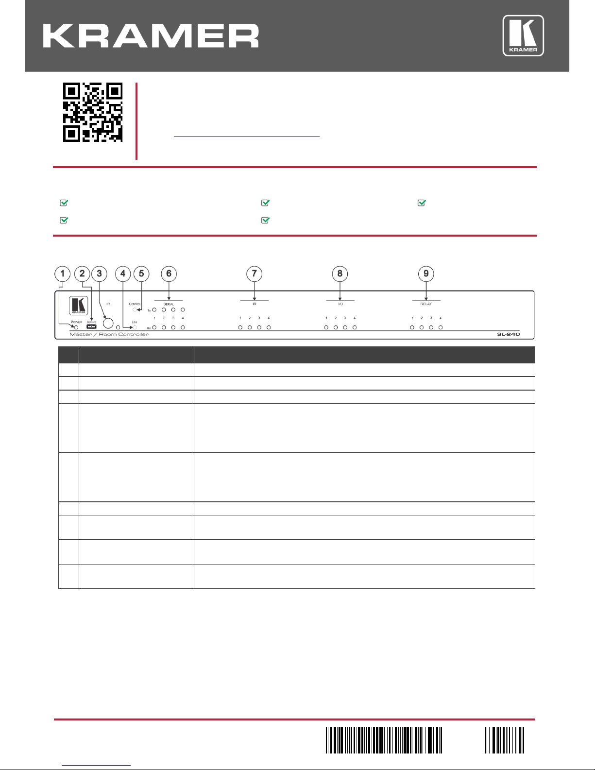
Step 2: Get to know your SL-240
# Feature Function
1
POWER LED
Lights green when powered on.
2
SERVICE Mini USB 2.0 Port
Connect to a PC to perform a firmware upgrade.
3 IR Receiver and LE D Detects IR signals for IR learning and indicates an active signal by lighting blue.
4 LINK LED Indicates Ethernet activity:
Blue LED on – good connection.
Blue LED flashing – no connection.
Blue LED off – not ready.
5 CONTROL LED Indicates control states:
Green – the control application (brain) is ready and working.
Blue – the control application ( brain) is sy nchr oniz i ng.
Red – indicates an error in the control application (brain).
6 SERIAL LEDs (from 1 to 4) White Tx LEDs and blue Rx LEDs flash to indicate activity on each channel.
7 IR LEDs (from 1 to 4) Blue LEDs indicating IR activity on each channel (the associated LED lights when the
relevant IR port transmits data).
8 I/O LEDs (from 1 to 4) Blue LEDs indicating I/O activity on each channel (the associ ated LED lig hts on Digital Out
HIGH, and when Digital In is triggered).
9 RELAY LEDs (from 1 to 4) Blue LEDs indicating relay activity on each channel (the associated LED lights when the
relay is closed).
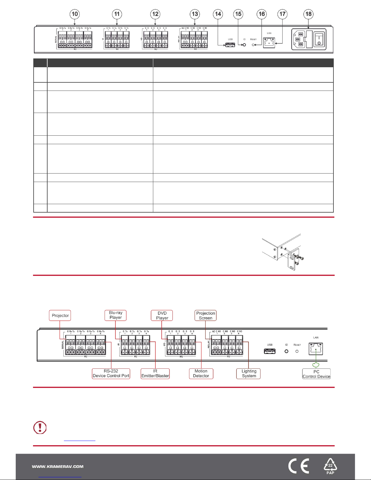
# Feature Function
10 SERIAL Ports (1-4) Terminal Block Connect to up to 4 serial contr olle d devi ces , for Ethernet-to-RS232
bidirectional tunneling.
11 IR Ports (1-4) Terminal Block Connect to up to 4 IR emitter s or blaster s.
12 I/O Ports (1-4) Terminal Block Connect to up to 4 sensors or devices to be controlled, (for example, a
motion sensor). Port may be configured as a digital input, digital output, or
analog input.
13 RELAY Ports (1-4) Terminal Block 3 NO relays and 1 NO/NC relay.
Connect to up to 4 devices to be controlled by relay (for example, a
motorized projection screen).
14 USB Connector N/A – For future use.
15 ID Button For self-identification over the network.
Press the button to send (broadcast) the Beacon P3K command.
Reply includes: IP address, UDP port number, TCP port number, MAC
address, and Model Name.
16
RESET Button
For performing a factory default reset.
17 LAN RJ-45 Connector Connects to a local area network. Indications:
LINK LED lights amber – 1000/100/10MB connection.
DATA LED flashes green – Ethernet dat a link act iv ity .
18 Power Socket with Fuse and Power Switch Connects to mains electricity, powers on and off the device.
Step 3: Install the SL-240
To rack mount the machine attach both ear brackets to the machine (by removing the three
screws from each side of the machine and replacing those screws through the ear brackets)
or place the machine on a table.
Step 4: Connect the inputs and outputs
Always switch OFF the power on each device before connecting it to your SL-240. For best results, we recommend that you always
use Kramer high-performance cables to connect AV equipment to the SL-240.
Step 5: Connect the power
Connect AC power to the rear of the SL-240, switch on its power and then switch on the power on each device.
Safety Instructions
Caution:
There are no operator serviceable parts inside the unit.
Warning:
Use only the power cord that is supplied with the unit.
Warning:
Do not open the unit. High voltages can cause electrical shock! Servicing by qualified personnel only.
Warning:
Disconnect the power and unplug the unit from the wall before installing.
See www.KramerAV.com for updated safety information.
 Loading...