

Page 1
SKIC Speaker Mounting Kit
Congratulations on purchasing your Kramer SKIC Speaker Mounting Kit which is used for
securing in-ceiling speakers to the ceiling T-channel grid and comes in three sizes: SKIC-4 for
the Galil 4-CO, SKIC-6 for the Galil 6-CO and SKIC-8 for the Galil 8-CO.
The back can speakers are supported by a C-ring and two tile rails (the tile rails prevent the
speakers from falling if the tile itself comes out or falls apart, as their ends catch onto the
T-grid). When mounting onto the ceiling tiles, use both supports. When mounting onto a
sheetrock ceiling, the C-ring alone is used to reinforce the ceiling material.
Be sure that the tiles can support the speaker. Smaller sized tiles or fiberglass-type tiles cannot
support the weight of the speakers. In such a case, the speakers will require additional support.
Each SKIC Speaker Mounting Kit includes:
Eight support ring screws, washers
and nuts
Two ceiling support rings (C-ring)
Four tile rails
Installing the Speaker Mounting Kit
The SKIC is installed after cutting the opening in the ceiling tile for the speakers.
To install the SKIC, as illustrated in the example in Figure 1, do the following:
1. Place the C-ring over the hole cut in the ceiling tile (on the “ceiling” side). Place it around
the hole so that the tabs are located in parallel to the tile edges.
Figure 1: Installing the Back Can Speakers
2. Place the tile rails on the tile and snap them into the two tabs on the C-ring.
Align the rails so that the ends extend over the T-channel grid.
3. Insert 2 screws through each tab on the C-ring to secure the rails.
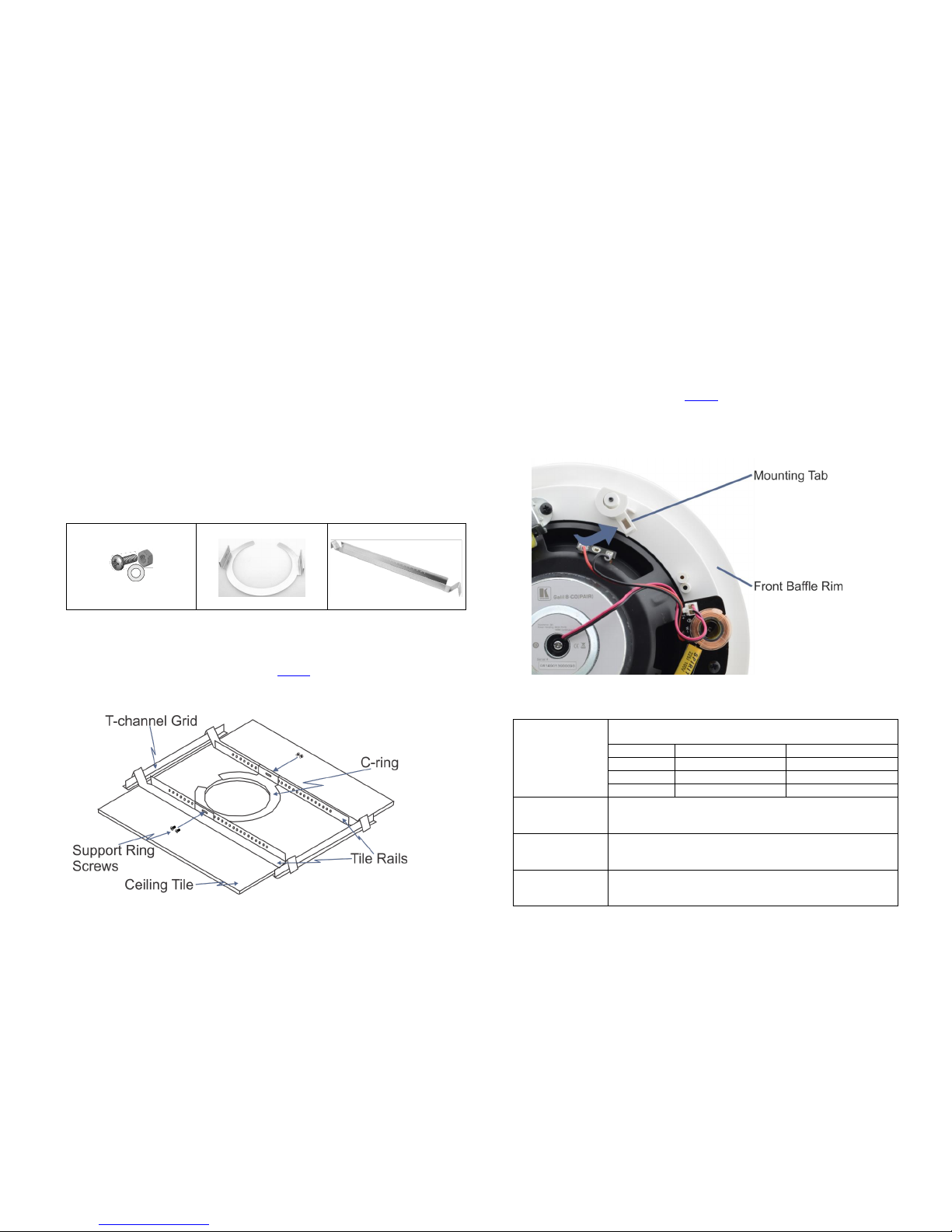
4. Push the speaker into the ceiling hole until the front baffle rim is leveled with the ceiling.
5. Tighten the mounting tabs (see Figure 2).
When tightening the mounting tabs, the tabs automatically turn outward, thus clamping
the speaker to the wall from its rear side.
Note: Do not over-tighten the mounting tabs. It may cause damage to both the speakers
and the surface.
Figure 2: Tightening the Mounting Tabs
Specifications
DIMENSIONS:
Tile rails: 64.1cm x 2.2cm x 2.3cm (25.2” x 0.87” x 0.97”) W, D, H
21.6cm x 8cm (8.5” x 3.15”)
Model
Outer Diameter
Inner Diameter
SKIC 4
18.5cm (7.28”)
14.2cm (5.6”)
SKIC 6
24.2cm (9.53”)
20cm (7.9”)
SKIC 8
28.6cm (11.3”)
24.4cm (9.6”)
DISTANCE
BETWEEN FIXING
POINTS:
SKIC 4: 19.1cm (7.5”) approx.
SKIC 6: 25.1cm (9.9”) approx.
SKIC 8: 29.5cm (11.6”) approx.
WEIGHT OF
MOUNTING KIT
(FOR PAIR):
SKIC 4: 1.03kg (2.27lbs) approx.
SKIC 6: 1.08kg (2.38lbs) approx.
SKIC 8: 1.14kg (2.51lbs) approx.
SHIPPING WEIGHT
(FOR PAIR):
SKIC 4: 1.18kg (2.6lbs) approx.
SKIC 6: 1.27kg (2.8lbs) approx.
SKIC 8: 1.36kg (3lbs) approx.
Page 2

KRAME R E L E C T R O N I C S LTD.
Installation
Instructions
MODELS:
SKIC-4 (for the Galil 4-CO)
SKIC-6 (f or the Galil 6-C O)
SKIC-8 (f or the Galil 8-C O)
Speaker Mounting Kits
For the latest information on our products and a list of Kramer
distributors, visit our Web site where updates to these installation
instructions may be found.
We welcome your questions, comments, and feedback.
Web site: www.kramerelectronics.com
E-mail: info@kramerel.com
SAFETY WARNING
Disconnect the unit from the power
supply before opening and servicing
P/N : 2 900 -3004 40 Rev 2
P/N:
2900-300440
Rev:
2
!
 Loading...