

Page 1
RC-208 Quick Start
P/N:
2900- 301199QS
Rev:
3
Scan for full manual
RC-208 Quick Start Guide
This guide helps you install and use your RC-208 for the first time.
Go to www.kramerav.com/downloads/RC-208 to download the latest user manual and check if firmware
upgrades are available.
Step 1: Check what’s in the box
RC-208 Ethernet and K-NET Control
Keypad
1 Button-cap remover
(tweezers)
Frame (or frame set) and
faceplate
1 Set of button label sheets
1 Quick start guide
8 Button caps
1 Power adapter and cord
Installation accessories
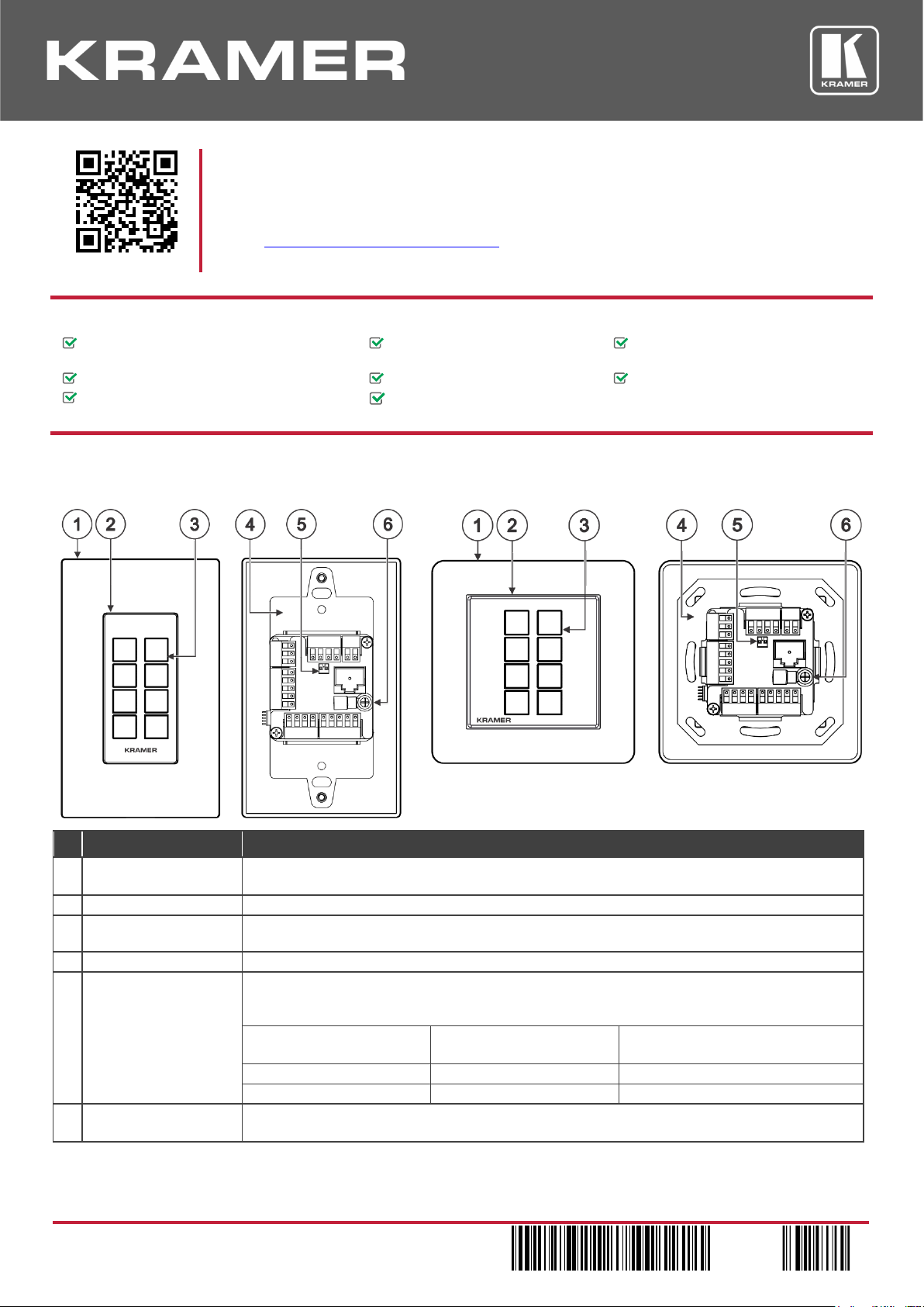
Step 2: Get to know your RC-208
US-D Version
EU/UK Version
Front
Rear
Front
Rear
#
Feature
Function
1
Designed 1 Gang Wall
Frame
For fixing the RC-208 to the wall. DECORA™ design frames are included in US-D models.
DECORA™ is a registered trademark of Leviton Manufacturing Co., Inc.
2
Button Faceplate
Covers the button area after inserting the button labels.
3
Configurable RGB
Backlit Buttons (8)
Configured to control the room and A/V devices.
Remove button covers to insert button labels (included).
4
Mounting Bracket
For fixing the frame to the in-wall box.
5 DIP-Switches
For K-NET: The last physical device on a K-NET bus must be terminated.
For RS-485: The first and the last units on the RS-485 line should be terminated. Other units
should remain unterminated.
DIP-switch 1 (to the left)
K-NET Line Termination
DIP-switch 2 (to the right)
RS-485 Line Termination
Slide down (ON)
For line termination.
For RS-485 line termination.
Slide up (OFF, default)
To leave bus unterminated.
To leave RS-485 line unterminated.
6
Ring Tongue Terminal
Grounding Screw
Connect to grounding wire (optional).
Page 2
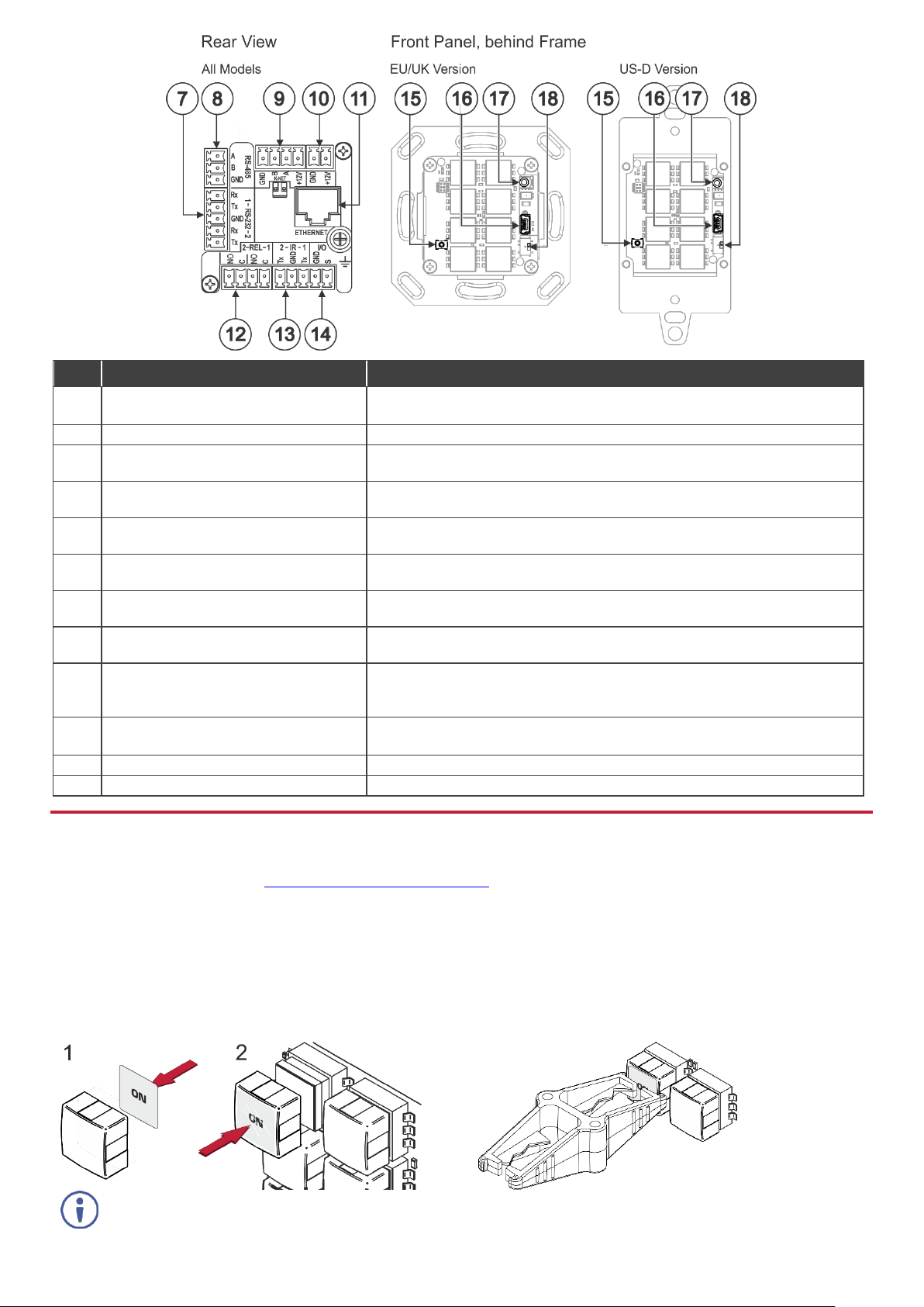
#
Feature
Function
7 RS-232 3-pin Terminal Block
Connectors (Rx, Tx, GND)
Connect to RS-232 controlled devices (1 and 2, with common GND).
8
RS-485 3-pin Terminal Block Connector
Connect to the RS-485 terminal block connector on another device or PC.
9
KNET 4-pin Terminal Block Connector
Connect the GND pin to the Ground connection; pin B (-) and pin A (+) are for
RS-485, and the +12V pin is for powering the connected unit.
10
12V Power Supply 2-pin Terminal Block
Connector (+12V, GND)
Connect to a power supply: Connect GND to GND and 12V to 12V.
11
ETHERNET RJ-45 Connector
Connect to an Ethernet LAN for control, firmware upgrade and for uploading
the configuration.
12
REL 2-pinTerminal Block Connectors
Connect to a device to be controlled by relay. For example, a motorized
projection-screen (1 and 2).
13
IR 2-pin Terminal Block Connectors
(Tx, GND)
Connect to an IR emitter cable (1 and 2, with common GND).
14
I/O 2-pinTerminal Block Connector
(S, GND)
Connect to a sensor or device to be controlled, for example, a motion sensor.
This port may be configured as a digital input, digital output, or analog input.
15
Factory Reset Button
Press while connecting the power and then release to reset the device to its
default parameters.
To access this button, you need to remove the Button Faceplate.
16
Mini USB Type B Port
Connect to your PC for firmware upgrade or for uploading the configuration.
To access the USB port, you need to remove the Button Faceplate.
17
IR Sensor
For learning commands from an IR remote control transmitter.
18
Programing DIP-switch
For internal use. Always keep set to UP (towards the mini USB port).
Step 3: Configure RC-208
To configure RC-208 buttons via K-Config:
• Configure RC-208 (go to www.kramerav.com/product/RC-208).
• Connect RC-208 to a PC via the Ethernet or connect via the mini USB port.
• Sync the configuration to RC-208.
To insert a button label for the first time:
1. Cut out the appropriate button label from the button
label sheets and place a label inside the button cover.
2. Cover with the button cap.
To replace a label:
1. Using the supplied tweezers, grip the button via the
Horizontal or vertical ledges and remove the button cap.
2. Replace the label and cover the button with the button
cap.
You do not have to detach the faceplate to remove a button.
Page 3

Step 4: Connect the inputs and outputs
Always switch OFF the power on each device before connecting it to your RC-208. For best results, we recommend
that you always use Kramer high-performance cables to connect AV equipment to RC-208.
Step 5: Install RC-208
After connecting the ports, insert the device into the in-wall box and connect the parts as shown in the illustrations
below:
EU/UK Version
Page 4

US-D Version
We recommend that you use any of the following standard 1 Gang in-wall junction boxes (or their equivalent):
• US-D: 1 Gang US electrical junction boxes.
• EU: 1 Gang in-wall junction box, with a cut-hole diameter of 68mm and depth that can fit in both the device and the
connected cables (DIN 49073).
• UK: 1 Gang in-wall junction box, 75x75mm (W, H), and depth that can fit in both the device and the connected cables
(BS 4662 or BS EN 60670-1 used with supplied spacers and screws).
Step 6: Connect the power
Connect the 12V DC power adapter to the RC-208 and plug the adapter into the mains.
Safety Instructions
Caution:
There are no operator serviceable parts inside the unit.
Warning:
Disconnect the power and unplug the unit from the wall before installing.
See www.KramerAV.com for updated safety information.
Step 7: Operate RC-208
Operate RC-208 via the front panel buttons, as a room controller keypad configured via K-Config.
 Loading...