

Page 1

Kramer Electronics, Ltd.
USER MANUAL
Models:
TP-107AVR
RC-108
RC-116, Presentation Controller
BoardView™ Kits:
Kit 2AVR: TP-107AVR (2 units) and TP-122
Kit 4AVR: TP-107AVR (4 units) and TP-122
Kit 8AVR: TP-107AVR (8 units) and TP-122
, XGA/Audio Line Transmitter
, Presentation Controller
Page 2

Contents
Contents
1 Introduction 1
2 Getting Started 2
2.1 Quick Start 2
3 Overview 4
3.1 About the TP-107AVR/TP-122 Kits 4
3.2 Controlling via the RC-108 and RC-116 Presentation Controllers 6
3.3 Shielded Twisted Pair (STP)/Unshielded Twisted Pair (UTP) 6
3.4 About the Power Connect™ Feature 6
3.5 Recommendations for Achieving the Best Performance 7
4 Your Line Transmitter, Receiver and Presentation Controllers 7
4.1 Your TP-107AVR XGA/Audio Line Transmitter 8
4.2 Your TP-122 XGA/Audio Line Receiver 9
4.3 Your RC-108/RC-116 Presentation Controller 11
5 Configuring a TP-107AVR System 13
5.1 Connecting the TP-107AVR/TP-122 Transmitter/Receiver System 13
5.2 Connecting the TP-107AVR/TP-122 BoardView™ Kit 15
5.3 Configuring the TP-107AVR/TP-122 Kit with the RC-108 16
5.4 Wiring the CAT 5 LINE IN/LINE OUT RJ-45 Connectors 17
5.5 Connecting via the K-NET™ 17
5.6 Setting the Address Number of the TP-107AVR 18
6 Controlling the TP-107AVR 19
6.1 Controlling the TP-107AVR/TP-122 Kit via the RC-108 19
6.2 Controlling the TP-107AVR/TP-122 Kit via an RS-485 Controller 19
6.2.1 RS-485 Communication Protocol 20
7 Installing a Remote Button 22
8 Flash Memory Upgrade 22
8.1 Downloading from the Internet 22
8.2 Connecting the PC to the RS-232 Port 22
8.2.1 Connecting the RC-108 to a PC via RS-232 23
8.3 Upgrading the Firmware 23
9 Technical Specifications 28
Figures
Figure 1: TP-107AVR/TP-122 Configuration 5
Figure 2: TP-107AVR XGA/Audio Line Transmitter 8
Figure 3: TP-122 XGA/Audio Line Receiver 9
Figure 4: TP-122 XGA/Audio Line Receiver (Underside) 10
Figure 5: RC-108 Presentation Controller 11
i
Page 3

Contents
Figure 6: RC-116 Presentation Controller 11
Figure 7: RC-108 Underside Panel 12
Figure 8: RC-116 Underside Panel 12
Figure 9: Connecting the XGA/Audio Line Transmitter/Receiver System 14
Figure 10: Connecting the TP-107AVR 15
Figure 11: Configuring the TP-107AVR/TP-122/RC-108 System 16
Figure 12: CAT 5 PINOUT 17
Figure 13: Wiring the RS-485 Connector 17
Figure 14: Rotary Switch Settings 18
Figure 15: Wiring to an RS-485 Controller 20
Figure 16: Connecting a PC without using a Null-Modem Adapter 23
Figure 17: Splash Screen 23
Figure 18: Atmel – Flip Window 24
Figure 19: Device Selection Window 24
Figure 20: Device Selection Window 25
Figure 21: Loading the Hex 25
Figure 22: RS-232 Window 26
Figure 23: Atmel – Flip Window (Connected) 26
Figure 24: Atmel – Flip Window (Operation Completed) 27
Tables
Table 1: Single Units 1
Table 2: BoardView™ Kit Options 1
Table 3: Connecting a Power Adapter to a System 2
Table 4: TP-107AVR XGA/Audio Line Transmitter Features 8
Table 5: TP-122 XGA/Audio Line Receiver Features 9
Table 6: TP-122 XGA/Audio Line Receiver (Underside) Features 10
Table 7: RC-108/RC-116 Presentation Controller Features 11
Table 8: RC-108/RC-116 (Underside Panel) Features 12
Table 9: CAT 5 PINOUT 17
Table 10: Rotary Switch Setting Features 18
Table 11: RS-485 Communication Protocol (Address Number 0 – 127) 21
Table 12: RS-485 Communication Protocol (Address Number 128 – 256) 21
Table 13: Remote PINOUT 22
Table 14: Technical Specifications of the TP-107AVR 28
Table 15: Technical Specifications of the RC-108/RC-116 28
ii
KRAMER: SIMPLE CREATIVE TECHNOLOGY
Page 4
Introduction
1 Introduction
Welcome to Kramer Electronics! Since 1981, Kramer Electronics has been
providing a world of unique, creative, and affordable solutions to the vast range
of problems that confront the video, audio, presentation, and broadcasting
professional on a daily basis. In recent years, we have redesigned and upgraded
most of our line, making the best even better! Our 1,000-plus different models
now appear in 11 groups
Thank you for purchasing the Kramer TP-107AVR XGA/Audio Line
Transmitter, and/or the RC-108 and/or RC-116 Presentation Controllers and/or
the BoardView™ kits (specified in Table 2
and multimedia applications.
This user manual
). The power supply is purchased separately3.
Table 2
You can purchase single TP-107AVR machines to work as standalone units or
for adding them to a BoardView™ kit, as defined in Table 1
TP-107AVR One K-NET4 and one CAT 5 cable
RC-108 One K-NET cable
RC-116 One K-NET cable
1
that are clearly defined by function.
), which are ideal for presentation
2
is supplied with each machine (see Table 1) and kit (see
:
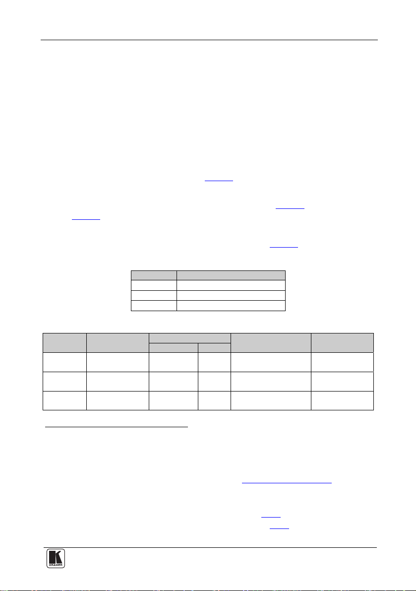
Table 1: Single Units
The unit Recommended Cables
Table 2: BoardView™ Kit Options
BoardView
Kit Name
2AVR Two TP-107AVR
4AVR Four TP-107AVR
8AVR Eight TP-107AVR
1 GROUP 1: Distribution Amplifiers; GROUP 2: Switchers and Matrix Switchers; GROUP 3: Control Systems;
GROUP 4: Format/Standards Converters; GROUP 5: Range Extenders and Repeaters; GROUP 6: Specialt y AV Products;
GROUP 7: Scan Converters and Scalers; GROUP 8: Cables and Connectors; GROUP 9: Room Connectivity;
GROUP 10: Accessories and Rack Adapters; GROUP 11: Sierra Products
2 Download up-to-date Kramer user manuals from the Internet at this URL: http://www.kramerelectronics.com
3 For single machines as well as for the BoardView™ kits
4 Kramer model BC-2T
5 The power supply is not provided with the kit, it can be purchased separately, see Table 3
6 Adding additional single units to a kit probably changes the power requirements, see Table 3
7 K-NET™ is a proprietary Kramer protocol for interconnecting Kramer units
Machines
Included
One TP-122
One TP-122
One TP-122
Recommended Cables Recommended5 Power
STP CAT 5 K-NET7
2 1 1.25A N/A
4 3 2.1A RC-108
8 7 5A RC-108/RC-116
Adapter (12V DC)6
Recommended
Controller
1
Page 5

Getting Started
Table 3: Connecting a Power Adapter to a System
The quantity of machines in a
system
Up to two TP-107AVR units 1.25A EU/US:
Three to four TP-107AVR units 2.1A EU/US:
Five to eight TP-107AVR units1 5A EU/US/UK2:
Recommended Power
Adapter (12V DC)
Part Number
UK:
Japan:
UK:
Japan:
Japan:
2 Getting Started
We recommend that you:
• Unpack the equipment carefully and save the original box and
packaging materials for possible future shipment
• Review the contents of this user manual
• Use Kramer high performance high resolution cables
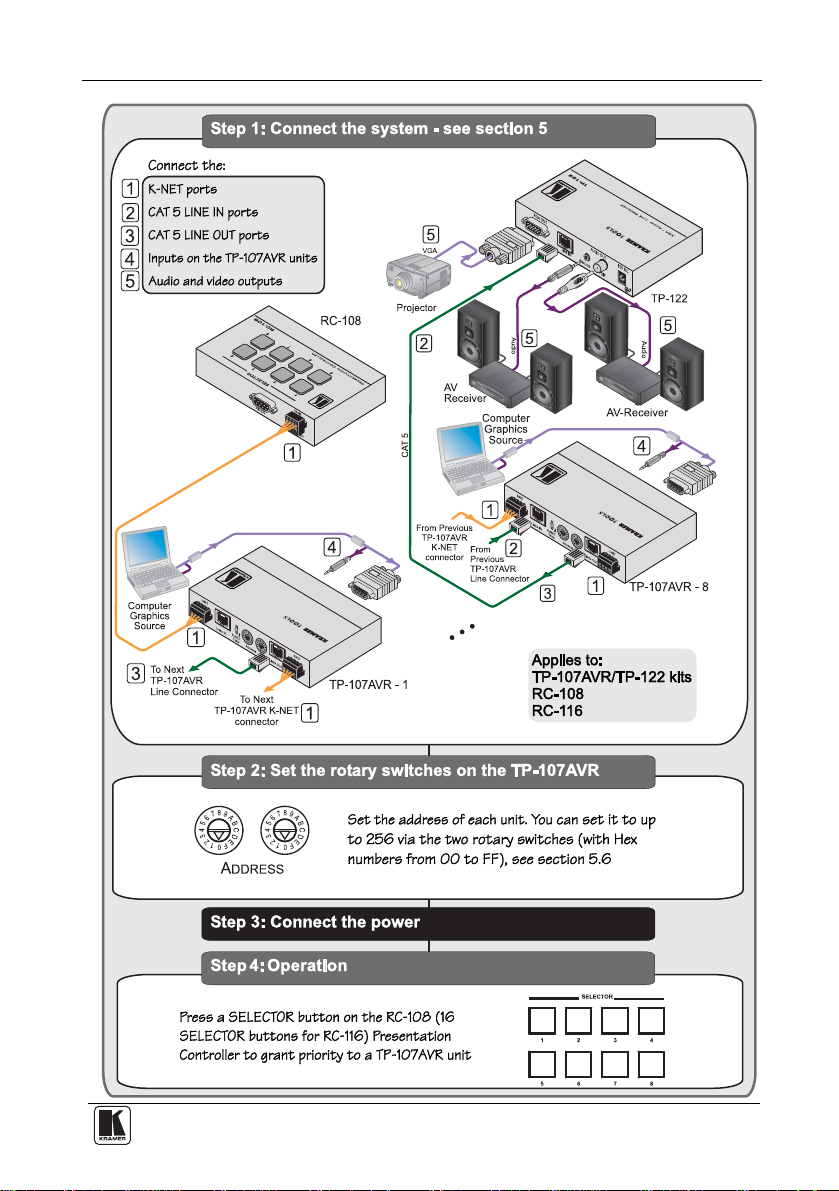
2.1 Quick Start
Thi
s quick start chart summarizes the basic setup and operation steps.
2535-000005
2535-000006
2535-700005
EU/US: 2535-000251
UK: 2535-025121
Japan: 2535-700251
2535-000635
2535-700635
3
1 If more than eight units are used, it is recommended to connect two 5A power adapters to the system
2 A desktop power supply with a DC plug. This power supply requires an AC power cord; use the power cables with a US
plug for the US, an EU plug for Europe, and a UK plug for the UK
3 The complete list of Kramer cables is on our Web site at http://www.kramerelectronics.com
2
KRAMER: SIMPLE CREATIVE TECHNOLOGY
Page 6
Getting Started
3
Page 7

Overview
3 Overview
This section describes:
• The TP-107AVR/TP-122 BoardView™ kits, see section 3.1
• The RC-108 and the RC-116, presentation controllers, see section 3.2
• Using shielded twisted pair (STP)/unshielded twisted pair (UTP), see
section 3.3
• The Power Connect™ feature, see section 3.4
• Recommendations for achieving the best performance, see section 3.5
3.1 About the TP-107AVR/TP-122 Kits
The TP-
computer graphics
107AVR is an XGA/Audio Line Transmitter that accepts a
1
video signal and an analog audio signal and transmits
them over a CAT 5 cable.
The TP-122 is an XGA/Audio Line Receiver
2
that receives the coded CAT 5
signal transmitted by a TP-107AVR decodes it and converts it to XGA,
stereo analog and S/PDIF digital audio outputs.
You can use a single TP-107AVR unit together with the TP-122 to
configure an XGA/Audio Line to Twisted Pair Transmitter and Receiver
system.
3
The BoardView™ kits include two, four or eight
can be interconnected (via CAT 5 and K-NET™ cables) and each assigned
an address number
4
. Pressing an ONLINE button on any of the
TP-107AVR units that
interconnected machines transmits the signal from that machine to the
TP-122 receiver, which is also connected to the system (see Figure 1
). The
signal is then decoded on the TP-122 and converted to an XGA output and
audio outputs. If the ONLINE button is pressed simultaneously on several
machines, the machine with the highest address number transmits the signal
to the receiver (for example, address number 5 has priority over address
number 1).
If a controller (for example, the RC-108/RC-116 Presentation Controller, see
section 3.2
) is connected to the BoardView™ kit, it can be used to determine
which machine in the chain has access to the TP-122.
1 The terminology XGA is used throughout this manual. This implies an y RGBHV signal on a 15-pin HD computer graphics
video connector having a resolution from VGA up to and including UXGA
2 You can download the Kramer TP-122 user manual at: http://www.kramerelectronics.com
3 Single TP-107AVR units can be added to a kit (up 16 units in a chain)
4 A priority number
4
KRAMER: SIMPLE CREATIVE TECHNOLOGY
Page 8
Overview
Figure 1: TP-107AVR/TP-122 Configuration
The TP-107AVR includes:
• A LINE IN CAT 5 connector, that connects to the LINE OUT CAT 5
connector on the previous Line Transmitter
• A LINE OUT CAT 5 connector, that connects to a receiver (for
example, the TP-122) or to the next Line Transmitter in the chain
• A pair of rotary selector switches for setting the ADDRESS (see
section 5.6
)
In addition, the TP-107AVR:
• Must be controlled via KNET
• Has a resolution of up to UXGA
• Is 12V DC fed
The TP-122:
• Can power—or be powered by—the transmitter over the same CAT 5
cable (see section 3.4
)
• Can change the polarity of decoding H and V Sync for video
• Includes EQ. and level controls
• Allows an operation range of more than 3 00ft (more than 100m) over
standard CAT 5 cable
• Is 12V DC fed
5
Page 9

Overview
3.2 Controlling via the RC-108 and RC-116 Presentation Controllers
The RC-108 and RC-116 are presentation controllers designed specifically to
control a BoardView™ system
appropriate number of input selector buttons
1
. Each presentation controller has the
2
, an RS-485 and 12V DC port
and an RS-232 9-pin D-sub port for firmware upgrade.
3.3 Shielded Twisted Pair (STP)/Unshielded Twisted Pair (UTP)
recommend that you use Shielded Twisted Pair (STP) cable. There are
We
different levels of STP cable available, and we advise you to use the best
quality STP cable that you can afford. Our non-skew-free cable, Kramer
BC-STP is intended for analog signals where skewing is not an issue. For
cases where there is skewing, our UTP skew-free cable, Kramer BC-XTP,
may be used. Bear in mind, though, that we advise using STP cables where
possible, since the compliance to electromagnetic interference was tested
using those cables.
Although Unshielded Twisted Pair (UTP) cable might be preferred for long
range applications, the UTP cable should be installed far away from electric
cables, motors and so on, which are prone to cre ate electrical interference.
However, since the use of UTP cable might cause inconform ity to
electromagnetic standards, Kramer does not commit to meeting the standard
with UTP cable.
3.4 About the Power Connect™ Feature
Power Connect feature applies as long as the cable can carry power.
The
This feature is available when using STP cable and the distance does not
exceed 50m on standard CAT 5 cable. For longer distances, heavy gauge
cable should be used
3
. For units which are connected via RJ-45 connectors,
make sure that the shield of the STP cable is connected to the metal casing
of the connectors on both ends of the cable. For units which are connected
via terminal block connectors, the shield of the STP cable must be
connected to a ground terminal on the units at both ends (use the ground
terminal of the power supply connection if necessary).
For a CAT 5 cable exceeding a distance of 50m, separate power suppli es
should be connected to the transmitter and to the receiver simultaneously.
1 Up to eight and up to 16 units, respectively
2 Eight and 16 buttons, respectively
3 CAT 5 cable is still suitable for the video/audio transmission, but not for feeding the power at these distances
6
KRAMER: SIMPLE CREATIVE TECHNOLOGY
Page 10

Your Line Transmitter, Receiver and Presentation Controllers
3.5 Recommendations for Achieving the Best Performance
To achieve the best performance:
• Use only good quality connection cables
1
to avoid interference,
deterioration in signal quality due to poor matching, and elevated noise
levels (often associated with low quality cables).
• Avoid interference from neighboring electrical appliances that may
adversely influence signal quality and position your Kramer product
away from moisture, excessive sunlight and dust
4 Your Line Transmitter, Receiver and Presentation
Controllers
This section defines the:
• TP-107AVR XGA/Audio Line Transmitter (see section 4.1
• TP-122 XGA/Audio Line Receiver (see section 4.2
)
)
• RC-108 and RC-116 Presentation Controllers (see section 4.3
)
1 Available from Kramer Electronics on our Web site at http://www.kramerelectronics.com
7
Page 11

Your Line Transmitter, Receiver and Presentation Controllers
4.1 Your TP-107AVR XGA/Audio Line Transmitter
Figure 2
and Table 4 define the TP-107AV R:
Figure 2: TP-107AVR XGA/Audio Line Transmitter
Table 4: TP-107AVR XGA/Audio Line Transmitter Features
# Feature Function
1 K-NET Terminal Block
Connector
2 LINE OUT RJ-45 Connector Connects to2 the LINE IN RJ-45 connector on the receiver3 or the
3 ADDRESS Selectors Rotate to select the address number4
4
5 K-NET TERM Switch
6 LINE IN RJ-45 Connector Connects to2 the LINE OUT RJ-45 connector on the previous line
7 K-NET Terminal Block
Connector
8 XGA IN 15-pin HD Connector Connects to the XGA source
9 Audio IN 3.5mm Mini Jack Connects to the audio source
10 Remote 3.5mm Mini Jack Connect to an external button for easy on-line connection (for
11 ONLINE Button Press to access priority
12 ONLINE LED Lights when gaining priority
13 ON LED Lights when receiving power
Connect to the previo u s o r n ext line transm i t t er or to a co n trol d evice .
GND is for the ground connection; B (-) and A (+) are for RS-485,
and +12V is for powering the unit
next line transmitter
Set the switch to ON to terminate the K-NET line with 120Ω
transmitter
Connect to the previo u s o r n ext line transm i t t er or to a co n trol d evice .
GND is for the ground connection; B (-) and A (+) are for RS-485,
and +12V is for powering the unit
example, when the unit is installed under the table). For the pinout,
see section 7
1
1
1 The 12V DC power supply (not provided) is used to power the system (see Table 2)
2 Using CAT 5 cable with RJ-45 connectors at both ends (the PINOUT is defined in Table 9
3 For example, the Kramer TP-122. You can download this user manual at: http://www.kramerelectronics.com
4 From 1 to 256 (see section 5.6
8
)
KRAMER: SIMPLE CREATIVE TECHNOLOGY
and Figure 12)
Page 12

Your Line Transmitter, Receiver and Presentation Controllers
4.2 Your TP-122 XGA/Audio Line Receiver
Figure 3
and Table 5 define the TP-122 XGA/Audio Line Receiver:
Figure 3: TP-122 XGA/Audio Line Receiver
Table 5: TP-122 XGA/Audio Line Receiver Features
# Feature Function
1
12V DC
2
3 ANALOG 3.5mm Mini
4 LINE IN RJ-45 Connector Connects to1 LINE OUT RJ-45 connector on the TP-107AVR
5 XGA OU T 15-pin HD Connector Connects to the XGA acceptor
6 LINK LED Illuminates when receiving the correct input signal
7 LEVEL Trimmer Adjusts3 the output signal level
8 EQ.2 Trimmer Adjusts3 the cable compensation equalization level
9 ON LED Illuminates when receiving power
S/PDIF RCA connector Connects to the digital audio acceptor
OUT
AUDIO
Jack
+12V DC connector for powering the unit
Connects to the analog audio acceptor
1 Using an STP CAT 5 cable with RJ-45 connectors at both ends (the PINOUT is defined in Table 9 and Figure 12)
2 Degradation and VGA/XGA signal loss can result from using long c ables (due to stray capacitance), sometimes leading to a
total loss of sharpness in high-resolution signals
3 Use a screwdriver to carefully rotate the trimmer, adjusting the appropriate level
9
Page 13

Your Line Transmitter, Receiver and Presentation Controllers
Figure 4 and Table 6 define the underside of the TP-122 XGA/Audio Line
Receiver:
Figure 4: TP-122 XGA/Audio Line Receiver (Underside)
Table 6: TP-122 XGA/Audio Line Receiver (Underside) Features
# Feature Function
1 VS Switch Slide the switch down, to set the V SYNC to negative polarity; slide the switch up1,
2 HS Switch Slide the switch down, to set the H SYNC to negative polarity; slide the switch up1,
to set the V SYNC to positive polarity
to set the H SYNC to positive polarity
1 By default, both switches are set down (for a negative V SYNC and H SYNC polarity)
10
KRAMER: SIMPLE CREATIVE TECHNOLOGY
Page 14

Your Line Transmitter, Receiver and Presentation Controllers
4.3 Your RC-108/RC-116 Presentation Controller
Figure 5
and Table 7 define the RC-108:
Figure 5: RC-108 Presentation Controller
Figure 6 and Table 7 define the RC-116:
Figure 6: RC-116 Presentation Controller
Table 7: RC-108/RC-116 Presentation Controller Features
# Feature Function
1 SELECTOR Buttons1 Press to give priority to a TP-107AVR unit, according to its address
2 RS-232 9-pin D-sub Connector Connects to a PC for upgrading the firmware
3 RS-485 and 12V DC PINs GND is for the ground connection; B (-) and A (+) are for RS-485,
number
Press and hold
TP-107AVR and regaining control
and +12V is for powering the unit
2
to toggle between releasing control3 over the
1 From 1 to 8 for the RC-108, and from 1 to 16 for the RC-116
2 For about 2 seconds
3 For example, to let unit 6 gain control, press the selector button 6 (button 6 illuminates). To let unit 7 gain control, press the
selector button 7 (button 7 illuminates and button 6 no longer illuminates). To release control over the units, press and hold
the selected button (button 7 in this example) until it no longer illuminates
11
Page 15

Your Line Transmitter, Receiver and Presentation Controllers
Figure 7 and Figure 8 illustrate the underside of the RC-108 and the
RC-116, respectively, as defined in Table 8
:
Figure 7: RC-108 Underside Panel
Figure 8: RC-116 Underside Panel
Table 8: RC-108/RC-116 (Underside Panel) Features
# Feature Function
1 PROGRAM Switch Slide downwards for normal operation, slide upwards to PROGRAM to
2 RS-485 TERM. Switch
3
NULL MODEM MODE
Switch
upgrade to the latest Kramer firmware (see
Slide the switch downwards to terminate the RS-485 Line with 120Ω
To connect a PC to the unit using a null-modem adapter, slide the NULL
MODEM MODE switch downwards, otherwise connect without a nullmodem adapter
section 8),
12
KRAMER: SIMPLE CREATIVE TECHNOLOGY
Page 16

Configuring a TP-107AVR System
5 Configuring a TP-107AVR System
This section describes how to:
• Connect the TP-107AVR (see section 5.1
• Configure a TP-107AVR/TP-122 BoardView™ kit (see section 5.2
• Connect the RC-108/RC-116 Presentation Controller to the
BoardView™ kit (see section 5.3
)
• Wire the CAT 5 LINE IN/LINE OUT RJ-45 connectors (see section
)
5.4
• Connect via the K-NET terminal block connector (see section 5.5
• Set the address number (see section 5.6
5.1 Connecting the TP-107AVR/TP-122 Transmitter/Receiv er
Sy
stem
To connect the TP-107AVR XGA/Audio Line Transmitter with the TP-122
XGA/Audio Line Receiver, as the example in Figure 9
following:
1. On the TP-107AVR, connect an XGA source (for example, a computer
graphics source) to the XGA IN 15-pin H D computer graphics c onnector
and an audio source to the audio IN 3.5mm mini jack, for exa mple, using a
Kramer C-GMA/GMA cable (VGA 15-pin HD (M ) + audio jack to VG A
15-pin HD (M) + audio jack)
1
.
2. On the TP-122, connect the XGA OUT 15-pin HD (F) co nnector to the
XGA acceptor (for example, a display), and connect the AUDIO OUT
S/PDIF RCA connector to the digital audio acce ptor (for example, an AV
receiver), and the ANALOG 3.5mm mini jack to the analog audio acceptor
(for example, a stereo audio recorder).
3. Connect the LINE OUTP UT RJ-45 co nnector on t he TP-107AVR to the
LINE IN RJ-45 connector on the TP-122, via STP cabling
up to 300ft (100m)), see section 5.4
.
4. Connect a 12V DC power supply to each power socket on t he TP-107AVR
and the TP-122, and connect the powe r supplies to the m ains electricity.
The signal from the XGA source is transmitted via CAT 5 cable, decoded
and converted at the XGA OUT 15-pin HD (F) connector t o the XGA
acceptor.
1 Not supplied. The full list of Kramer cables is on our Web site at http://www.kramerelectronics.com. Alternativel y, you can
connect an XGA source to the XGA IN 15-pin HD computer graphics connector, and a sep arate audio source to the AUDIO
IN 3.5mm mini jack
2 The Kramer BC-STP cable is recommended
)
)
)
)
illustrates, do the
2
(with a range of
13
Page 17

Configuring a TP-107AVR System
5. On the TP-122:
Adjust
1
the video output signal level and/or cable compensation
equalization level, if required
If necessary, set the H SYNC and V SYNC switches
underside
2
on the
Figure 9: Connecting the XGA/Audio Line Transmitter/Receiver System
1 Use a screwdriver to carefully rotate the trimmer, adjusting the appropriate level
2 By default, both switches are set down (for negative V SYNC and H SYNC polarity)
14
KRAMER: SIMPLE CREATIVE TECHNOLOGY
Page 18

Configuring a TP-107AVR System
5.2 Connecting the TP-107AVR/TP-122 BoardView™ Kit
To connect the TP-107AVR/TP-122 BoardView™ kit as illustrated in the
example in Figure 10
, do the following:
1. Connect an XGA source (for example, a computer graphics source) to the
XGA IN 15-pin HD computer graphics connector and an audio source to
the audio IN 3.5mm mini jac k, for ex ample, usin g a Kram er
C-GMA/GMA cable (VGA 15-pin HD (M) + audio jack to VGA 15-pin
HD (M) + audio jack)
2. Connect the LINE OUT RJ-45
1
.
2
connector to the LINE IN RJ-45
connector on the next TP-107AVR in the chain or to the LINE IN RJ-45
connector of a receiver (for example, the Kramer TP-122), via STP
3
cabling
. The total range of the connected units should be no more than
300ft (100m).
3. Connect the LINE OUT RJ-45 connector of the previous TP-107AVR unit
to the LINE IN RJ-45 connect or on the TP-107AVR.
4
4. Connect the K-NET
to the RC-108 Presentation Controller
port to the previous and t he next TP-107AVR unit or
5
.
5. Set an address number for each TP-107AVR unit via the two
potentiometers (see section 5.6
6. Connect the 12V DC power supply (see Table 3
).
) to the power socket and
connect the power supply to the mains electricity.
Figure 10: Connecting the TP-107AVR
1 Not supplied. The full list of Kramer cables is on our Web site at http://www.kramerelectronics.com. Alternativel y, you can
connect an XGA source to the XGA IN 15-pin HD computer graphics connector, and a sep arate audio source to the AUDIO
IN 3.5mm mini jack
2 For details of how to wire a CAT 5 LINE IN/LINE OUT RJ-45 connector, see section 5.4
3 The Kramer BC-STP cable is recommended
4 The 12V DC power supply (provided) is used to power the system (see Table 2
5 Or alternatively to the RC-116 (see section 3.2
)
)
15
Page 19

Configuring a TP-107AVR System
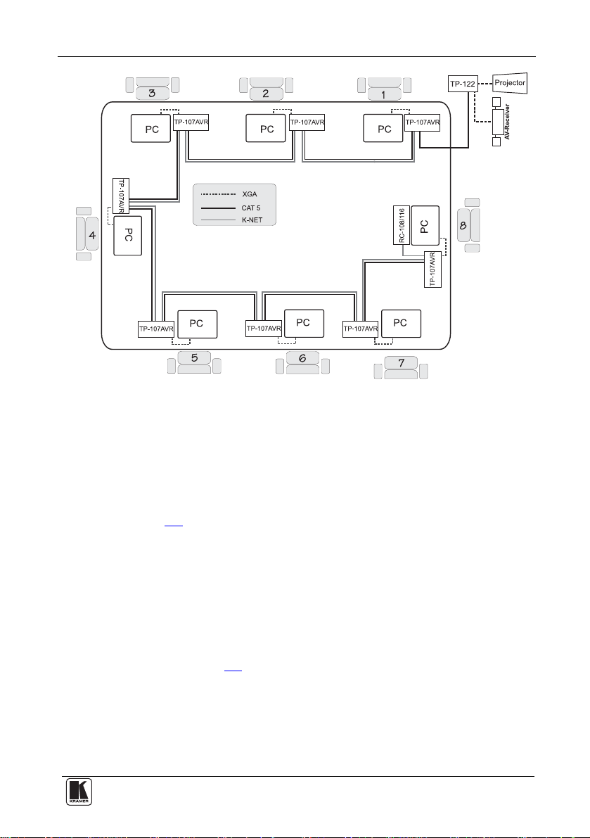
5.3 Configuring the TP-107AVR/TP-122 Kit with the RC-1081
To configure a presentation system as illustrated in the example in Figure 11
do the following:
1. Connect the computer graphics source on eac h TP-107AVR machine in the
chain (see section 5.1
).
2. Interconnect the TP-107AVR machines via the CAT 5 and K-NET cables.
3. Connect the RC-108 Presentation Controller to the chain via the K-NET
4. Connect the last TP-107AVR unit to a receiver (for example, the Kramer
2
.
port
TP-122
3
), which is connected to an acceptor (for example, a projector and
an AV receiver with speakers).
5. Set the RS-485 TERM switch on the first and the last unit to ON.
6. Set an address number for each TP-107AVR unit via the two rotary
switches (see section 5.6
).
,
Figure 11: Configuring the TP-107AVR/TP-122/RC-108 System
1 From this section on, the RC-108 applies also to the RC-116, unless stated otherwise
2 RS-485 on RC-108
3 Refer to the separate user manual, which can be downloaded at http://www.kramerelectronics.com
16
KRAMER: SIMPLE CREATIVE TECHNOLOGY
Page 20

Configuring a TP-107AVR System
5.4 Wiring the CAT 5 LINE IN/LINE OUT RJ-45 Connectors
Table 9
and Figure 12 define the STP CAT 5 PINOUT, using a straight
pin-to-pin cable with RJ-45 connectors:
Table 9: CAT 5 PINOUT
EIA /TIA 568A EIA /TIA 568B
PIN Wire Co lor PIN Wire Color
1 Green/White 1 Orange/White
2 Green 2 Orange
3 Orange/White 3 Green/White
4 Blue 4 Blue
5 Blue/White 5 Blue/White
6 Orange 6 Green
7 Brown/White 7 Brown/White
8 Brown 8 Brown
Pair 1 4 and 5 Pair 1 4 and 5
Pair 2 3 and 6 Pair 2 1 and 2
Pair 3 1 and 2 Pair 3 3 and 6
Pair 4 7 and 8 Pair 4 7 and 8
Figure 12: CAT 5 PINOUT
5.5 Connecting via the K-NET™
The TP-107AVR units connect to the RC-108/RC-116 controller via the
K-NET ports, as illustrated in Figure 13
.
K-NET PINOUT
GND
-
B
+
A
+12V
Black
White
Green
Red
Figure 13: Wiring the RS-485 Connector
17
Page 21

Configuring a TP-107AVR System
5.6 Setting the Address Number of the TP-107AVR
A maximum of 256 addresses can be set via the two rotary switches
each Hex number ranging from 0 to F). When using the Kramer RC-108 or
RC-116 controller, the address numbers are set from 1 to 8 or from 1 to 16
respectively
controller), as illustrated in Figure 14
2
(in accordance with the numbers on the rotary switches on the
and defined in Table 10.
1
(with
0
1
F
2
E
3
D
4
C
5
B
6
A
7
9
8
0
1
F
2
E
3
D
4
C
5
B
6
A
7
9
8
Figure 14: Rotary Switch Settings
Table 10: Rotary Switch Setting Features
Address # Left Right Address # Left Right
1 0 0 9 0 8
2 0 1 10 0 9
3 0 2 11 0 A
4 0 3 12 0 B
5 0 4 13 0 C
6 0 5 14 0 D
7 0 6 15 0 E
8 0 7 16 0 F
0
1
F
E
D
C
B
A
9
8
0
1
F
2
3
6
7
2
E
3
D
4
5
4
C
5
B
6
A
7
9
8
0
1
F
E
D
C
B
A
7
9
8
0
1
F
2
3
4
5
6
2
E
3
D
4
C
5
B
6
A
7
9
8
The option to set the address numbers up to 256 is useful when preparing
meetings, for example, in hotels or conference centers. When one
conference center uses many TP-107AVR units (for example, 32 units),
preset each to a different address number (any number from 1 to 256). The
preset addresses make it easy to setup a BoardView™ system. For example,
to setup a 16-unit system, take any of the available machines and connect
them (as described in section 5.5
about a duplicate address number. Such a system can be used without
connecting the RC-108/RC-116 Presentation Controller
) in any order without having to worry
3
, letting each
participant in the meeting gain access by pressing the ONLINE button.
1 To maintain high quality video transmission, using more than 16 units in a system is not recommended
2 For higher address numbers refer to a decimal to Hex converter. For example, address number 125 is 7D
3 To use the RC-108/RC-116, the address numbers on the TP-107AVR units must be set from 1 to 8/1 to 16, respectively
18
KRAMER: SIMPLE CREATIVE TECHNOLOGY
Page 22

Controlling the TP-107AVR
6 Controlling the TP-107AVR
The TP-107AVR can be used in a transmitter and receiver system as
described in section 3.1
in section 5.6
).
, or set up as a controller-less system (see example
You can use the RC-108/RC-116 (see section 6.1
based controller
1
to control the BoardView™ system (see section 6.2).
) or any other RS-485
6.1 Controlling the TP-107AVR/TP-122 Kit via the RC-108
The RC
-108 unit, when connected to a chain of TP-107AVR units, controls
the system by granting access to the projector and overriding the individual
ONLINE buttons on the TP-107AVR units.
If a SELECTOR button on the RC-108 is pressed and held for about two
seconds, the RC-108 loses control over the TP-107AVR units in the chain.
To regain control, press and hold once again.
6.2 Controlling the TP-107AVR/TP-122 Kit via an RS-485 Controller
o control a BoardView™ via an RS-485 controller (see to section 6.2.1
T
the RS-485 communication Protocol), for example, the Kramer RC-8IR
for
2
Room Controller, connect the chain of TP-107AVR units to the RS-485
terminal blocks (see Figure 15
).
1 For example, the Kramer RC-8IR Room Controller
2 Refer to the separate user manual, which can be downloaded at http://www.kramerelectronics.com
19
Page 23

Controlling the TP-107AVR
K-NET PINOUT
GND
-
B
+
A
+12V
Black
White
Green
Red
Power
Supply
TM
Power
Supply
For the RC-8IR
For the BoardView
System (see Table 3)
Figure 15: Wiring to an RS-485 Controller
You can also connect the same power supply to the BoardView™ System
and the RC-8IR (see Table 3
6.2.1 RS-485 Communication Protocol
)
Use the communication protocol to control the TP-107AVR units via an
RS-485 controller. The communication settings are: 9600 bps, 8 data bits,
no parity, 1 stop bit and no flow control.
Table 11
20
defines the communication protocol for address numbers 0 to 127.
KRAMER: SIMPLE CREATIVE TECHNOLOGY
Page 24
Controlling the TP-107AVR
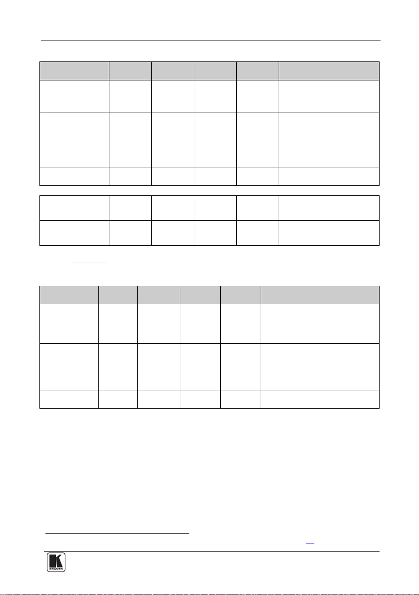
Table 11: RS-485 Communication Protocol (Address Number 0 – 127)
Command: Command 1 Command 2 Command 3 Command
Select a TP-107AVR
machine according to
its address number
Free Speech
Turn OFF a
TP-107AVR
The TP-107AVR replies:
In Free Speech mode
the ONLINE button is
ON
In Free Speech mode
the ONLINE button is
OFF
H02 H81 H80 +
Address
H02 H82 H80 +
Address
H02 H83 H80 +
Address
H05 H81 H80 +Addr H81
H05 H80 H80 +Addr H81
H81
1
H81
1
H81
1
4
Description:
The VGA input of the selected
TP-107AVR device is activated.
VGA inputs of other TP-107AVR
units in the chain are blocked
Following this command, any
TP-107AVR in the chain can be
activated by pressing the ONLINE
button. This state is cancelled after
the "Select TP-107AVR Machine"
command is sent to any
TP-107AVR in the chain
The VGA input of the selected
TP-107AVR device is blocked
Reply sent from the specific TP107AVR to the controller
Reply sent from the specific TP107AVR to the controller
Table 12 defines the Communication protocol for address numbers 0 to 127
Table 12: RS-485 Communication Protocol (Address Number 128 – 256)
Command: Command 1 Command 2 Command 3 Command
Select a
TP-107AVR
machine according
to its address
number
Free Speech
Turn OFF a
TP-107AVR
H02 H81 Address1 HC1
H02 H82 Address1 HC1
H02 H83 Address1 HC1
4
The VGA input of the selected
TP-107AVR device is activated.
VGA inputs of other TP-107AVR units in
the chain are blocked
Following this command, any TP-107AVR
in the chain can be activated by pressing
the ONLINE button. This state is
cancelled after the "Select TP-107AVR
Machine" command is sent to any
TP-107AVR in the chain
The VGA input of the selected
TP-107AVR device is blocked
Description:
For example:
• Select TP-107AVR machine 5:
Hx02,Hx81,Hx85,Hx81
• Select TP-107AVR machine 200 (HxC8):
Hx02,Hx81,HxC8,HxC1
• Select TP-107AVR machine 100 (Hx64):
Hx02,Hx81,HxE4,Hx81
Calculation – Hx80+Hx64 = HxE4
1 The address number of the selected TP-107AVR as set by the rotary address switches (see section 5.6)
21
Page 25

Installing a Remote Button
7 Installing a Remote Button
You can connect the remote 3.5mm mini jack to an external button for easy
on-line connection when the unit is installed, say, under the table. Table 13
defines the remote pinout:
Table 13: Remote PINOUT
PIN Function
Left LED
L
R
Gnd
Right Key switch
Gnd Ground
8 Flash Memory Upgrade
The RC-1081 firmware is located in FLASH memory, which lets you
upgrade
2
to the latest Kramer firmware version in minutes! The process
involves:
• Downloading from the Internet (see section 8.1
• Connecting the PC to the RS-232 port (see section 8.2
• Upgrading firmware (see section 8.3
8.1 Downloading from the In
You can download the up-to-date file
1. Go to our Web site at www.kra
ternet
)
3
from the Internet. To do so:
merelectronics.com and download the file:
)
)
“FLIP_RC108.zip” from the Technical Support section.
2. Extract the file: “FLIP_ RC108.zip” to a folder (for exam ple, C:\Program
Files\Kramer Flash).
3. Create a shortcut on your desktop to the file: “FLIP.EXE”.
8.2 Connecting the PC to the RS-232 Port
Before in
stalling the latest Kramer firmware version on a RC-108 unit, do
the following:
1. Connect the RS-232 9-pin D-sub side panel port (see section 8.2.1
).
2. Slide the underside PROGRAM switch to ON.
1 This section applies also to the RC-116
2 Upgrade should be carried out by skilled technical personnel. Failu re to upgrade correctl y results in the malfunction of th e
machine
3 The files indicated in this section are given as an example only. File names are liable to change from time to time
22
KRAMER: SIMPLE CREATIVE TECHNOLOGY
 Loading...