

Kramer FC-6P User Manual

USER MANUAL
MODEL:
FC-6P
Ethernet Gateway − Serial/IR
P/N: 2900-300613 Rev 1
www.kramerAV.com


FC-6P – Contents i
Contents
1 Introduction 1
2 Getting Started 2
2.1 Achieving the Best Performance 2
2.2 Safety Instructions 2
2.3 Recycling Kramer Products 3
3 Overview 4
4 Defining the FC-6P Ethernet Gateway − Serial/IR 6
5 Performing Initial Configuration 8
5.1 Configuring the FC-6P Ethernet Gateway − Serial/IR 8
5.2 Setting Up an Ethernet Connection on the PC 10
6 Connecting the FC-6P 11
6.1 Connecting via Ethernet 12
7 Remote Operation via the Web UI 17
7.1 Browsing the Web UI 17
7.2 Displaying Connected Clients 19
7.3 Setting Device Name and Time Functions 20
7.4 Setting Communication Parameters 22
7.5 Setting Serial Port Parameters 23
7.6 Configuring IR Command Learning 25
7.7 Activating Security 26
7.8 Using the Logs Page 28
7.9 Kramer Information 29
8 Using FC-6P Operations 30
8.1 IR Learning 30
8.2 Resetting to the Factory Default Settings 31
8.3 Upgrading the Firmware 31
9 Technical Specifications 32
9.1 Data Handling Performance 33
9.2 Example Bandwidth Calculation 33
10 Default Parameters 34
11 Kramer Protocol 3000 35
11.1 Kramer Protocol 3000 – Syntax 36
11.2 Kramer Protocol 3000 – Command List 39
11.3 Kramer Protocol 3000 – Detailed Commands 40

ii FC-6P - Introduction
Figures
Figure 1: FC-6P Controlled Devices from Remote IP-based Clients 5
Figure 2: FC-6P Ethernet Gateway − Serial/IR 6
Figure 3: Connecting the FC-6P for Initial Configuration 8
Figure 4: Configuring a Remote Connection 10
Figure 5: Connecting the FC-6P Ethernet Gateway − Serial/IR 11
Figure 6: Terminal Block Connections 12
Figure 7: Local Area Connection Properties Window 13
Figure 8: Internet Protocol Version 4 Properties Window 14
Figure 9: Internet Protocol Version 6 Properties Window 14
Figure 10: Internet Protocol Properties Window 15
Figure 11: General Info Page 18
Figure 12: Connected Clients Page 20
Figure 13: Device Settings Page 21
Figure 14: Communication Page 22
Figure 15: Serial Port Settings Page 23
Figure 16: Serial Port Settings Page – RS-485 24
Figure 17: Serial Port Settings Page – No Serial Ports Configured 24
Figure 18: IR Command Learner Page 25
Figure 19: Security Page 26
Figure 20: Security Confirmation Popup 26
Figure 21: Authentication Required Popup 27
Figure 22: Security Activated Page 27
Figure 23: Logs Page 28
Figure 24: About Us Page 29

FC-6P – Introduction 1
1 Introduction
Welcome to Kramer Electronics! Since 1981, Kramer Electronics has been
providing a world of unique, creative, and affordable solutions to the vast range of
problems that confront video, audio, presentation, and broadcasting professionals
on a daily basis. In recent years, we have redesigned and upgraded most of our
line, making the best even better!
Our 1,000-plus different models now appear in 14 groups that are clearly defined by
function: GROUP 1: Distribution Amplifiers; GROUP 2: Switchers and Routers;
GROUP 3: Control Systems; GROUP 4: Format/Standards Converters; GROUP 5:
Range Extenders and Repeaters; GROUP 6: Specialty AV Products; GROUP 7:
Scan Converters and Scalers; GROUP 8: Cables and Connectors; GROUP 9:
Room Connectivity; GROUP 10: Accessories and Rack Adapters; GROUP 11:
Sierra Video Products; GROUP 12: Digital Signage; GROUP 13: Audio; and
GROUP 14: Collaboration.
Congratulations on purchasing your Kramer FC-6P Ethernet Gateway − Serial/IR
that is ideal for:
• Remote IP control of RS-232 and IR controlled devices
• K-Touch multi-clients IP room control
• LAN-based expansion of K-Config control system

2 FC-6P - Getting Started
2 Getting Started
We recommend that you:
• Unpack the equipment carefully and save the original box and packaging
materials for possible future shipment
• Review the contents of this user manual
Go to www.kramerav.com/downloads/FC-6P to check for up-to-date user
manuals, application programs, and to check if firmware upgrades are
available (where appropriate).
2.1 Achieving the Best Performance
To achieve the best performance:
• For optimum range and performance, use the recommended Kramer cables
available at www.kramerav.com/product/FC-6P
• Do not secure the cables in tight bundles or roll the slack into tight coils
• Avoid interference from neighbouring electrical appliances that may adversely
influence signal quality
• Position your FC-6P away from moisture, excessive sunlight and dust
This equipment is to be used only inside a building. It may only be
connected to other equipment that is installed inside a building.
2.2 Safety Instructions
Caution:
There are no operator serviceable parts inside the unit
Warning:
Use only the Kramer Electronics power supply that is
provided with the unit
Warning:
Disconnect the power and unplug the unit from the wall
before installing

FC-6P – Getting Started 3
2.3 Recycling Kramer Products
The Waste Electrical and Electronic Equipment (WEEE) Directive 2002/96/EC aims
to reduce the amount of WEEE sent for disposal to landfill or incineration by
requiring it to be collected and recycled. To comply with the WEEE Directive,
Kramer Electronics has made arrangements with the European Advanced
Recycling Network (EARN) and will cover any costs of treatment, recycling and
recovery of waste Kramer Electronics branded equipment on arrival at the EARN
facility. For details of Kramer’s recycling arrangements in your particular country go
to our recycling pages at www.kramerav.com/support/recycling/
.

4 FC-6P - Overview
3 Overview
The FC-6P is an RS-232/IR multi-function control gateway with Power over
Ethernet, capable of plug and play deployment over a customer Ethernet LAN for
remote bidirectional RS-232 and IR emitter control of customer devices. Multiple
control clients can be IP-connected to the FC-6P control gateway for concurrent
control of two RS-232 or four IR controllable devices, such as AV scalers, video
displays, audio amplifiers, and DVD players.
This Ethernet to serial/IR gateway bridges the gap between Ethernet infrastructures
and serial or IR communication devices by offering bidirectional Ethernet to serial
and IR conversion. All setup and maintenance of the devices is done from built-in
Web pages that are accessible using any common Web browser.
The FC-6P features:
• Dual-Function I/O Ports − Remote IP-Based control of any device connected to
the control gateway dual-function I/O ports, with selectable port configuration to
bidirectional RS-232 or IR control.
• Multiple IP Connected Clients − Remotely connected over a customer Ethernet
network that concurrently controls any devices connected to control gateway
I/O ports.
• Easy & Reliable Installation:
• Plug and Play IP installation with dynamic (DHCP) address resolution
and auto device discovery over existing LAN.
• Resilient powering with USB and optional PSU (not included).
• Compact, designed for piggy-back installation, such as behind a TV or
display with the ability to draw power from device USB port and Ethernet
connectivity.
• Remote Management − Built-in web UI for remote browser-based management
and support, by multiple IP-clients over an existing LAN. Easy firmware
upgrades, either remotely via an existing LAN, or locally via device USB port.
FC-6P – Overview 5
• Power Options − USB, Power over Ethernet, optional PSU.
• PoE Support – According to IEEE 802.3af standard
• Size − DigiTOOLS™ − Mount 3 units side-by-side in a 1U rack space with the
optional RK-3T rack adapter.
Figure 1: FC-6P Controlled Devices from Remote IP-based Clients
For example, using Kramer K-Touch control software you can design advanced
room-control and automation systems that can be operated from iOS or Android
touch devices. K-Touch can be used to perform device discovery over the network
as the FC-6P is set to be a DHCP client by default.
You can use the Kramer LAN Configurator software to discover devices that are
attached to the network, including the FC-6P.
6 FC-6P - Defining the FC-6P Ethernet Gateway − Serial/IR
4 Defining the FC-6P Ethernet Gateway −
Serial/IR
This section defines the FC-6P.
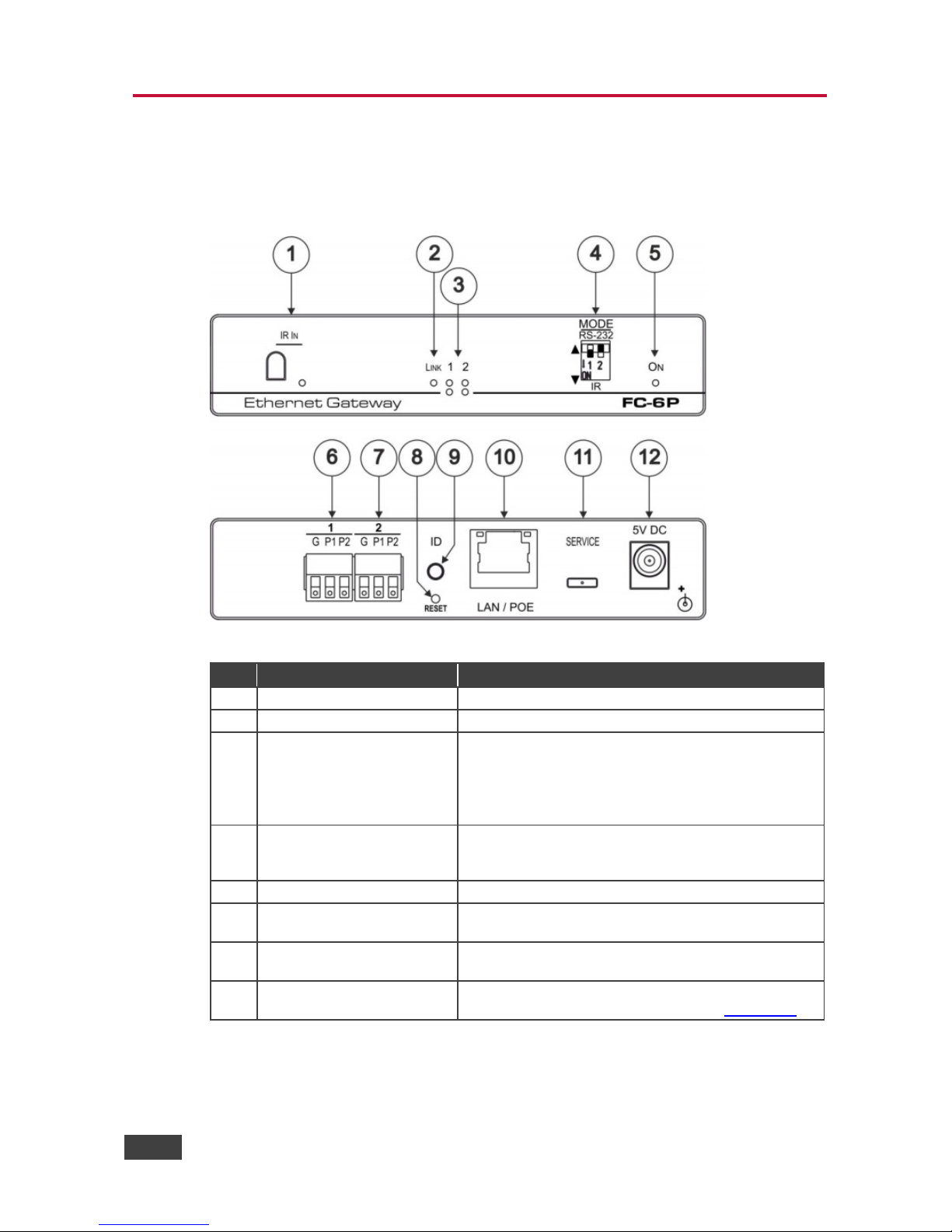
Figure 2: FC-6P Ethernet Gateway − Serial/IR
# Feature Function
1
IR Sensor
Sensor for IR learning, LED lights during activity
2
LINK LED
Shows the Ethernet link is active
3 Port 1 and 2 white (upper)
and blue LEDs
Show the transmission status of port 1 and port 2:
When set as RS-232, the white LED indicates Tx and
blue LED indicates Rx
When set as IR, the white LED indicates IR-P1 Tx
and blue LED indicates IR-P2 Tx
4 MODE DIP-switches (Port 1
and Port 2)
Switch up (off) for RS-232, switch down (on) for IR
The default setting is port 1 RS-232 (up) and port 2 IR
(down)
5
ON LED
Lights green when the unit is on
6 Port 1 I/O 3-pin Terminal
Block
Port 1 terminal block connects one bidirectional RS-
232/RS-485 port or two IR outputs
7
Port 2 I/O 3-pin Terminal
Block
Port 2 terminal block connects one bidirectional RS232 port or two IR outputs
8
RESET Button
Press and hold while cycling the device power to
reset to factory default parameters (see Section 8.2)
FC-6P – Defining the FC-6P Ethernet Gateway − Serial/IR 7
#
Feature
Function
9
ID Button
Press to broadcast ID message for auto-discovery of
the device
10
LAN/POE RJ-45 Connector
Connects to a PoE source (Power over Ethernet) for
powering and an IP client or other controller, either
directly or via a LAN (see Section 6.1)
11
SERVICE Mini USB
Connector
Connects to a USB power source for powering and to
a PC for a local firmware upgrade
12
5V DC Connector
For extra power resiliency, connect to the optional 5V
DC power supply, center pin positive. Not needed
when the device is supplied power by PoE or a USB
power source
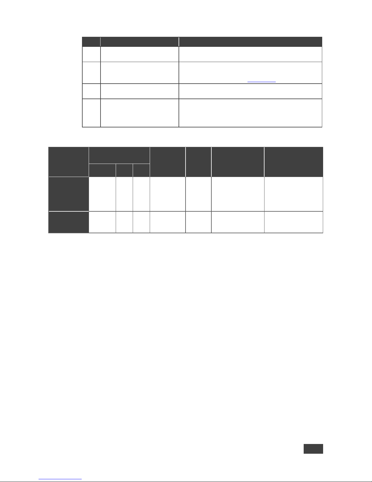
FC-6P Function Table
Port IO
Function
Terminal Block
Connections IO Port
Default
TCP
Default
Port
[P1/P2]
Blue Activity LED
Pair
Comment
G P1 P2
RS-232
Ground Rx Tx 9600,8,N,1 5001/2
Flashes when
port is
transmitting &
receiving data
Additional serial
configurations
available via Web,
including RS-485
for Port 1
IR
Ground IR1 IR2 5000
ON when ports
are transmitting
IR data
Key:
P1 / P2 – Port 1 / Port 2
Tx – Transmit, Rx– Receive
9600, 8, N, 1 – 9600 baud, 8-bits, no parity, 1 stop bit
IR
1
/ IR2 – IR Port 1 / IR Port 2
8 FC-6P - Performing Initial Configuration
5 Performing Initial Configuration
This chapter provides an overview of the initial configuration and basic operation of
the FC-6P and comprises:
• Configuring the FC-6P (see Section 5.1
)
• Configuring an Ethernet connection on the PC (see Section 5.2)
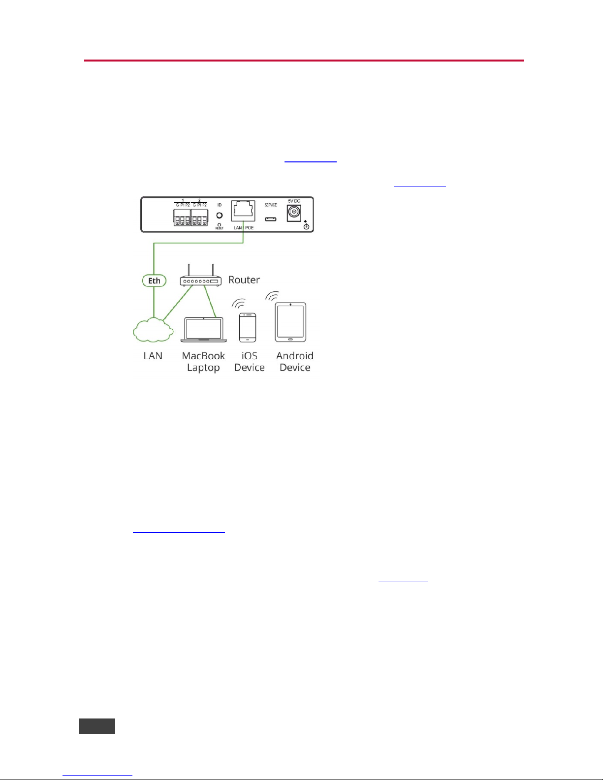
Figure 3: Connecting the FC-6P for Initial Configuration
5.1 Configuring the FC-6P Ethernet Gateway − Serial/IR
Note: The FC-6P is shipped from the factory with DHCP enabled and a random IP
address. To connect the FC-6P on first installation, you must identify the IP address
that was automatically assigned to the FC-6P. To discover the IP address of FC-6P,
use K-LAN Configurator, available for download from our website at
www.kramerav.com
.
To browse the FC-6P Web UI on taking the device out of the box (using the
default settings), use the default host name, (see Section 10
).
Use the default host name: FC-6-xxxx, where xxxx are the last four digits of the
serial number of the device.

FC-6P – Performing Initial Configuration 9
To configure the FC-6P:
1. Connect the Ethernet port on the rear panel of FC-6P to a PC, either directly
or via a LAN, (see Section 6.1
).
2. Using a Web browser and the relevant IP address, browse the General Info
home page (see Figure 11
).
3. Click on Device Settings to browse to the Device Settings page, (see
Figure 13
).
4. Enter the time and date manually, or enter the Time server address for
automatic time and date synchronization.
5. Click Save Changes.
6. Click on Communication to browse to the Communication page, (see
Figure 14
).
7. Enter the IP address, mask and gateway for static IP addressing and Click
Set. We suggest a meaningful host name.
Note: If you have changed the IP address from the default setting, you must
reload the General Info home page again using the new IP address.
8. Click on Serial Ports Settings to browse to the Serial Port Settings page,
(see Figure 15
).
9. Associate the required serial ports with their corresponding TCP/UDP
settings.
10. For each associated serial port, enter the serial port configuration
parameters using the drop-down lists under Serial Configuration.
11. Click Save Changes.
12. If required, click on Security to browse to the Security page.
13. Click ON to activate security.
The user name and password credentials popup appears.
10 FC-6P - Performing Initial Configuration
14. Enter the required user name and password. (The default user name is
Admin and the password is Admin).
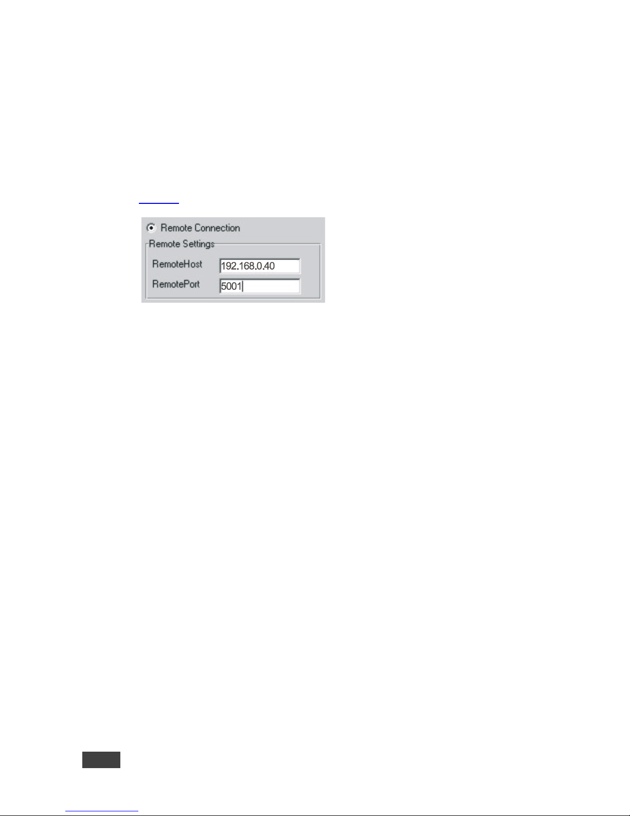
5.2 Setting Up an Ethernet Connection on the PC
If the control application can directly connect to the Ethernet driver, select the host
IP address and port number according to your FC-6P configuration, as illustrated in
Figure 4
.
Figure 4: Configuring a Remote Connection
FC-6P – Connecting the FC-6P 11
6 Connecting the FC-6P
Always switch off the power to each device before connecting it to your
FC-6P. After connecting your FC-6P, connect its power and then switch
on the power to each device.
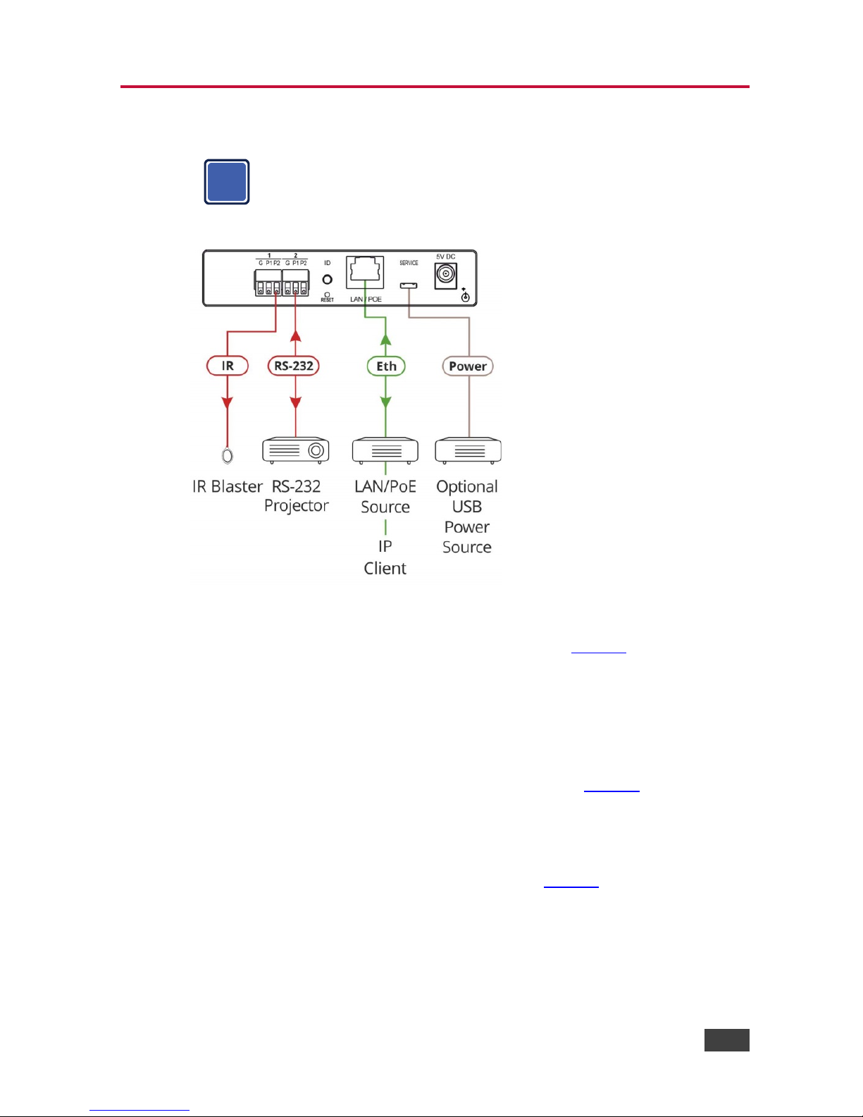
Figure 5: Connecting the FC-6P Ethernet Gateway − Serial/IR
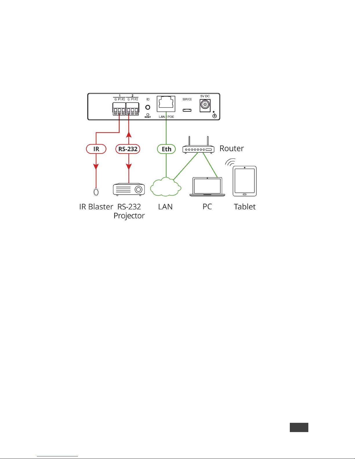
To connect the FC-6P as illustrated in the example in Figure 5:
1. Connect the device to a LAN or PC via the RJ-45 Ethernet connector.
2. Set DIP-switch 1 down to select IR.
Connect an IR device (for example, an emitter/blaster) to terminal block 1,
pin P2 (or P1) according to the connections shown in Figure 6
.
3. Set DIP-switch 2 up to select RS-232.
Connect an RS-232-controlled device, (for example, a projector) to terminal
block 2, according to the connections shown in Figure 6
.
i

12 FC-6P - Connecting the FC-6P
Port IO Function
Terminal Block Connections
G P1 P2
RS-232
Ground Rx Tx
IR
Ground IR1 IR2
Figure 6: Terminal Block Connections
4. Connect the device to a USB power port or to a USB power adapter or to an
optional 5V DC power adapter and connect the power adapter to the mains
electricity (not shown in Figure 5
).
Note: You can connect up to four IR devices or up to two RS-232 devices if both
ports are used for each setting.
6.1 Connecting via Ethernet
You can connect to the FC-6P via Ethernet using either of the following methods:
• Directly to the PC using a crossover cable (see Section 6.1.1
)
• Via a network hub, switch, or router, using a straight-through cable (see
Section 6.1.2
)
Note: If you want to connect via a router and your IT system is based on IPv6,
speak to your IT department for specific installation instructions.
6.1.1 Connecting the Ethernet Port Directly to a PC
You can connect the Ethernet port of the FC-6P directly to the Ethernet port on your
PC using a crossover cable with RJ-45 connectors.
This type of connection is recommended for identifying the FC-6P
with the factory configured default IP address.
After connecting to the Ethernet port, configure your PC as follows:
1. Click Start > Control Panel > Network and Sharing Center.
2. Click Change Adapter Settings.
3. Highlight the network adapter you want to use to connect to the device and
click Change settings of this connection.
i

FC-6P – Connecting the FC-6P 13
The Local Area Connection Properties window for the selected network
adapter appears as shown in Figure 7
.
Figure 7: Local Area Connection Properties Window
4. Highlight Internet Protocol Version 4 (TCP/IPv4) and click Properties.
The Internet Protocol Properties window relevant to your IT system appears
as shown in Figure 8 or Figure 9
.
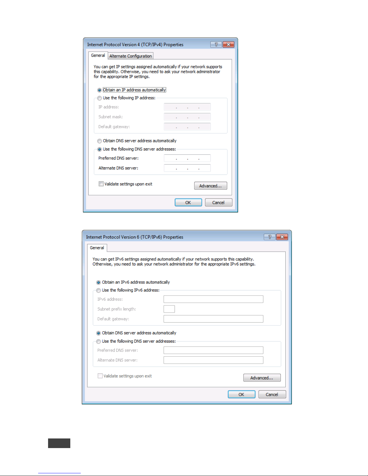
14 FC-6P - Connecting the FC-6P
Figure 8: Internet Protocol Version 4 Properties Window
Figure 9: Internet Protocol Version 6 Properties Window
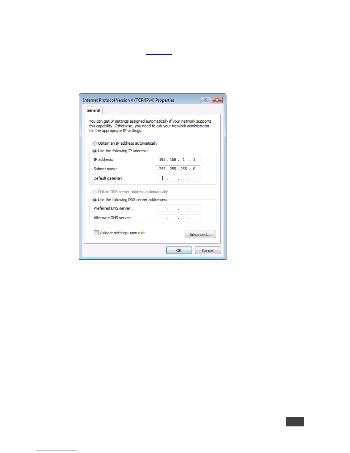
FC-6P – Connecting the FC-6P 15
5. Select Use the following IP Address for static IP addressing and fill in the
details as shown in Figure 10
.
For TCP/IPv4 you can use any IP address in the range 192.168.1.1 to
192.168.1.255 (excluding 192.168.1.39) that is provided by your IT
department.
Figure 10: Internet Protocol Properties Window
6. Click OK.
7. Click Close.
6.1.2 Connecting the Ethernet Port via a Network Hub or Switch
You can connect the Ethernet port of the FC-6P to the Ethernet port on a network
hub or switch using a straight-through cable with RJ-45 connectors.

16 FC-6P - Connecting the FC-6P
6.1.3 Connecting to the FC-6P via RS-232 or IR
To connect to the FC-6P via RS-232:
• Connect the RS-232, 3-pin, terminal block connectors on the rear panel of the
FC-6P using 3-wire cable (pin TX to pin 2, RX to pin 3, and G to pin 5) to the
RS-232 9-pin D-sub port on the devices to be controlled
To connect to the FC-6P via IR:
• Connect an IR blaster to one of the IR Outputs and place it within 4m to 8m (13
to 26ft) and in line-of-sight of the device to be controlled
—OR—
• Connect an IR emitter cable to one of the IR outputs and stick the emitter to the
IR sensor on the device to be controlled

FC-6P – Remote Operation via the Web UI 17
7 Remote Operation via the Web UI
The embedded Web UI can be used to remotely operate the FC-6P using a Web
browser and an Ethernet connection.
Before attempting to connect:
• Perform the initial configuration in Section 5.1
and connecting via Ethernet in
Section 6.1
• Ensure that your browser is supported (see Section 8)
7.1 Browsing the Web UI
To browse the Web UI pages:
1. Open your Internet browser. Type the IP address of the device (see
Section 5.1
) in the Address bar of your browser.
The Loading page appears followed shortly by the General Info page shown in
Figure 11
.
The General Info page displays the following:
• Model Name
• Firmware version
• Device serial number
• Web UI version
 Loading...